Unit - 4
Definition of Network Function
Q1) For network below 1, pole - zero pattern is represented in fig 1, find numerical value of R, L and c for z (0) =1?

Fig 1 Pole zero plot
A1)
Calculating z(s) by taking L.T of fig 1)
z(s) = (R+SL)*1/CS
(R+SL)+1/CS = R+SL / SRC+S2LC+1
Z(S)= S+R/L / C [S2+R/L S+1/LC]
Given z(0)=1
z(0)=R/L / C/LC =1
Z(0)=R=1
.: R=1
Polls are given as
S2+RS/L+1/LC=0
S=-R/2L +J
Zeros are given as
S+R / L=0
From pole zero plot value of pole location is at -1 so
-R / L = -1
-1/ L=-1
L=1H
Also imaginary part of pole from plot is
 =
=
1/LC-(R/2L)2 =11/4
1/C-(1/2)2=11/4
1/C-1/4=11/4
1/C=11/4+1/4
1/C=12/4 =3
C=1/3 F
Hence, value of R=1 L=14 and c=1/3 f
Q2) FOR the following circuit, FIND G12(S) =v2/v1
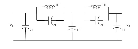
A2) Taking Laplace transform of above we have
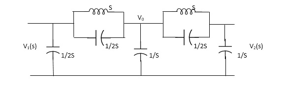
Fig 2 Laplace Transform of above circuit
Applying KCL at node v0
V0-V1(S) / S*1/2S/(S+1/2S) +V0+V2(S)/ (S*1/2S)/(S+1/2S)+V0/1/S=0
For Porr 2, We have,
v2-v0/(s*1/2s)/(s+1/2s)+v2/1/s =0 ---------(ii)
(v2-v0)(2s2+1) / s +sv2=0
v2 [2s2+1/s+s] = v0( 2s2+1)/ s
v0=v2(3s2+1) / (2s2+1)-----------(iii)
From (i) we have,
(v0-v1) /s (2s2+1) *sv0+(v0-v2)/5 (s2+1) =0
(2s2+1/5)v0-(2s2+1)/sv1+sv0+(2s2+1)/sv0-(s2+1)/s v2=0
(2s2+1)v1=(5s2+2)v0-(2s2+1)v2
Substitute value v0 from (iii) above
(2s2+1)v1 =[( 5s2+2)(3s2+1) /(2s2+1)-(2s2+1)]v2
(2s2+1)v1=(15s4+5s2+6s2+2-4s4+4s2) / (2s2+1 *v2
G12(s) = v2/v1 = (2s2+1) 2/11s4+15s2+1
Q3) Find the transfer function admittance ratio Y12(s) = I2(S) / V1(S)?

A3) Taking Laplace transform of above figure

Fig 3 Laplace Transform of above circuit
Applying KCL we get,
(V2-V1) / (3*1/2S) / (3+1/2S) * V2/ 1/2S+ V2/1/6 =0
(Y2-V1)(6S+1) / (6S+4) * (2S+6)V2V=0
BUT I2=-6V2
V2=-I2/6
We have ,
(6s+1) / (6s+4)*v2-(6s+1) / (6s+4)*v1 +(2s+6)v2=0
-[6s+1 / 6s+s+2s+6]I2 / 6 =V1(6S+1) / 6S+4
-[6S+1(2S+6)(6S+4)]I2= 6(6S+1)V1
-[(6S+1)*12S2+36S+8S+24] I2=6(6S+1)
I2 / V1 =-6(6S+1) / 12S2+50S+25
Y12(S) = I2(S) / V1(S) = -6(6S+1) / 12S2+50S+25
Q4) Find whether the following network function represent the driving point function.
a) f(s)= (s+1)/(s2+1) b) f(s) = 3s2+2s+1/ss3+9s2+3s+2 c) f(s)=(s2+1)2/s2(s+3)
A4)
a) f(s)=s+1/s2+1
It represents the driving point function:
b) F(S)= 3S2+2S+1 / 5S3+9S2+3S+2
It represents the driving point function.
b)F(s)=3s2+2s+1/5s3+9s2+3s+2
It represents the driving point function
c) f(s) = (s2+1)2/s2(5+3)
It has representative zeros, hence not valid
( s2+1)2=0
s2=+-1
s2=+-j,+-j
Q5) For the network shown, find driving point input impedance .plot the pole zero pattern for each as well.

Fig 4 (1) Circuit Diagram Fig 4(2) Circuit Diagram
A5) For Fig 4(1) taking L.T we have

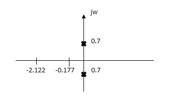
Fig 5 Laplace for Fig 4(1) with roots
Z11= 1+ 1 /S/3+1/25+1/1/4S
=1+ 1/ 5/3+1/6S
=1+ 18S/6S2+3
Z11=6S2+3+18S/ 6S2+3 =2S2+6S+2/2S2+1
Zeros of equations are taking lt.of circuit b)
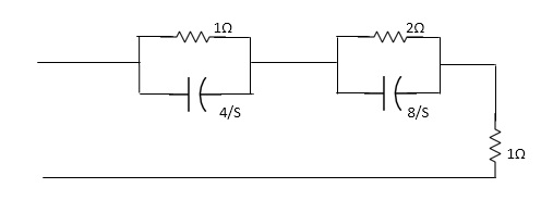
Fig 6 Laplace for Fig 4(2)
Z11= 1*4/5
1+4/5+2.8/3/2+8/5+1
=4/5+4 + 16/ 25+8+1
= 4/5+4+8/5+4+1
=s+12+4/(5+4)
Z11= S+16/(S+4)
For zeros of system
s+16=0
s=-16
For poles of system
s+4=0
s=-4
Q6) The Z21 – parameter for network shown is
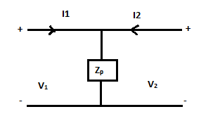
A6)
The z- parameter is given as
v1 = Z11I1 + Z12I2
v2 = Z11I1 + Z22I2
So, applying KVL we get
v1=Zp(I1+I2) = ZpI1+ZpI2
v2= Zp(I2+I1) = ZpI1+ZpI2
Comparing with above equation we get
Z11= Z12= Z21= Z22=Zp
Q7) The h22 – parameter for network shown is
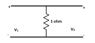
A7)
The h-parameter is given as
V1 = h11I1 + h12V2 (1)
I2 = h21I1 + h22V2 (2)
V1=R(I1+I2) (3)
V2=R(I1+I2) (4)
From (4) finding I2
 =I2
=I2
V1=RI1+R[ -I1]
-I1]
V1=RI1+V2-RI1
V1=V2 (5)
Comparing (1) and (5)
h11=0
h12=1
From (2)
I2=
I2=-I1+ (6)
(6)
Comparing (6) and (2)
h21=-1
h22=
Q8) For the network below calculate y11&y22
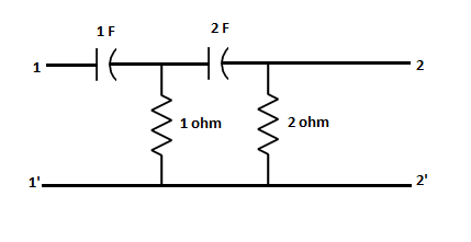
A8)
Taking Laplace Transform of above circuit we get
For port 1
I1=s(V1-V3) (1)
For node V3
S(V3-V1)+V3+(V3-V2)2s=0
V3= +
+ 
 (2)
(2)
Substituting V3 from (2) in (1)
SV1-s[ +
+ 
 ]=I1
]=I1
 V1-
V1- V2=I1 (3)
From (3) and (1)
y11=
For port 2
 +(V2-V3)2s=I2 (4)
Substituting V3 From (2) in (4) and solving we get
y22=
Q9) The y22,y11- parameter of the network are
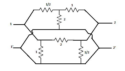
A9)
Converting the upper part T-network to  network we get
y11a= =
= mho
mho
y12a=- mho
mho
y21a=- mho
mho
y22a= =
=  mho
mho
For the lower circuit from the question we can directly write
y11b=1 mho
mho
y12b= mho
mho
y21b=- mho
mho
y22b=2+ =
=  mho
mho
The overall y-parameter of the circuit is given as
y11=y11a+y11b= +
+ =
= mho
mho
y12=y12a+y12b=
 =-=
=-= mho
mho
y21=y21a+y21b=- -
- =
=  mho
mho
y22=y22a+y22b= =
=  mho
mho
Q10) With the usual notation, a two-port series resistive network satisfies
A = D=  . The Z11 at the network is?
A10)
The ABCD parameters are given as
V1 = AV2 - BI2 (1)
I1 = CV2 - DI2 (2)
The z- parameter is given as
v1 = Z11I1 + Z12I2 (3)
v2 = Z11I1 + Z22I2 (4)
Converting equation (1) in the form of (3). We substitute value of V2 from (2) in (1)
V2= +
+ (5)
(5)
Substituting V2 from (5) in (1) we get
V1=A[ +
+ – BI2
– BI2
V1= +
+ - BI2 (6)
But we know A=
From (1) and (6)
Z11= =4/3
=4/3
Q11) For given circuit calculate h21
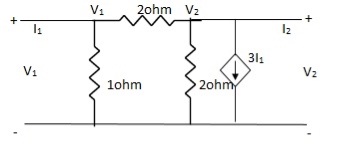
A11)
 +
+  = I1 (1)
 V1 -
V1 -  = I1
= I1
 V1 =
V1 =  + I1
+ I1
V1 = +
+  I1
I1
-  + 3I1 = I2
3I1 + V2 = I2
= I2
From (1)
I2 = 3I1 + V2 –  [
[ I1 +
I1 +  V2]
V2]
I2 =  I1 +
I1 +  V2
V2
h11 = 
h12 = 
h21 = 
h22 = 
Q12) The value of forward current gain Y21 from below is
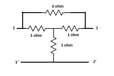
A12)
Converting the T network to  network we get
The y-parameter is given as
I1 = Y11V1 + Y12V2
I2 = Y21V1 + Y22V2
From port 2
 +
+ (V2-V1)=I2
Comparing with standard equation we get
y21=-3/5 mho
Q13) For the following network find which represents driving point function


A13)

It has no repeated zeros. Hence, not valid

No repeated zeros. Hence valid.
Q14) In a passive two port network, the open line impedance matrix is  If the input port is interchanged with O/P port, then open circuit Impedance matrix will be?
A14)
If the ports are inter changed than we will get the inverse matrix for the above given matrix 
Q15) Find Z parameter, is the network reciprocal?
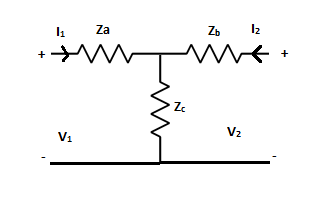
A15)
The z- parameter is given as
v1 = Z11I1 + Z12I2
v2 = Z11I1 + Z22I2
V1=ZaI1+Zc(I1+I2)=(Za+Zc)I1+ZcI2
V2=ZcI1+(Zb+Zc)I2
Comparing above equations we get
Z11=Za+Zc
Z12=Zc
Z21=Zc
Z22=Zb+Zc
As Z12=Zc=Z21
Hence, its reciprocal network
Q16) Find Y21
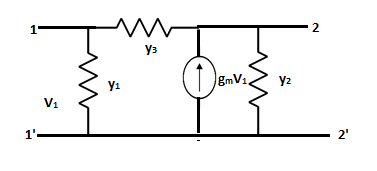
A16)
The y-parameters are given as
I1 = Y11V1 + Y12V2
I2 = Y21V1 + Y22V2
Writing node equation for V2
I2=y2V2+y3(V2-V1)-gmV1
I2=(-y3-gm)V1+(y2+y3)V2
Comparing the above equations
Y21= -y3-gm
Q17) Find y parameters
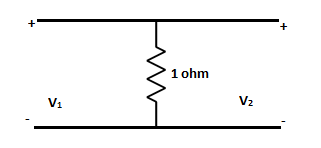
A17)
The y-parameter is given as
I1 = Y11V1 + Y12V2
I2 = Y21V1 + Y22V2
Here Y parameter does not exist as V1=V2
Q18) With help of waveform explain all the standard test signals?
A18) The Impulse signal, Ramp signal, unit step and parabolic signals are used as the standard test signals. All these signals are explained below.
Impulse Signal: -
This signal has zero amplitude everywhere except at the origin. Fig below shown the representation of Impulse signal.
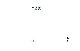
Fig: Unit Impulse Signal
The mathematical representations
A (t) = 0 for t ≠0
 dt = A e
Where A represent energy or area of the Laplace Transform of Impulse signal is
L [A (t)] = A
UNIT IMPULSE SIGNAL:
If A = 1
 (t) = 0 for t ≠0
L [ (t)] = 1
The transfer function of a linear time invariant
System is the Laplace transform of the impulse response of the system. If a unit impulse signal is applied to system then Laplace transform of the output c(s) is the transfer function G(s)
As we know G(s) = c(s)/R(S)
r(t) =  (t)
(t)
R(s) = L [ (t)] = 1
:. G(S) = C(s)
Step signal: -
Step signal of size A is a signal that change from zero level to A in zero time and stays there forever.
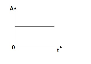
Fig: Unit Step Signal
r(t)= A t >=0
=0 t<0
L[r(t)] = R(s) = A/s
UNIT STEP SIGNAL: - If the magnitude of the slip signal is I then it is called unit step signal.
u(t) = 1
t>=0
t<0
L[u(t)] = 1/s
Ramp Signal:
The vamp signal increase linearly with time from initial value of zero at t= 0 as shown in fig is below
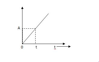
Fig: Ramp Signal
r(t) = At t>=0
=0 t<0
A is the slope of the line The Laplace transform of ramp signal is
L[r(t)] = R(s) = A/s2
Parabolic Signal:
The instantaneous value of a parabolic signal varies as square of the time from an initial value of zero t=0. The signal representation in fig 14 below.
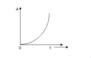
Fig: Parabolic Signal
r(t) At2 t>=0
=0 t<0
Then Laplace Transform is given as
R(s) = L[At2] = 2A/s3
If no error then E(t) =0, :. R(t) = c(t), output is tracking the input.
Steady state Errors signal (ess): - (t  )
)
Ess = t  e(t)
e(t)
Using final values, the theorem
 = ess =
  S.E (s)
ess=  S[R(s)/1+G/(s)]
Q19) The open loop transfer function of a system with unity feedback gain G( S ) = 20 / S2 + 5S + 4. Determine the ξ, wn
A19)
Finding closed loop transfer function,
C( S ) / R( S ) = G( S ) / 1 + G( S ) + H( S )
As it is unity feedback so, H(S) = 1
C(S)/R(S) = G(S)/1 + G(S)
= 20/S2 + 5S + 4/1 + 20/S2 + 5S + 4
C(S)/R(S) = 20/S2 + 5S + 24
Standard equation for second order system,
S2 + 2ξWnS + Wn2 = 0
We have,
S2 + 5S + 24 = 0
Wn2 = 24
Wn = 4.89 rad/sec
2ξWn = 5
(a). ξ = 5/2 x 4.89 = 0.511
Q20) Mention restrictions of pole zero on driving function?
A20)
Restrictions of poles and zeros on driving point function
N(s) =p(s) =qosn+q,sn--------an/ q(s) bosn+b,sn-----------bn
1) All coefficient of p(s) and q(s) should be real and positive
2) poles and zeros must be conjugal whether imaginary or complex
3) Real part of poles and zeros must be negative or zero.
4) The degree of p(s) may differ either by zero or 1.
5) Lowest degree of p(s) and q(s) may differ at the most by one.
6) p(s) and q(s) cannot missing terms between highest and lowest degree unless all when or all odd terms are missing.