Unit - 5
Three Phase Induction machine
Q1) With suitable diagram explain construction and working of permanent magnet dc motor.
A1)
Permanent magnet DC motor-
The basic working principle of DC motor is based on the fact that whenever a current-carrying conductor is placed inside a magnetic field there will be mechanical force experienced by that conductor.
In these motors, the magnetic field is established by means of a magnet. The magnet can be of any types i.e. it may be an electromagnet or it can be a permanent magnet.
Construction-
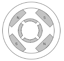
A PMDC motor mainly consists of two parts. A stator and an armature. Here the stator which is a steel cylinder. The magnets are mounted in the inner periphery of the cylinder. The permanent magnets are mounted in such a way that the N-pole and S-pole of each magnet are alternatively faced towards armature.
In addition to holding the magnet on its inner periphery, the Steel cylindrical stator also serves as a low reluctance return path for the magnetic flux.
Although field coils are not required in permanent magnet DC motor but still, it is sometimes found that they are used along with permanent magnet. This is because if permanent magnet loses their strength, these lost magnetic strengths can be compensated by field excitation through these field coils.
The rotor of the PMDC motor is similar to other DC motors.
Equivalent circuit:
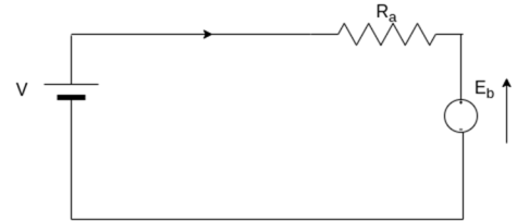
As in PMDC motor, the field is produced by a permanent magnet, there is no need for drawing field coils in the equivalent circuit of permanent magnet DC motor.

Advantages-
1) No need for field excitation arrangement.
2) No input power is consumed for excitation which improves the efficiency of DC motor.
3) No field coil hence space for field coil is saved which reduces the overall size of the motor.
4) Cheaper and economical for fractional KW rated applications.
Disadvantages-
1) In the case of armature reaction of DC motor cannot be compensated hence the magnetic strength of the field may get weak due to demagnetizing effect.
2) Due to excessive armature current, there is a chance of getting the poles permanently demagnetized (during starting, reversal, overloading condition)
3) The field in the air gap is fixed and limited and it cannot be controlled externally. Therefore very efficient speed control of DC motor in this type of motor is difficult.
Applications-
PMDC motor is extensively used where small DC motors are required and also very effective control is not required, such as in automobiles starter, toys, wipers, washers, hot blowers, air conditioners, computer disk drives and in many more.
Q2) Describe with neat diagram, construction and working of permanent magnet stepper motor.
A2)
Permanent magnet stepper motor
The stator of a permanent magnet stepper motor is similar to that of a single stack variable reluctance motor. Rotor is cylindrical and consists of radially magnetized permanent magnets.
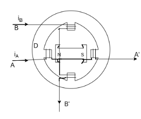
The above figure shows a two-pole permanent magnet stepper.
When phase A is excited with the direction of current  as shown, north pole of the rotor aligns with the phase A pole on the left. The router turns through 90° when excitation is switched from phase A to B. The direction of rotation depends on the direction of current in phase B. When
  a positive is the rotor turns clockwise and when negative it turns anticlockwise. Thus polarities of windings current determine the direction of rotation and for bidirectional operation provision has to be made for the supply of current in either direction.
Advantages
1) They are compatible with digital systems.
2) A wide range of step angles is available off-the-shelf from most manufacturers, in the range of 1.8 to 90°.
3) Bi-directional control is available.
4) Maximum torque occurs at low pulse rates. The stepper motor can, therefore, accelerate its load easily.
5) Low speeds are possible without A reduction gear.
6) The starting current is low.
Disadvantages
1) Efficiency is low.
2) Proper matching between the load, motor and its drive is required.
Q3) Explain Stator side speed control methods of three phase induction motor.
A3)
The speed control of induction motor from the stator side are further classified as,
1) Changing the number of stator poles.
2) Controlling supply voltage
3) V/f control or frequency control
4) Adding rheostat in the stator circuit
- Pole changing methods:
The number of stator poles can be changed by
a) Multiple stator windings- In this method, the stator is provided with two separate windings which are wound for two different pole numbers.
b) Method of consequent poles:-In this method a single static winding is divided into two coils groups. The terminals of all these groups are brought out. The number of poles can be changed with only simple changes in coil connections. The number of poles can be changed in the ratio of 2:1.
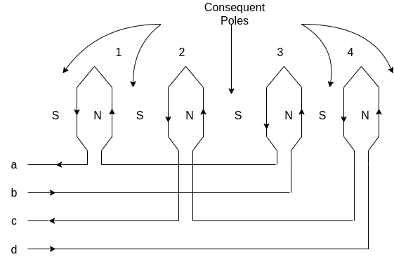
c) Pole amplitude modulation technique: This method of speed control by pole changing are suitable for cage motors only because the cage the rotor automatically develops a number of poles equal to the poles of the stator winding.
2. Controlling supply voltage:
The speed of a three-phase induction motor can be varied by varying the supply voltage.

Where 

Therefore the speed of the rotor at maximum torque is

The torque developed is proportional to the square of the supply voltage and the slip at maximum torque is independent of the supply voltage.
Variation of supply voltage does not alter the synchronous speed also.
Torque speed characteristics of a three-phase induction motor for varying supply voltage and a fan load is shown below.
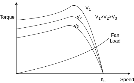
Speed control is obtained by varying the supply voltage until the torque required by the load is developed at the desired speed.
As the torque is proportional to the square of the supply voltage and current is proportional to the voltage. Therefore as a voltage is reduced to reduce speed for the same current the torque developed by the motor is reduced.
This method is suitable for applications where load torque decreases with speed, as in the case of a fan load.
The speed of the motor can be varied within a small range by this method.
Since the operation at voltage is higher than the rated voltage is not permissible, this method allows speed control only below the normal rated speed.
This method is suitable for fan or pump drives where the load torque varies as the square of the speed. These drives require low torque at low speeds and this can be obtained with low applied voltage without excessive motor current.
Q4) Explain V/F speed control method of three phase induction motor.
A4) V/F control or variable frequency control

The synchronous speed of an induction motor is given by 
The synchronous speed and therefore the speed of the motor can be controlled by varying the supply frequency.
The EMF induced in the stator of the induction motor is given by

Therefore, if the supply frequency is changed,  will also be changed to maintain the same air gap flux. If the stator voltage drop is neglected the terminal voltage
  is equal to
  To avoid saturation and to minimize losses, the motor is operated at rated air gap flux by varying terminal voltage with frequency to maintain ratio constant at the rated value. This type of control is known as constant voltage per hertz.
The variable-frequency supply is generally obtained by the following converters
1) Voltage source inverter
2) Current source inverter
3) Cycloconverter
Inverter converts of fixed voltage DC to a fixed voltage AC with variable frequency.
A cycloconverter converts a fixed voltage and fixed frequency AC to a variable voltage and variable frequency AC.
Cycloconverter controlled induction motor drive is suitable only for large power drives and to get low speeds.
Q5) Draw complete slip-torque characteristics of three phase induction motor and explain working of induction generator.
A5)
An induction machine is sometimes used as a generator.
The following figure shows the complete torque-speed characteristic of a three-phase induction machine for all ranges of speed.
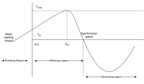
Initially, the induction machine is started as a motor. It draws lagging reactive volt-ampere from the main supply.
Then the speed of the machine is increased above the synchronous speed by an external prime mover in the same direction as the rotating field produced by the stator windings.
Then the induction machine will operate as an induction generator and will produce generating torque. This generating torque is opposite to the rotation of the rotor. Under these circumstances the slip is negative and the induction generator delivers electrical energy to the supply mains.
The output of the induction generator depends upon the magnitude of the negative slip or on how fast the above synchronous speed the rotor is driven in the same direction.
In generating mode, there is a maximum possible induced torque called push over-torque of the generator. If the prime mover applies a torque greater than the pushover torque, The generator will over speed.
The rotating magnetic field in the polyphase induction motor is produced due to the exciting current supplied to the stator winding from the supply line. The supply must continue to be available even if the machine-driven above synchronous speed. In other words an induction generator is not self-excited generator.
In induction generators, the reactive power required to establish the air gap magnetic flux is provided by a capacitor Bank connected to the machine in case of a stand-alone system.
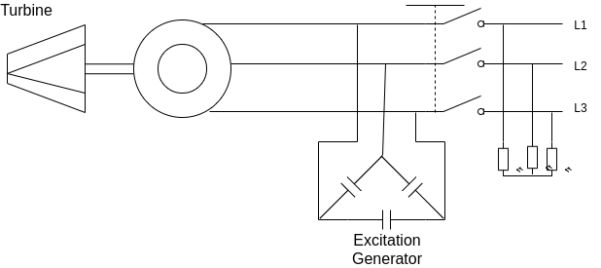
The motor runs slightly above the synchronous speed at no load by a prime mover.
A small EMF is induced in the stator at a frequency proportional to the rotor speed.
This voltage appears across the three-phase capacitor bank giving rise to a leading current drawn by the capacitor Bank. This is equivalent to the leading current supplied back to the generator.
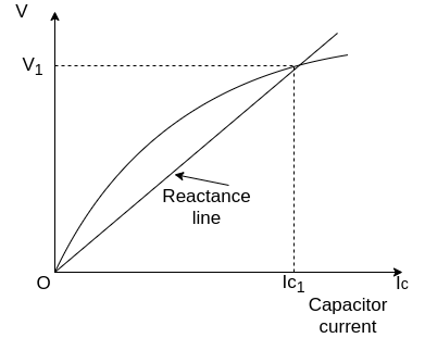
The flux set up by this current assists current the initial residue flux causing an increase in the net flux, which in turn causes a net increase in voltage. This increase in voltage causes a further increase in exciting current causing a further increase in the terminal voltage.
This voltage builds up to a point where the magnetization characteristic of the machine and the voltage-current characteristic of the capacitor Bank intersects each other.
At this point, the reactive volt-ampere demanded by the generator is equal to the reactive volt-ampere supplied by the capacitor bank.
The operating frequency is affected by the load and it depends upon the rotor speed.
For lagging power factor load the voltage collapses very rapidly.
Q6) Explain the construction and working of Brushless dc Motor.
A6)
Brushless DC motor
The cross-section of a three-phase 2 pole trapezoidal PMAC motor is shown. It has permanent magnet rotor with wide pole arc. The stator has three concentrated phase windings, which are displaced by 120° and each phase winding span 60° on each side.
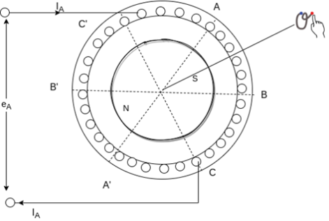
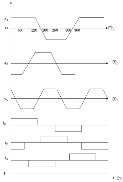
When a revolving in the counter clockwise direction, up to 120° rotation, all top conductors of phase A will be linking the South Pole, and all bottom conductors of phase A will be linking the north pole.
Hence the voltage induced in phase A will be the same during 120° rotation. Beyond 120° rotation, some conductors in the top link north pole and others the South Pole. The same happens with the bottom conductors.
Hence, the voltage induced in phase linearly reverses in the next 60° rotation. Thus an inverter fed trapezoidal PMAC motor drive operating in self-controlled made is called DC motor.
A brushless DC motor employing a voltage source converter and a trapezoidal PMAC motor is shown below
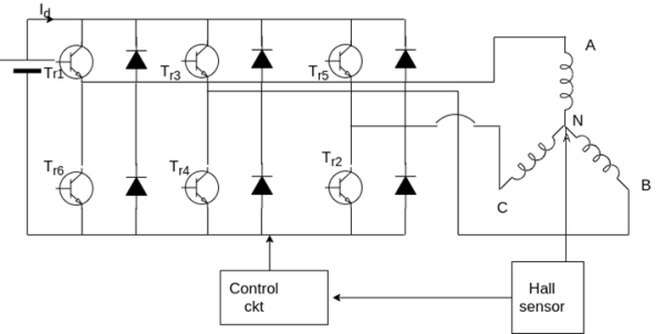


During each 60° interval, current enters one phase and comes out of another phase, therefore power supplied to the motor in each such interval is,


Thus torque is proportional to current  . It can be shown that a DC current
  flows in the DC link.
Regenerative braking operation is obtained by reversing phase currents.
Like a DC motor, inverter fed trapezoidal PMAC motor has a voltage induced proportional to speed, torque is proportional to armature current, and stator and the rotor fields remain stationary with respect to each other.
However, it does not have brushes and associated disadvantages, hence this motor is commonly known as brushless DC motor. This motor is also conceived as electronically commutated DC motor because the inverter here performs the same function as the brushes and commutator in a DC motor i.e. Shift currents between armature conductors to keep the stator and the rotor fields stationary with respect to each other.
Advantages
No maintenance, have a long life, high reliability, low inertia and friction, and low radio frequency interference and noise.
Applications
Turn table drives in record players, tape drive for video recorders, spindle drives for hard disk drives for computers, low cost and low power drive in computer peripherals instruments and control systems.
In aerospace, biomedical like cryogenic coolers and artificial heat pumps.
Q7) Explain the construction and working of Variable reluctance stepper Motor.
A7)
Variable reluctance type stepper motor
The principle of operation of a variable reluctance stepper motor is based on the property of flux lines to occupy a low reluctance path. The stator and rotor, therefore get aligned such that the magnetic reluctance is minimum. A variable reluctance stepper motor can be of single stack type or the multi-stack type.
Single stack type-
This motor has a salient pole stator. The stator has concentrated windings placed over the stator poles.
The rotor is a slotted structure made from a ferromagnetic material and carries no winding.
Both the stator and the rotor are made up of high-quality magnetic materials having very high permeability so that the exciting current required is very small.

When the stator phases are excited in a proper sequence from DC source with the help of semiconductors switches a magnetic field is produced.
The ferromagnetic rotor occupies the position which presents minimum reluctance to the stator fields.
That is the rotor axis aligns itself to the stator field axis.
Working-: When winding A is energized, the rotor aligns with the axis of phase A. The rotor is stable in this position and cannot move until phase A is de-energized.
Next phase B is excited and A is disconnected. The rotor moves through 90° in a clockwise direction to align with the resultant air-gap field which now lies along the axis of phase B.
The magnitude of step angle for any PM or VR stepper motor is given by

Where 
 number of stator phases or stack
 =number of the rotor teeth
Or 
Where.  = stator poles
The step angle can be reduced from 90° to 45° by exciting phases in the sequence A, A+B , B , B+C , C, C+D , D, D+A, A
A lower number of step angles can be obtained by using a stepping motor with more number of poles on stator and teeth on rotor.
Q8) Explain different methods of controlling of three phase induction motor.
A8)
Speed control of induction motor
The rotor speed of an induction motor is given by

And


From the above equation, It is seen that the motor speed can be changed by a change in frequency f, number of poles P and slips.
The torque produced by a three-phase induction motor is given by

When a the rotor is at standstill slip S is 1, so the equation of torque is

Where,
 is the rotor EMF
 is the synchronous speed
 is the rotor resistance
 is the rotor inductive reactance
The speed of induction motor is changed from both stator and the rotor side.
The speed control of induction motor from the stator side are further classified as,
- Changing the number of stator poles.
- Controlling supply voltage
- V/f control or frequency control
- Adding rheostat in the stator circuit
The speed control of 3 phase induction motor from the rotor side are further classified as
1) Adding external resistance on the rotor side
2) Cascade control method
3) Injecting slip frequency EMF into the rotor side.
Q9) A 10 hp, 1760 rpm, 440V, three-phase induction motor operates as an asynchronous generator. The full load current of the motor is 10 A and the full load power factor is 0.8. Determine the required capacitors per phase if capacitors are connected in delta.
A9)
Apparent power


Active power


Reactive power


For a machine to run as an asynchronous generator, capacitor bank must supply a minimum  VAR per phase
Capacitive current 

Capacitive reactance per phase 
Minimum capacitance per phase


If the load also absorbs reactive power, the capacitor bank must be increased in size to compensate.
Prime mover speed should be used to generate a frequency of 50 Hertz.
Q10) Compare of a standard motor and energy-efficient motor
A10)
Parameters | Standard motor | Energy-efficient motor |
Stator and the Rotor material | Low carbon laminated Silicon Steel. | High-grade Silicon Steel. |
Loss in core | More about 6.6 watts/Kg | Low, 3.3 watts/Kg |
Laminations | Thicker lamination increases Eddy current losses | Very thin lamination decreases Eddy current losses. |
Insulation between lamination | Moderate | Insulation improved |
Length of core | Standard length (less) | Longer core length |
Operation noise | More noisy operation | Less noisy operation |
Stray losses | More stray losses | Very less, stray losses |
Air gap | Moderate | Narrow air gap decreases the magnetizing current |
Losses and P.F. | More losses decrease P.F. | Fewer losses better P.F. |
Overload capacity | Lesser capacity | More capacity |
Q11) Explain the Torque vs stepping rate characteristics
A11)
Torque vs stepping rate characteristics-
As the stepping rate increased, the rotor has less time available to drive the load from one position to the next. Beyond a certain pulsing rate, the router cannot follow the command and begins to miss pulses.

If the values of load torque and pulsing rate are such that the point of operation lies to the left of the curve I, then the motor can start and also synchronize without missing a pulse if the stepping rate less than 
Once the motor has started and synchronized, the stepping rate can be increased for the same load torque without missing a step. For load torque  after starting and synchronization, the stepping rate can be increased up to
  without missing a step or without losing synchronism.
However, if the stepping rate is increased beyond  then the motor will lose synchronism.
Q12) The stator of a 3-phase induction motor has 5 slots per pole per phase. If supply frequency is 50Hz. Calculate
a) number of stator poles produced and total number of slots in stator.
b) Speed of rotating stator flux.?
A12) a) P=2n=2*5=10 poles
Total number of slots= 5 slots/pole/phase * 10 poles * 3 phase=150
a) Ns= =120x50/10=600rpm
Q13) A 3-phase induction motor is wound for 5 poles and is supplied from 50 Hz. Calculate
a) synchronous speed
b) rotor speed when slip is 4%
c) rotor frequency when rotor runs at 500 rpm?
A13) a) Ns= =120x50/5=1200 rpm
b) rotor speed N=Ns(1-s)=1200(1-0.04)=1152 rpm
c)when rotor speed is 500 rpm, slip s=(Ns-N)/Ns=(1200-500)/1200=0.58
Rotor current frequency f’=sf=0.58x50=29.17 Hz
Q14) A 3-phase, 50 Hz,3-pole induction motor has a slip of 4%. Calculate a)speed of rotor. B) frequency of rotor emf. If the rotor as a resistance of 2ohm, and standstill reactance of 4ohm, calculate the power factor c) at standstill and d) at a speed of 1200rpm?
A14) Ns= =120x50/3=2000 rpm
a) Speed of rotor N=Ns(1-s)=2000(1-0.04)=1920 rpm
b) Frequency or rotor = f’=sf=0.04x50=2Hz
R2=2ohm, X2=4ohm
Z2=R2+jX2=2+j4=4.47 63.43o ohm
c)Power factor cosφ2=0.44(lag)
Slip at speed 1200rpm s= 2000-1200/2000=0.4
Rotor impedance at slip s=0.4 is
Z2s=R2+jsX2=2+jx0.4x4=2.56 oohm
oohm
Power factor at 1200rpm is cos φ2s=cos38.66o=0.78(lag)
Q15) A 3-phase induction motor star connected rotor has an induced emf of 70volts between slip rings at standstill on open circuit. The rotor has a resistance and reactance per phase of 1ohm and 5ohm respectively. Calculate current/phase and power factor when slip rings are short circuited?
A15) Standstill emf/rotor phase=70/
Rotor impedance/phase= ohm
ohm
Rotor current/phase=40.4/5.09=7.92A
Power factor cosφ=0.99
Q16) A 3-phase induction motor star connected rotor has an induced emf of 70volts between slip rings at standstill on open circuit. The rotor has a resistance and reactance per phase of 1ohm and 5ohm respectively. Calculate current/phase and power factor when slip rings are connected to star connected rheostat of 2ohm?
A16) Rotor resistance/phase=2+1=3 ohm
Rotor impedance/phase= =5.83 ohm
Rotor current/phase= (70/ )/5.83=6.93A
Cosφ=3/5.83=0.514
Q17) A 6-pole, 3-phase induction motor operates from a supply whose frequency is 50Hz. Calculate i) speed at which the magnetic field of stator is rotating. Ii)speed of rotor when slip is 4%. Iii)frequency of rotor current when slip is 3%?
A17) i) Stator revolves at synchronous speed. So, Ns=120f/P=120 x 50/6=1000rpm
Ii)rotor speed N=(1-s) Ns= (1-0.04) x 1000=960rpm
Iii)frequency of rotor current f’=sf=0.03 x 50=90rpm
Q18) A 12-pole, 3-phase, 600V, 50Hz, star connected induction motor has rotor-resistance and standstill reactance of 0.04 and 0.6 ohm per phase respectively. Calculate i) speed of max. Torque ii) ratio of full load torque to max torque, if full load speed is 495rpm?
A18) Ns=120f/P=120 x 50/12=500 rpm
For r=0.04 and x=0.6 ohm, slip torque is
Smt=a=r/x=0.04/0.6=0.067
i)Speed =(1-Smt)N=(1-0.067) x 500=466.67 rpm
Ii) Full load speed = 495rpm, slip=0.01,at full-load
 =
= =
= =0.29
=0.29
Q19) A 3-phase 400/200V, Y-Y connected wound rotor induction motor has 0.05 ohm resistance and 0.2 ohm stand still reactance per phase. Find the additional resistance required in the rotor circuit to make starting torque equal to the maximum torque of motor?
A19)

Given Tst=Tmax
1= , a=1
, a=1
a=
1=
r=0.15 Ω
Q20) A 50hz ,6-pole induction motor has full load slip of 4%. The rotor resistance/phase = 0.02ohm and standstill reactance/phase=0.1 ohm. Find the ratio of maximum to full load torque and the speed at which the maximum torque occurs?
A20)

a=R2/X2=0.02/0.1=0.02
 = 0.8
= 0.8
Ns=120 x 50/6=1000rpm,
sm=a(for maximum torque)=0.02
N= (1-0.02) x 1000=980rpm