Unit - 5
Two Port Networks
Q1) For the network shown below 1) show that with port 2) open the driving point input impedance 1π) b) find the voltage, ratio transfer function 1/2 for the two port network.
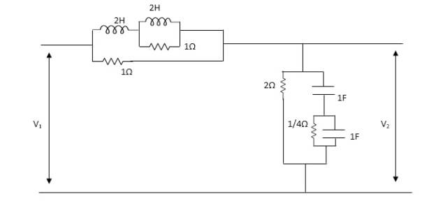
A1) From above network we take L.T
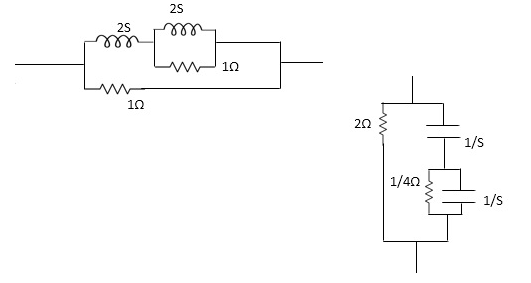
Fig 1 Laplace Transform for above circuit
Reducing we get,
Z1=(25+25*1 / 25+1)*1
25+25*1 / 25+1*1
Z1=4S2+45/452+65+1
Z2=(1/4S/1/4+1/5+1/5)*2=1/45/1/4+1/3+1/5+2
=2(5+5+4) / 5+5+4+25(5+4) = 2(25+4)/252+10S+4
Z2=25+4/252+10+4
Applying KVL, in the circuit
V1=I1Z1+I,Z2 -----------1
V2= I1Z2 ...............2
.: V1=I1Z1+V
V1 / I1= (Z1+Z2) (from----1)
Dividing equation 2 by 1
G12=Z 2 / Z1+Z2
Calculating z11 we have,
Z11=Z1+Z2
Z11 = 4S2+4S / 4S2+6S+1 * 2S+4/S2+SS+2
=(4S2+4S)(S2+SS+2)+(2S+4)(4S2+6S+1) / (4S2+6S+1)(S2+SS+2)
Z11=4S4+20S3+8S2+4S3+20S2+8S+8S3+12S2+25+16S2+4 /(4S2+6S+1)(S2+SS+2)
= (4S4+32S3+5652+345+4 / (4S2+6S+1)(S2+SS+2)
G12= Z2 / Z1+Z2
= (2S+4) / (S2+SS+2) / (4S+32S3+56S2+34S+4) / (4S2+6S+1)(S2+SS+)
G12= (2S+4)(4S2+6S+1) / 4S4+32S3+56S2+34S+4
Q2) For the network shown, find driving point input impedance. Plot the pole zero pattern for each as well.

Fig 2 (1) Circuit Diagram Fig 2(2) Circuit Diagram
A2) From Fig 2(1) taking L.T we have
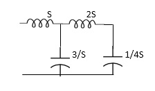
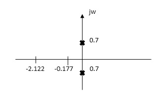
Fig 3 Laplace for Fig 2(1) with roots
Z11= 1+ 1 /S/3+1/25+1/1/4S
=1+ 1/ 5/3+1/6S
=1+ 18S/6S2+3
Z11=6S2+3+18S/ 6S2+3 =2S2+6S+2/2S2+1
Zeros of equations are taking lt.of circuit b)
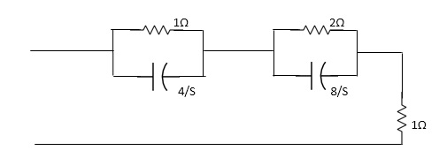
Fig 4 Laplace for Fig 2(2)
Z11= 1*4/5
=1+4/5+2.8/3/2+8/5+1
=4/5+4 + 16/ 25+8+1
= 4/5+4+8/5+4+1
=s+12+4/(5+4)
Z11= S+16/(S+4)
For zeros of system
s+16=0
s=-16
For poles of system
s+4=0
s=-4
Q3) Find Z-parameter
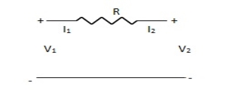
A3) I1 = -I2
Current dependent so Z-parameter doesn’t exist
Q4) Find z-parameter
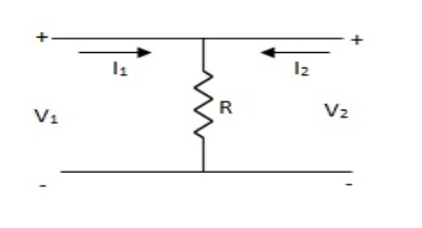
A4) V1 =R (I1 + I2)
V2 = R (I1 + I2)
Z11 = Z12 = Z21 = Z22 = R
Q5) Find z-parameter?
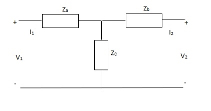
A5) V1 = I1Za + I1Zc + I2Zc
= (Za + Zc)I1 + ZcI2
V2 = I2Zb + I2Zc + I1Zc
= (Zb + Zc)I1 + ZcI1
Z11 = (Za + Zc)
Z12 = Zc = Z21
Z22 = (Zb + Zc)
Q6) Find z-parameter?
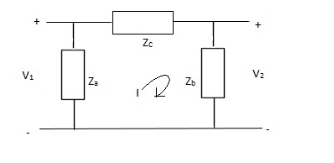
A6) V1 = Za(I1 - I)
(I - I1)Za+ IZc+ Zb(I + I2) = 0
I(Za + Zb + Zc) – I1Za + I2Zb = 0
I = 
V1 = ZaI1 - Za
=  I1 + I2
V2 = Zb(I2 + I)
= ZbI2 + Zb
=  I2 + I2
Z11 = 
Z12 = Z21 = 
Z22 = 
Q7) Find z parameter using conversion?
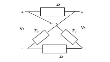
A7)
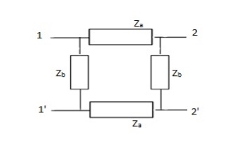
Z11 =  I2=0
I2=0
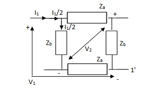
V1 -  (Za + Zb) = 0
 = Z11 =
Z21 =  I2=0
I2=0
V2 -  Zb +
Zb + Za = 0
 =
= 
Z12 = 
Z22 = 
Q8) Find Z21?
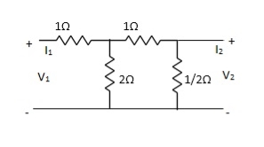
A8) Z21 =  I2=0
I2=0
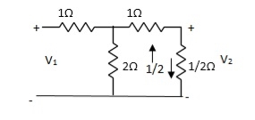
I1/2 = 
=  I1
I1
V2 =  I1/2
I1/2
=  ×
×  I1
I1
=  I1
I1
Z21 =  I2 = 0 =
  I1 Ω
I1 Ω
Q9) Find overall Y-parameter?
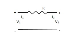
A9) V1 – I1R – V2 = 0
V1 – V2 = I1R
I1 =  V1 -
V1 -  V2
V2
V2 = I2R + V1
I2 = -  V1 +
V1 +  V2
V2
Y11 = 
Y12 = Y21 = 
Y22 = 
The over all Y parameter is given as

Q10) Find overall Y-parameter
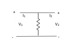
A10) Y-parameter does not exist as V1 = V2
Q11) Find overall Y-parameter?
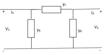
A11) I1 = V1Ya + (V1 – V2)Yc
I1 = (Ya + Yc)V1 - YcV2
I2 = V2Yb + (V2 – V1)Yc
I1 = (Yb + Yc)V2 - YcV1
Y11 = Yb + Yc
Y12 = Y21 = - Yc
Y22 = Yb + Yc
Q12) Find overall Y-parameter?
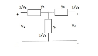
A12)
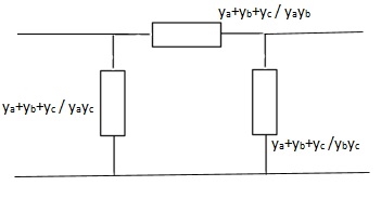
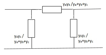
The overall y parameter is given by

Q13) Find all the Transmission parameters?
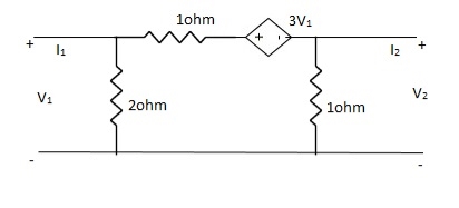
A13)
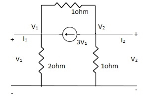
-3V1 – I1 +  +
+  = 0
= 0
 +
+  = I1
= I1
 V1 – V2 = I1
 V1 = V2 + I1
V1= V2-
V2-  I1----------------(1)
I2 = 3V1 + V2 + V2 – V1
I2 = 2V1 + 2V2
2V1 = I2 - 2V2
2V1 = - 2V2 + I2
V1 = -V2 +  I2 ----------------(2)
A = -1
B = 
From (1) & (2)
-V2 +  I2 =
I2 =  I1 -
I1 -  V2
V2
 V2 - V2 +
  I2 =
I2 =  I1
I1
 I1 =
I1 =  V2 + V2 -
  I2
I2
I1 =  V2 -
V2 -  I2
I2
C = 
D = 
Q14) Find all the Transmission parameters?
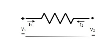
A14) V1 = RI1 + V2 ----------------(1)
I2R = V2 – V1
I2 =  V2 -
V2 -  V1
V1
I2R = V2 – V1
V1 = I2R - V2 --------------------(2)
A = 1
B = R
From (2) in (1)
V2 - I2R = V2 + RI1
I2 = -I1
C = 0
D = 1
Q15) Find all the Transmission parameters?
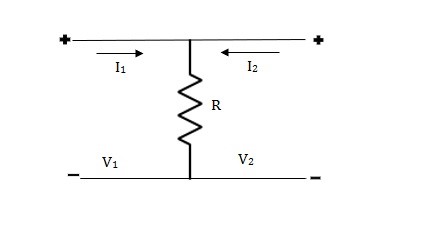
A15) V1 = R(I1 + I2)
V2 = R(I1 + I2)
V1 = V2 + 0I2
A = 1
B = 0
V2 = RI1 + RI2
RI1= V2 - RI2
I1 =  V2 – I2
C =  , D = 1
Q16) Find all h-parameter?
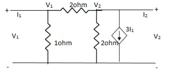
A16)
 +
+  = I1
= I1
 V1 -
V1 -  = I1
= I1
 V1 =
V1 =  + I1
+ I1
V1 = +
+  I1
I1
-  + 3I1 = I2
3I1 + V2 = I2
= I2
From (1)
I2 = 3I1 + V2 –  [
[ I1 +
I1 +  V2]
V2]
I2 =  I1 +
I1 +  V2
V2
h11 = 
h12 = 
h21 = 
h22 = 
Q17) Find out overall transmission parameter?
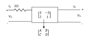
A17)
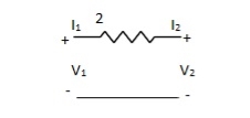


Q18) Find overall Y-parameter?
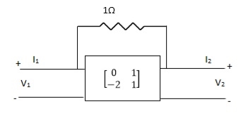
A18)


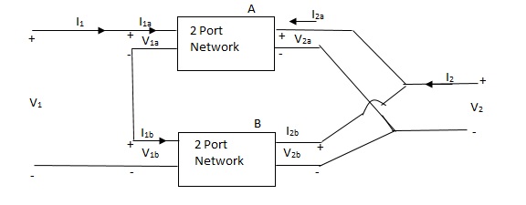
Q19) Explain the series parallel connection of two port network. Derive the equations of h-parameter for the network?
A19)
I1 = I1a = I1b
V1 = V1a +V1b
If two 2-ports are connected in series parallel then overall h-parameter is sum of individual h-parameter
 =
= 
Q20) When the two port network are connected in series which parameter is calculated. Derive and explain?
A20)
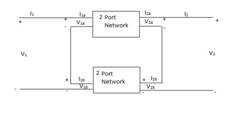
V1 = V1a +V1b
I1 = I1a = I1b
V2 = V2a +V2b
I2 = I2a = I2b
 =
= 
 =
= 
 =
= 
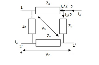
Q21) Obtain the lattice equivalent of a symmetrical T network figure?
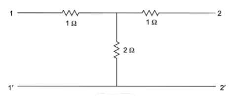
A21) A two-port network can be realised as a symmetric lattice if it is reciprocal and symmetric. The z parameter of the network.
Z11= 3
Z12=Z21= 2 
Z22=3 
Since, Z11=Z22
Z12=Z21
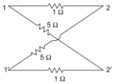
The given network is symmetrical and reciprocal. The parameters of the lattice network are
Za=Z11-Z12=1 
Zb=Z11+Z12=5 
The lattice network is shown below
Q22) Obtain the lattice equivalent of a symmetric p-network shown in Figure?
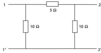
A22) The Z parameters of the given network are
Z11=6  =Z22
=Z22
Z12=Z21=4 
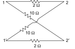
Hence, the parameters of the lattice network are
Za=Z11-Z12=2 
Zb=Z11+Z12= 10 