Unit - 3
Stability Criterion
Q1) Sketch the bode plot for transfer function G(S) = 
A1)
Replace S = j
G(j =
= 
This is type 0 system . So initial slope is 0 dB decade. The starting point is given as
20 log10 K = 20 log10 1000
= 60 dB
Corner frequency  1 =
1 =  = 10 rad/sec
 2 =
2 =  = 1000 rad/sec
Slope after  1 will be -20 dB/decade till second corner frequency i.e
  2 after
  2 the slope will be -40 dB/decade (-20+(-20)) as there are poles
For phase plot
 = tan-1 0.1
 - tan-1 0.001
For phase plot


100 -900
200 -9.450
300 -104.80
400 -110.360
500 -115.420
600 -120.00
700 -124.170
800 -127.940
900 -131.350
1000 -134.420
The plot is shown in figure 1
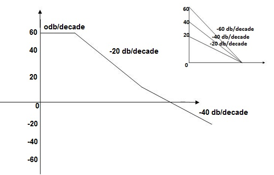
Fig 1 Magnitude Plot for G(S) = 
Q2) For the given transfer function determine G(S) = 
Gain cross over frequency phase cross over frequency phase mergence and gain margin
A2)
Initial slope = 1
N = 1, (K)1/N = 2
K = 2
Corner frequency
 1 =
1 =  = 2 (slope -20 dB/decade
 2 =
2 =  = 20 (slope -40 dB/decade

Phase
 = tan-1
 - tan-1 0.5
  - tan-1 0.05
 = 900- tan-1 0.5
  - tan-1 0.05


1 -119.430
5 -172.230
10 -195.250
15 -209.270
20 -219.30
25 -226.760
30 -232.490
35 -236.980
40 -240.570
45 -243.490
50 -245.910
Finding  gc (gain cross over frequency
M = 
4 =  2 (
2 ( (
(
 6 (6.25
 104) + 0.252
 4 +
4 + 2 = 4
2 = 4
Let  2 = x
2 = x
X3 (6.25 104) + 0.252
 2 + x = 4
X1 = 2.46
X2 = -399.9
X3 = -6.50
For x1 = 2.46
 gc = 3.99 rad/sec(from plot)
For phase margin
PM = 1800 - 
 = 900 – tan-1 (0.5×
 gc) – tan-1 (0.05 ×
  gc)
gc)
= -164.50
PM = 1800 - 164.50
= 15.50
For phase cross over frequency ( pc)
pc)
 = 900 – tan-1 (0.5
  ) – tan-1 (0.05
  )
)
-1800 = -900 – tan-1 (0.5  pc) – tan-1 (0.05
  pc)
pc)
-900 – tan-1 (0.5  pc) – tan-1 (0.05
  pc)
pc)
Taking than on both sides
Tan 900 = tan-1
Let tan-1 0.5  pc = A, tan-1 0.05
  pc = B
 = 00
= 00
 = 0
= 0
1 =0.5  pc 0.05
 pc
pc
 pc = 6.32 rad/sec
The plot is shown in figure 2
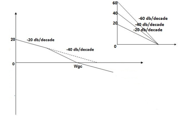
Fig 2 Magnitude Plot for G(S) = 
Q3) For the given transfer function G(S) =  .Plot the rode plot find PM and GM
A3)
T1 = 0.5  1 =
1 =  = 2 rad/sec
Zero so, slope (20 dB/decade)
T2 = 0.2  2 =
2 =  = 5 rad/sec
Pole, so slope (-20 dB/decade)
T3 = 0.1 = T4 = 0.1
 3 =
3 =  4 = 10 (2 pole ) (-40 db/decade)
- Initial slope 0 dB/decade till
 1 = 2 rad/sec
2. From  1 to
1 to 2 (i.e. 2 rad /sec to 5 rad/sec) slope will be 20 dB/decade
3. From  2 to
2 to  3 the slope will be 0 dB/decade (20 + (-20))
4. From  3,
3, 4 the slope will be -40 dB/decade (0-20-20)
Phase plot
 = tan-1 0.5
 - tan-1 0.2
 - tan-1 0.1
 - tan-1 0.1


500 -177.30
1000 -178.60
1500 -179.10
2000 -179.40
2500 -179.50
3000 -179.530
3500 -179.60
GM = 00
PM = 61.460
The plot is shown in figure 9
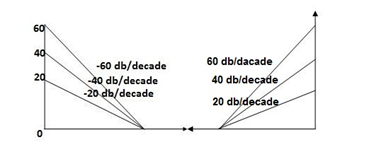
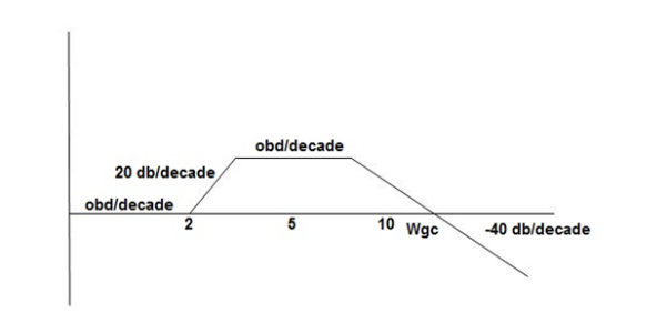
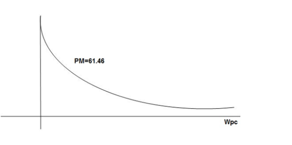
Fig 3 Magnitude and Phase plot for G(S) = 
Q4) For the given transfer function plot the bode plot (magnitude plot) G(S) = 
A4)
Given transfer function
G(S) = 
Converting above transfer function to standard from
G(S) = 
= 
- As type 1 system, so initial slope will be -20 dB/decade
2. Final slope will be -60 dB/decade as order of system decides the final slope
3. Corner frequency
T1 =  ,
,  11= 5 (zero)
T2 = 1,  2 = 1 (pole)
4. Initial slope will cut zero dB axis at
(K)1/N = 10
i.e  = 10
= 10
5. Finding  n and
n and 
T(S) = 
T(S)= 
Comparing with standard second order system equation
S2+2 ns +
ns + n2
n2
 n = 11 rad/sec
 n = 5
n = 5
 11 = 5
 =
=  = 0.27
6. Maximum error
M = -20 log 2
= +6.5 dB
7. As K = 10, so whole plot will shift by 20 log 10 10 = 20 dB
The plot is shown in figure 4
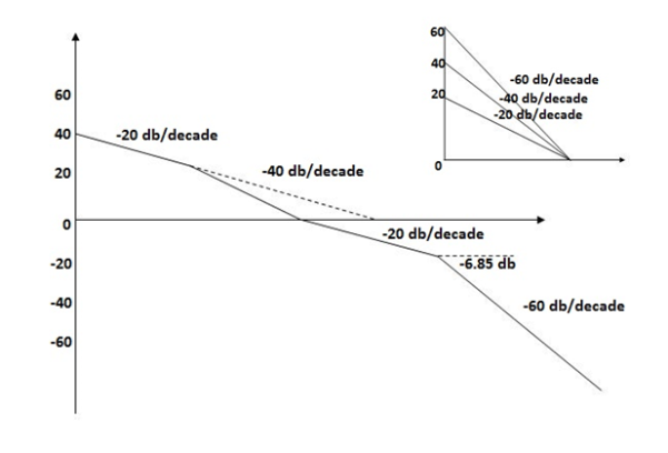
Fig 4 Magnitude plot for G(S) = 
Q5) For the given plot determine the transfer function
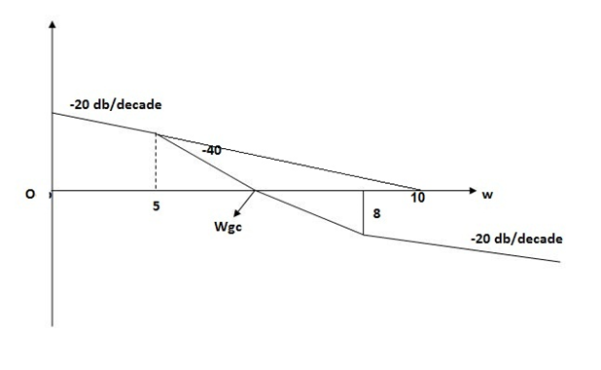
Fig 5 Magnitude plot for Q10
A5)
From figure 5 we can conclude that
- Initial slope = -20 dB/decade so type -1
2. Initial slope alls 0 dB axis at  = 10 so
K1/N N = 1
(K)1/N = 10.
3. Corner frequency
 1 =
1 =  = 0.2 rad/sec
 2 =
2 =  = 0.125 rad/sec
4. At  = 5 the slope becomes -40 dB/decade, so there is a pole at
  = 5 as
Slope changes from -20 dB/decade to -40 dB/decade
5. At  = 8 the slope changes from -40 dB/decade to -20 dB/decade hence
6. is a zero at  = 8 (-40+(+20)=20)
7. Hence transfer function is
T(S) = 
Q6) Sketch the root locus for given open loop transfer function G(S) =  .
.
A6)
1) G(s) = 
Number of Zeros = 0
Number of polls S = (0, -1+j, -1-j) = (3).
1) Number of Branches = max (P, Z) = max (3, 0) = 3.
2) As there are no zeros in the system so, all branches terminate at infinity.
3) As P>Z, branches terminate at infinity through the path shown by asymptotes
Asymptote =  × 180° q = 0, 1, 2………..(p-z-1)
P=3, Z=0.
q= 0, 1, 2.
For q=0
Asymptote = 1/3 × 180° = 60°
For q=1
Asymptote =  × 180°
= 180°
For q=2
Asymptote =  × 180° = 300°
Asymptotes = 60°,180°,300°.
4) Asymptote intersects real axis at centroid
Centroid =
= 
Centroid = -0.66
5) As poles are complex so angle of departure
øD = (2q+1)×180°+ø
ø = ∠Z –∠P.
Calculating ø for S=0
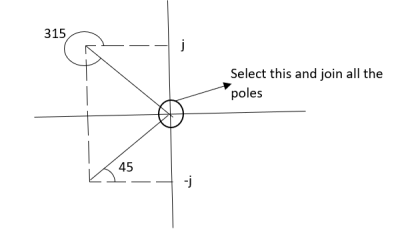
Join all the other poles with S=0
ø = ∠Z –∠P.
= 0-(315°+45°)
= -360°
ØD = (2q + 1)180 + ø.
= 180° - 360°
ØD = -180° (for q=0)
= 180° (for q=1)
=540° (for q=2)
Calculation ØD for pole at (-1+j)
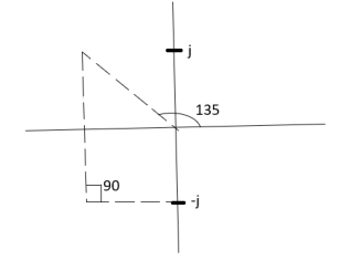
ø = ∠Z –∠P.
= 0 –(135°+90°)
= -225°
ØD = (2q+1) 180°+ø.
= 180-225°
= -45°
ØD = -45° (for q = 0)
= 315° (for q = 1)
= 675° (for q =2)
6) The crossing point on imaginary axis can be calculated by Routh Hurwitz the characteristic equation is.
1+G(s) H (s) = 0
1+
S (S2+2s+2)+k = 0
S3+2s2+2s+K = 0
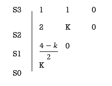
For stability  > 0. And K > 0.
0<K<2.
So, when K=2 root locus crosses imaginary axis
S3 + 2S2 + 2S + 2 =0
For k
Sn-1 = 0 n: no. Of intersection
S2-1 = 0 at imaginary axis
S1 = 0
 = 0
= 0
K<4
For Sn = 0 for valve of S at that K
S2 = 0
2S2 + K = 0
2S2 + 2 = 0
2(S2 +1) = 0
32 = -2
S = ± j 
The root locus plot is shown in figure below.
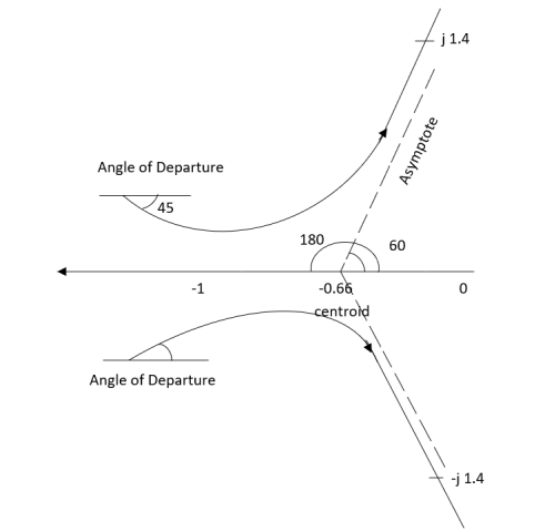
Q7) Sketch the root locus plot for the following open loop transfer function
G(s) = 
A7)
- Number of zero = 0, number of poles = 3
2. As P>Z, branches will terminates at infinity
3. There are no zeros so all branches will terminate at infinity.
4. The path for the branches is shown by asymptote
Asymptote =  ×180°. q=0,1,………p-z-1
P=3, Z=0
q= 0,1,2.
For q = 0
Asymptote =  × 180° = 60.
For q=1
Asymptote =  × 180° = 180°
For q=2
Asymptote =  × 180° = 300°
5. Asymptote intersect real axis at centroid
Centroid = 
=  = -1
= -1
6. As root locus lies between poles S= 0, and S= -1
So, calculating breakaway point.
 = 0
= 0
The characteristic equation is
1+ G(s) H (s) = 0.
1+  = 0
= 0
K = -(S3+3S2+2s)
 = 3S2+6s+2 = 0
3s2+6s+2 = 0
S = -0.423, -1.577.
So, breakaway point is at S=-0.423
Because root locus is between S= 0 and S= -1
7. The intersection of root locus with imaginary axis is given by Routh criterion.
Characteristics equation is
S3+3S3+2s+K = 0
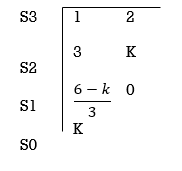
For k
Sn-1= 0 n: no. Of intersection with imaginary axis
n=2
S1 = 0
 = 0
= 0
K < 6 Valve of S at the above valve of K
Sn = 0
S2 = 0
3S2 + K =0
3S2 +6 = 0
S2 + 2 = 0
S = ±  j
j
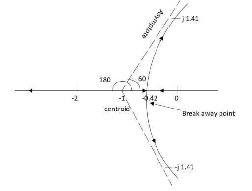
The root locus plot is shown in fig.
Q8) Plot the root locus for the given open loop transfer function
G(s) = 
A8)
- Number of zeros = 0 number of poles = 4
P = (S=0,-1,-1+j,-1-j) = 4
2. As P>Z all the branches will terminated at infinity.
3. As no zeros so all branches terminate at infinity.
4. The path for branches is shown by asymptote.
Asymptote =  q = 0,1,…..(Þ-z-1)
q=0,1,2,3. (P-Z = 4-0)
For q=0
Asymptote =  ×180° =45°
For q=1
Asymptote =  ×180° =135°
For q=2
Asymptote =  ×180° =225°
For q=3
Asymptote =  ×180° =315°
5. Asymptote intersects real axis at unmarried
Centroid = 
Centroid =  =
=  = -0.75
6) As poles are complex so angle of departure is
ØD = (2q+1) ×180 + ø ø = ∠Z –∠P.
Calculating Ø for S=0
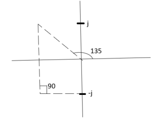
ø = ∠Z –∠P.
= 0 –[315° + 45°]
Ø = -360°
For q = 0
ØD = (2q+1) 180° + Ø
= 180 - 360°
ØD = -180°
b) Calculating Ø for S=-1+j
ø = ∠Z –∠P.
= 0-[135° + 90° + 90°]
Ø = -315°
For q=0
ØD= (2q+1) 180° +Ø
= 180° -315°
ØD = -135°
ØD for S=1+j will be ØD = 45°
7) As the root locus lie between S=0 and S=-1
So, the breakaway point is calculated

1+ G(s)H(s) = 0
1+  = 0
= 0
(S2+S)(S2 +2S+2) + K =0
K = -[S4+S3+2s3+2s2+2s2+2s]
 = 4S3+9S2+8S+2=0
S = -0.39, -0.93, -0.93.
The breakaway point is at S = -0.39 as root locus exists between S= 0 and S=-1
8) Intersection of root locus with imaginary axis is given by Routh Hurwitz
I + G(s) H(s) = 0
K+S4+3S3+4S2+2S=0
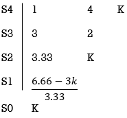
For system to be stable
 >0
>0
6.66>3K
0<K<2.22.
For K = 2.22
3.3352+K =0
3.3352 + 2.22 = 0
S2 = -0.66
S = ± j 0.816.
The root locus plot is shown in figure 6.
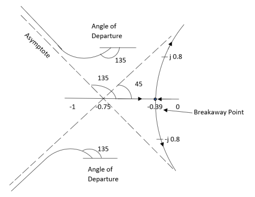
Figure-6
Q9) Plot the root locus for open loop system G(s) = 
A9)
1) Number of zero = 0 number of poles = 4 located at S=0, -2, -1+j, -1-j.
2) As no zeros are present so all branches terminated at infinity.
3) As P>Z, the path for branches is shown by asymptote
Asymptote = 
q = 0,1,2……p-z-1
For q = 0
Asymptote = 45°
q=1
Asymptote = 135°
q=2
Asymptote = 225°
q=3
Asymptote = 315°
4) Asymptote intersects real axis at centroid.
Centroid = 
= 
Centroid = -1.
5) As poles are complex so angle of departure is
ØD=(2q+1)180° + Ø
ø = ∠Z –∠P
= 0-[135°+45°+90°]
= 180°- 270°
ØD = -90°
6) As root locus lies between two poles so calculating point. The characteristic equation is
1+ G(s)H(s) = 0
1+ = 0.
= 0.
K = -[S4+2S3+2S2+2S3+4S2+4S]
K = -[S4+4S3+6S2+4S]
 = 0
= 0
 = 4s3+12s2+12s+4=0
S = -1
So, breakaway point is at S = -1
7) Intersection of root locus with imaginary axis is given by Routh Hurwitz.
S4+4S3+6S2+4s+K = 0
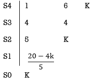
 ≤ 0
≤ 0
K≤5.
For K=5 valve of S will be.
5S2+K = 0
5S2+5 = 0
S2 +1 = 0
S2 = -1
S = ±j.
The root locus is shown in figure 7.
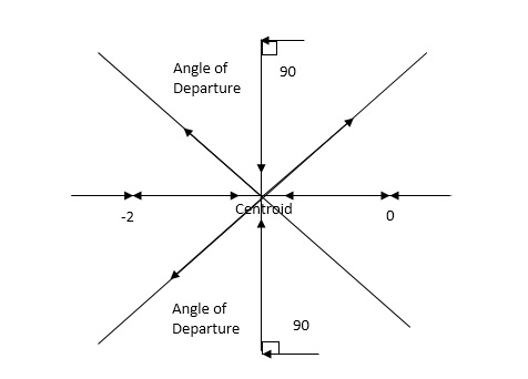
Figure-7
Q10) Plot the root locus for open loop transfer function G(s) = 
A10)
- Number of zeros = 0. Number of poles = 4 located at S=0, -3, -1+j, -1-j.
2. As no. Zero so all branches terminate at infinity.
3. The asymptote shows the both to the branches terminating at infinity.
Asymptote =  q=0,1,….(p-z).
For q = 0
Asymptote = 45
For q = 1
Asymptote = 135
For q = 2
Asymptote = 225
For q = 3
Asymptote = 315
(4). The asymptote intersects real axis at centroid.
Centroid = ∑Real part of poles - ∑Real part of zero / P – Z
= [-3-1-1] – 0 / 4 – 0
Centroid = -1.25
(5). As poles are complex so angle of departure
φD = (29 + 1)180 + φ

ø = ∠Z –∠P.
= 0 – [ 135 + 26.5 + 90 ]
= -251.56
For q = 0
φD = (29 + 1)180 + φ
= 180 – 215.5
φD = - 71.56
(6). Break away point dk / ds = 0 is at S = -2.28.
(7). The intersection of root locus on imaginary axis is given by Routh Hurwitz.
1 + G(S)H(S) = 0
K + S4 + 3S3 + 2S3 + 6S2 + 2S2 + 6S = 0
S4 1 8 K
S3 5 6
S2 34/5 K
S1 40.8 – 5K/6.8
K ≤ 8.16
For K = 8.16 value of S will be
6.8 S2 + K = 0
6.8 S2 + 8.16 = 0
S2 = - 1.2
S = ± j1.09
The plot is shown in figure 8.
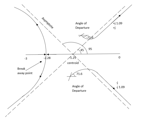
Figure-8
Q11) Sketch the root locus for open loop transfer function. G(S) = K(S + 6)/S(S + 4)
A11)
- Number of zeros = 1(S = -6)
Number of poles = 2(S = 0, -4)
2. As P > Z one branch will terminate at infinity and the other at S = -6.
3. For Break away and breaking point
1 + G(S)H(S) = 0
1 + K(S + 6)/S(S + 4) = 0
Dk/ds = 0
S2 + 12S + 24 = 0
S = -9.5, -2.5
Breakaway point is at -2.5 and Break in point is at -9.5.
4. Root locus will be in the form of a circle. So finding the centre and radius. Let S = + jw.
G( + jw) = K( + jw + 6)/( + jw)( + jw + 4 ) = +- π
Tan-1 w/ + 6 - tan-1 w/ – tan-1 w / + 4 = - π
Taking tan of both sides.
w/ + w/ + 4 / 1 – w/ w/ + 4 = tan π + w / + 6 / 1 - tan π w/ + 6
w/ + w/ + 4 = w/ + 6[ 1 – w2 / ( + 4) ]
(2 + 4)( + 6) = (2 + 4 – w2)
2 2 + 12 + 4 + 24 = 2 + 4 – w2
22 + 12 + 24 = 2 – w2
2 + 12 – w2 + 24 = 0
Adding 36 on both sides
( + 6)2 + (w + 0)2 = 12
The above equation shows circle with radius 3.46 and center(-6, 0) the plot is shown in figure 9.

Figure-9
Q12) Determine the stability of the system represent by following characteristic equations using Routh criterion
1) S4 + 3s3 + 8s2 + 4s +3 = 0
2) S4 + 9s3 + 4S2 – 36s -32 = 0
A12)
1) S4+3s3+8s2+4s+3=0
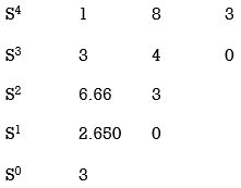
No sign change in first column to no rows on right half of S-plane system stable.
2) S4 + 9s3 + 4S2 – 36s -32 = 0
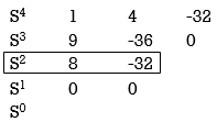
Special case II of Routh Hurwitz criterion forming auxiliary equation
A1 (s) = 8S2 – 32 = 0
 = 16S – 0 =0
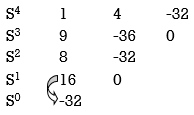
One sign change so, one root lies on right half S-plane hence system is unstable.
Q13) For using feedback open loop transfer function G(s) = 
Find range of k for stability
A13)
Findlay characteristics equation
CE = 1+G (s) H(s) = 0
H(s) =1 using feedback
CE = 1+ G(s)
1+  = 0
= 0
S(S+1)(S+3)(S+4)+k = 0
(S2+5)(S2+7Sα12)αK = 0
S4α7S3α1252+S3α7S2α125αK = 0
S4+8S3α19S2+125+k = 0
By Routh Hurwitz Criterion
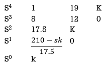
For system to be stable the range of K is 0< K <  .
.
Q14) The characteristic equation for certain feedback control system is given S4 +4S3+ 12S2+36S+K. Find range of K for system to be stable.
Q15)
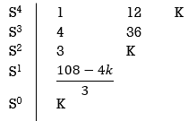
S4+4S3α12S2+36SαK = 0
For stability K>0
 > 0
> 0
K < 27
Range of K will be 0 < K < 27
Q16) Check if all roots of equation S3+6S2+25S+38 = 0, have real pole more negative than -1.
A15)
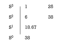
No sign change in first column, hence all roots are in left half of S-plane.
Replacing S = Z-1. In above equation
(Z-1)3+6(Z-1)2+25(Z-1)+38 = 0
Z3+ Z23+16Z+18=0
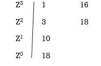
No sign change in first column roots lie on left half of Z-plane hence all roots of original equation in S-domain lie to left half 0f S = -1
Q17) What is effect of addition of poles and zeros on a closed loop system?
A16) Effect of addition of zeros
1) The root locus shifts away from imaginary axis.
2) Stability of system increases.
3) The settling time decreases.
4) The gain margin increases.
5) The system becomes less oscillatory.
Effect of Addition of Poles:
1) The root locus is shifted towards imaginary axis.
2) The system becomes oscillatory.
3) The stability of system decreases.
4) The settling time increases.
5) The range of k reduces.
Q18) Explain angle and magnitude criterion for root locus?
A17) Angle condition:
LG(S)H(S) = +-1800(2 KH) (K = 1,2,3,--)
If angle is odd multiple of 1800 it satisfies above condition.
Magnitude condition:
| G(S)H(S) = 1 | at any point on root locus. The magnitude condition can be applied only if angle condition is satisfied.
Q19) Taking any example explain the special case of Routh stability?
A18) Determine the stability of the system with characteristic equation S4+8S3+18S2+16S+S = 0
Sol: Arrange in rows.
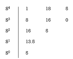
For row S2 first element
S1 =  = 16
= 16
Second terms =  = 5
= 5
For S1
First element =  = 13.5
For S0
First element =  = 5
= 5
As there is no sign change for first column so all roots are is left half of S-plane and hence system is stable.
Special Cases of Routh Hurwitz Criterions
I) When first element of any row is zero.
In this case the zero is replaced by a very small positive number E and rest of the array is evaluated.
Eg.(1) Consider the following equation
S3+S+2 = 0
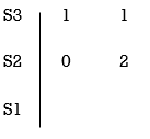
Replacing 0 by E

Now when E  0, values in column 1 becomes
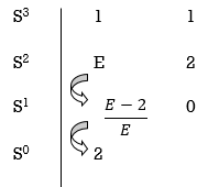
Two sign changes hence two roots on right side of S-plans
II) When any one row is having all its terms zero.
When array one row of Routh Hurwitz table is zero, it shown that the X is attests one pair of roots which lies radially opposite to each other in this case the array can be completed by auxiliary polynomial. It is the polynomial row first above row zero.
Consider following example
S3 + 5S2 + 6S + 30
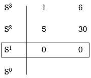
For forming auxiliary equation, selecting row first above row hang all terms zero.
A(s) = 5S2 e 30
 = 10s e0.
Again forming Routh array
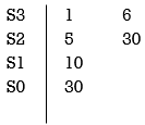
No sign change in column one the roots of Auxiliary equation A(s)=5s2+ 30-0
5s2+30 = 0
S2 α 6= 0
S = ± j 
Both lie on imaginary axis so system is marginally stable.