Unit - 4
The Energy Equation and its Application
Q1) Describe the fluid motion using equations.
A1)
Two methods are used to explain fluid motion. They are the Lagrangian Method and the Eulerian Method, respectively. A single fluid particle is followed during its motion in the Lagrangian approach, and its velocity, acceleration, density, and other properties are described. The velocity, acceleration, pressure, density, and other parameters are described at a point in the flow field using the Eulerian Method. In fluid mechanics, the Eulerian method is widely employed.
Langragian method
In this method, the observer concentrates on the movement of a single particle.
The path taken by the particle and the changes in its velocity and acceleration are studied.
In the cartesian system the position of the fluid particle in space (x, y, z) at any time t from its position (a, b, c) at time t=0 shall be given as,
x = f1(a, b, c, t)
y = f2(a, b, c, t)
z = f3(a, b, c, t)
The velocity and acceleration components (obtained by taking derivations with respect to time) are given by,
Velocity components:


Acceleration component:


At any point, the resultant velocity or acceleration shall be the resultant of these components of the respective quantity at that point.
Resultant velocity,

Acceleration,

Similarly, other quantities like pressure, density, etc. can be found.
Eulerian Method
In Eulerian method, the observer concentrates on a point in the fluid system. Velocity, acceleration, and other characteristics of the fluid at that point are studied.
This method is almost exclusively used a fluid mechanics, especially because of its mathematical simplicity. The velocity at any point (x, y, z) can be written as
u = f1(x, y, z, t)
v = f2(x, y, z, t)
w = f3(x, y, z, t)
The components of acceleration of the fluid particle can be worked out by partial differentiation as follows:


Now, resultant velocity:

Acceleration,

Q2) Explain the type of fluid flows.
A2)
- Steady and Unsteady flows
Steady flow – The type of flow in which the fluid characteristics like velocity, pressure, density, etc. at a point do not change with time is called steady flow.
Example: Flow through a prismatic or non-prismatic conduct at a constant flow rate Q m3/s is steady.
Mathematically,

Unsteady flow: It is that type of flow in which the velocity, pressure or density at a point change w.r.t. Time.
E.g.: the flow in a pipe whose value is being opened or closed gradually.
Mathematically, 
- Uniform and Non-uniform Flows
Uniform flow – The type of flow, in which the velocity at any given time does not change with respect to space is called uniform flow.
E.g.: Flow through a straight prismatic conduit.
Mathematically,  when t = constant
Non-uniform flow – It is that type of flow in which the velocity at any given time changes with respect to space.
E.g.: Flow through non-prismatic conduit.
Mathematically,  when t = constant
- One, two & Three-dimensional flow
One dimensional flow – it is that type of flow in which the flow parameter such as velocity is a function of time and one space coordinate.
E.g.: Flow in a pipe where average flow parameters are considered for analysis.
Mathematically, u = f(x), v = 0 & w = 0
Two-dimensional Flow – The flow in which the velocity is a function of time, and two rectangular space coordinates is called two-dimensional flow.
E.g.: Flow between parallel plates of infinite extent.
Mathematically, u = f1(x, y) v = f2(x, y) & w = 0
Three-dimensional flow – It is that type of flow in which the velocity is a function of time and three mutually perpendicular directions.
E.g.: Flow in a converging or diverging pipe or channel.
Mathematically, u = f1(x, y, z) v = f2(x, y, z) & w = f3(x, y, z)
- Rotational and Irrotational Flows
Rotational Flow -A flow said to be rotational if the fluid particles while moving in the direction of flow rotate about their mass centres.
E.g.; Motion of liquid in a rotating tank.
Irrotational flow - A flow said to be rotational if the fluid particles while moving in the direction of flow do not rotate about their mass centres.
E.g.: Flow above a drain hole of a stationary tank or a water basin.
- Laminar and Turbulent Flows
Laminar Flow – A Laminar flow is one in which paths taken by the individual particles do not cross one another and move along well-defined path.
E.g.: Flow of blood in veins and arteries.
Turbulent Flow – A turbulent flow is that flow in which fluid particles move in a zig zag way.
E.g.: High velocity flows in conduit of large size.
- Compressible & Incompressible Flow
Compressible Flow – It is that type of Flow in Which the density ( ) of the fluid changes from point to point.
E.g.: Flow of gases through orifices, nozzles, gas turbines, etc.
Mathematically, 
Incompressible Flow – It is that type of flow in which density is constant for the fluid flow. Liquids are generally considered flowing incompressible.
E.g.: subsonic aerodynamics.
Mathematically, 
- Subcritical, Critical & Supercritical Flow
Subcritical flow– When Froude’s number is less than one the flow is known as subcritical flow.
Mathematically, Fr 
Critical flow– When Froude’s number is equal to one the flow is known as subcritical flow.
Mathematically, Fr 
Supercritical flow– When Froude’s number is more than one the flow is known as subcritical flow.
Mathematically, Fr 
Q3) Derive the continuity equation for 1D flow.
A3)
The continuity equation is based on the principle of conservation of mass. It states as follows
If no fluid is added or removed from the pipe in any length, then the mass passing across different sections shall be same.
Consider two cross-sections of a pipe as shown in fig.
Let, A1 & A2 = Areas of the pipe at section 1-1 & section 2-2 respectively.
V1 & V2 = Velocities of the fluid at section 1-1 & section 2-2 respectively.
 1 &
1 &  2 = Densities of the fluid at section 1-1 & section 2-2 respectively.
Total quantity of fluid passing through the section 1-1 = ρ1A1V1
Total quantity of fluid passing through the section 2-2 = ρ2A2V2
From the law of conservation of matter
ρ1 A1 V1 = ρ2 A2 V2
In case of incompressible fluids  1 =
1 = 2
2

Q4) Derive the continuity equation for 3D flow.
A4)
Considers a fluid element (control volume)- parallelepiped with sides dx, dy and dz as shown in fig.
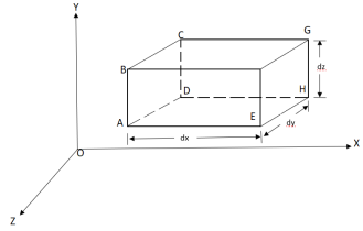
Let,  = Mass density of the fluid at a particular instant
u, v, w= components of velocity of flow entering the three faces of the parallelepiped.
Rate of Mass of fluid entering the face ABCD


Rate of Mass of fluid leaving the lace FEGH

:. Mass accelerated per unit time, due to flow in x-direction


Similarly, the gain in fluid mass per unit time in the parallelepiped due to flow in Y and Z- direction.


The total gain in fluid mass per unit for fluid along three co-ordinate axes

Rate of change of mass of the parallelepiped (control volume)

From Equation 1& 2

Simplification and rearrangement of teams would reduce the above expression to

This eq. Is the general equation of continuity in three dimension and is applicable to any type of flow and for any fluid whether compressible as incompressible
For steady flow ( =0) incompressible fluids (
 = constant) the equation reduces to

Q5) Explain velocity potential & stream function.
A5)
The velocity potential is defined as scaler function of space and time such that its negative derivative with respect to any directions gives the fluid velocity in that direction.
It is denoted by Ø (phi)
Thus, mathematically the velocity potential is defined as
Ø = f (x, y, z, t)
And Ø = f (x, y, z)


Where u, v and w are the components of velocity in the x, y and z directions respectively.
The negative sign signifies that Ø decreases with an increase in the values of x, y and z. In other words, it indicates that the flow is always in the direction of decreasing Ø.
Stream function
It is defined as the scalar function of space and time such that its partial derivative with respect to any direction gives the velocity component at right angles to that direction.
It is denoted by Ψ (psi) and defined only for two-dimensional flow.
Mathematically, for ready flow it is defined as Ψ = f (x, y) such that

And

Q6) Explain types of displacements in fluids.
A6)
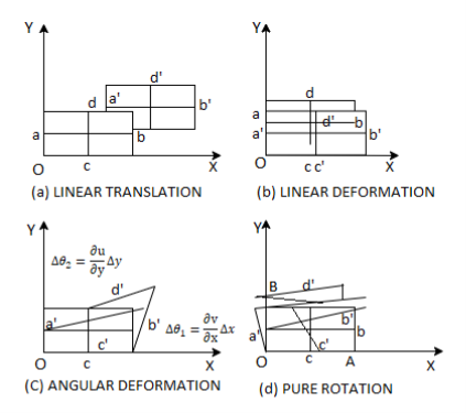
When a fluid particle moves, it can experience any or all of the four types of displacements listed below.
- Linear translation or pure translation
It is defined as the physical movement of a fluid element from one position to another.
“Two axes ab and cd represented in new positions by a'b' and c' d' are parallel.”
- Linear deformation
It is defined as the linear deformation of a fluid element when the element moves. The element's axes are parallel in the deformed and un-deformed positions, but their lengths differ.
- Angular rotation
It is defined as the average change in the angle contained by two adjacent sides.


- Rotation
The movement of a fluid element in such a way that both of its axes (horizontal and vertical) rotate in the same direction is referred to as lt.


Q7) Derive Bernoulli’s theorem from Euler’s equation.
A7)
Consider a cylindrical element,


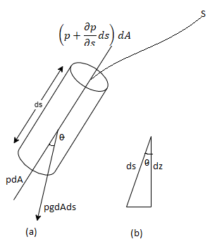


The resultant force on the fluid element in the direction of s must be equal to the mass of fluid element x acceleration in the direction s.


Now,


So,


Dividing by 


As,


Q8) Explain pitot tube in brief.
A8)
Pitot probes (also known as Pitot tubes) and Pitot-static probes are frequently used for flow rate measurement and are named after the French engineer Henri de Pitot (1695–1771). A Pitot probe is just a tube with a pressure tap at the stagnation point that measures stagnation pressure, whereas a Pitot-static probe has a stagnation pressure tap as well as many circumferential static pressures taps that measure both stagnation and static pressures.
The Pitot-static probe uses the Bernoulli equation to calculate local velocity by detecting the pressure differential. It is made out of a thin double-tube that is aligned with the flow and is coupled to a differential pressure metre. At the nose, the inner tube is totally exposed to flow, therefore it monitors the stagnation pressure there (point 1). The outer tube is sealed at the nose but has openings on the side of the outer wall (point 2), which allows it to measure static pressure.
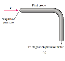
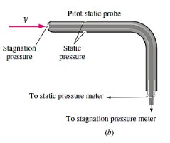
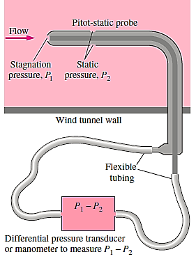
The Bernoulli equation is suitable for incompressible flow with sufficiently high velocities (such that frictional effects between points 1 and 2 are minimal) and can be stated as,

Noting that,

Since the static pressure holes of the Pitot-static probe are arranged circumferentially around the tube &  because of the stagnation
Conditions
The flow velocity 

The volume flow rate can be calculated if the velocity is measured at a site where the local velocity equals the average flow velocity.

Because it has no moving parts, the Pitot-static probe is a simple, low-cost, and very reliable gadget. It also creates a very tiny pressure decrease and normally has little effect on the flow. However, it is critical that it is properly aligned with the flow in order to avoid major errors caused by misalignment.
In addition, the difference between the static and stagnation pressures (the dynamic pressure) is proportional to the fluid density and the square of the flow velocity. It can be used to determine the velocity of liquids as well as gases. Given the low density of gases, the flow velocity must be sufficiently high for a measurable dynamic pressure to emerge when the Pitot-static probe is employed for gas flow.
Q9) Explain the principle of Venturi meter.
A9)
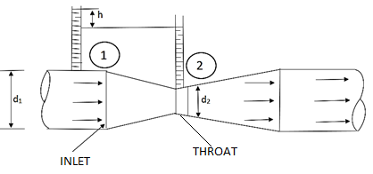
The differential generating flowmeter, often known as a Venturi, has a long history of application in a variety of fields. The Venturi is one of the most widely used flowmeters due to its simplicity and dependability. The Venturi can monitor fluid flowrates with minimal total pressure loss because it has no moving parts or sudden flow limitations.
The Bernoulli effect is at the heart of the Venturi flowmeter's operation. The Venturi determines the flow rate of a fluid by lowering the cross-sectional flow area in the flow channel and creating a pressure difference. Following the generation of the pressure difference, the fluid is routed via a pressure recovery exit section, which recovers up to 80% of the differential pressure generated at the throat.
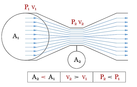
The fluid, whether liquid or gaseous, enters the Venturi at the position with the cross-sectional area A1, pressure P1, and velocity V1 in the illustration above. These qualities combine to form the fluid's potential and kinetic energy at a single point. In a closed system, energy is conserved, which means that the sum of potential and kinetic energy at one point must match the sum of potential and kinetic energy at all other points in the system.
If potential energy falls at one location, kinetic energy must rise proportionately at the same site. The fluid now reaches the Venturi's throat through a region A2 that is smaller than A1. Because mass cannot be generated or destroyed in a closed system (the law of conservation of mass states that what goes in must come out), the volumetric flowrate at area A1 must match the volumetric flowrate at area A2.
If A2 has a smaller area than A1, the fluid must travel faster to maintain the same volumetric flowrate. According to Bernoulli's equation, an increase in velocity causes a drop in pressure. As a result, knowing the pressure and cross-sectional area at two points allows one to compute the fluid's velocity. The flowrate can be calculated using the fluid's velocity and density.
Q10) What is the use of rotameter?
A10)
The variable-area flowmeter, also known as a rotameter or float metre, is a simple, dependable, inexpensive, and easy-to-install flowmeter with little pressure drop and no electrical connections that provides a direct reading of flow rate for a wide range of liquids and gases. A variable-area flowmeter is constructed up of a vertically tapered conical transparent tube made of glass or plastic with a free-moving float within.
The float rises within the tapered tube as fluid flows through it until a point where the float weight, drag force, and buoyancy force balance each other, and the net force acting on the float is zero. Simply match the position of the float against the graduated flow scale outside the tapered transparent tube to ascertain the flow rate.
High winds have been known to bring down trees, smash power lines, and blow hats and umbrellas away. This is due to the fact that the drag force increases as the flow velocity increases. The float's weight and buoyancy force are constant, but the drag force varies with flow velocity. In addition, owing of the increased cross-sectional area, the velocity along the tapered tube reduces in the flow direction.
The float settles at a specific velocity that provides enough drag to balance the float's weight and buoyancy force, and the location where this velocity occurs around the float is where the float settles. The tube's degree of tapering can be adjusted so that the vertical rise changes linearly with flow rate, allowing the tube to be linearly calibrated for flow rates. The fluid can also be seen flowing through the clear tube.
Variable-area flowmeters come in a variety of shapes and sizes. The previously mentioned gravity-based flowmeter must be installed vertically, with fluid entering from the bottom and exiting from the top. The drag force is balanced by the spring force in spring-opposed flowmeters, which can be mounted horizontally. Instead of a float, a loose-fitting piston is used in another form of flowmeter.
Variable-area flowmeters have a typical accuracy of +/- 5%. As a result, these flowmeters are not suitable for applications requiring precise measurements. Some manufacturers, on the other hand, claim accuracies of the order of 1%. Furthermore, because these metres rely on visual inspection of the float's location, they cannot be used to measure the flow rate of fluids that are opaque or unclean, or fluids that cover the float, as these fluids prevent visual inspection. Finally, glass tubes are prone to breaking, posing a safety risk when handling dangerous fluids. Variable-area flowmeters should be deployed in low-traffic sites in such applications.
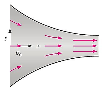
Q11) Consider steady, incompressible, two-dimensional flow through a converging duct. A simple approximate velocity field for this flow is


Note that this equation ignores viscous effects along the walls but is a reasonable approximation throughout the majority of the flow field. Calculate the material acceleration for fluid particles passing through this duct. Give your answer in two ways: (1) as acceleration components ax and ay and (2) as acceleration vector 
A11)
The velocity field is,

The acceleration field components are,


Where the unsteady terms are zero since this is a steady flow, and the terms with w are zero since the flow is two dimensional
Material acceleration components:


In terms of a vector,
Material acceleration vector:

Q12) A steady, incompressible, two-dimensional velocity field is given by the following components in the xy-plane


Calculate the acceleration field and calculate the acceleration at
The point (-2,3).
A12)


At (-2,3)


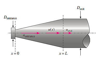
Q13) Consider steady flow of air through the diffuser portion of a wind tunnel. Along the centreline of the diffuser, the air speed decreases from entrance to exit as sketched. Measurements reveal that the centerline air speed decreases parabolically through the diffuser. Write an equation for centreline speed u(x), based on the parameters given here, from x = 0 to x = L.
A13)
General equation for a parabola in x is,

Boundary conditions,


By inspection,


So,

Q14) For the velocity field of

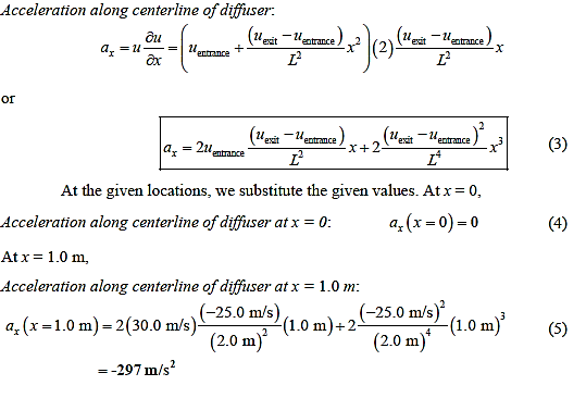
Calculate the fluid acceleration along the diffuser centreline as a function of x and the given parameters.


Calculate the acceleration at,

A14)

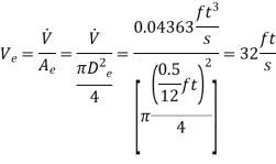
Q15) To fill a 20-gal bucket, a garden hose with a nozzle is utilised. The hose has a 1 in inner diameter that narrows to 0.5 in at the nozzle exit. Determine (a) the volume and mass flow rates of water through the hose, (b) how long it will take to fill the bucket with water, and (c) the average velocity of water at the nozzle exit if the hose's average velocity is 8 ft/s.
A15)

Volume flow rate,

Mass flow rate,

Time taken to fill a 20-gallon bucket,

The average discharge velocity of water at the nozzle exit is,
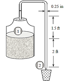
Q16) Large water bottles are used to meet an office's drinking water needs. One end of a 0.25-inch plastic hose is inserted into the bottle, which is placed on a high stand, while the other end, which has an on/off valve, is kept 2 feet below the bottle's bottom. Determine how long it will take to fill an 8-oz glass (= 0.00835 ft3) (a) when the bottle is first opened and (b) when the bottle is almost empty if the water level in the bottle is 1.5 ft when it is full.
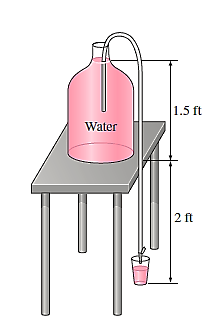
A16)
Point 1 at free surface of water in the bottle.
Point 2 at exit of the tube.


As, Full bottle


As, Empty bottle


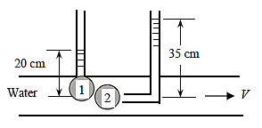
Q17) A piezometer and a Pitot tube are tapped into a horizontal water pipe with a diameter of 3 cm, and the height of the water columns is measured to be 20 cm in the piezometer and 35 cm in the Pitot tube (both measured from the top surface of the pipe). Calculate the velocity in the pipe's centre.
A17)


Q18) A venturi meter has an area ratio 9.1, the large diameter being 30 cm. During the flow, the recorded pressure head in the large section is 7.75 m and that at the throat is 5.5 m. Find the discharge through the meter if C,0.98.
A18)


Discharge of inlet
d1 = 0.3 m
Pressure at inlet 
Pressure head at throat 
Coefficient of discharge Cd, = 0.98
Area


Pressure head

Discharge


Q19) The top and bottom diameters of a 2m long vertical tapering pipe are 100 mm and 50 mm respectively. Water flows down the pipe at 30 liters por second. Find the pressure difference between the two ends of the pipe.
A19)
Q = 30 Lps = 0.03 m³/sec,
d1 = 0.05 m. d₂ = 0.1 m, z₁ = 0, z₂ = 2 m
Area


By continuity equation,


By Bernoulli's equation


:. The pressure difference between two ends of pipe is 10.415x 10³ Pa
Q20) A pipe has a length of 200 m with a slope of 1 in 100. The diameter of pipes changes from 1.0 m at higher end to 0.5 m at lower end. Find the pressure at the lower end if the discharge flowing through pipe is 5.00 m/min and pressure at higher end is 45 kN/m².
A20)
L = 200 m,
P₁ =45 kN/m²
Slope = 1 in 100. z₁ = 0,
d₂ -0.5 m
Q = 5 m/min =5/60 = 0.0833 m/sec
To find: P₂
Slope of pipe is 1 in 100


(Since it is below z₁
i.e., datum, it is considered negative) = -2m
By continuity equation


By Bernoulli's equation


Multiplying by 9.81
