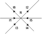
The algebraic sum of currents meeting at a junction or node in an electric circuit is zero ② or the summation of all incoming currents is always equal to the summation of all outgoing current in an electrical network. Explanation
Assuming the incoming current to be positive and outgoing current negative we have
ie
Kirchhoff’s Voltage Law (KVL) statement: the algebraic summation of all Voltage in any closed circuit or mesh of loop zero. i.e. ∑ Voltage in closed-loop = 0 the summation of the Voltage rise (voltage sources) is equal to the summation of the voltage drops around a closed loop in 0 circuits for an explanation from here determination of sigh and direction of currents (Don’t write in exams just for understanding)
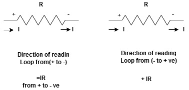
current entering a resistor is +ve and leaving should be –ve now
Potential Rise Potential Drop
We are reading from +V to –V we are reading from –V to +V
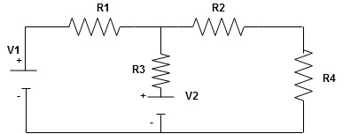
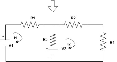
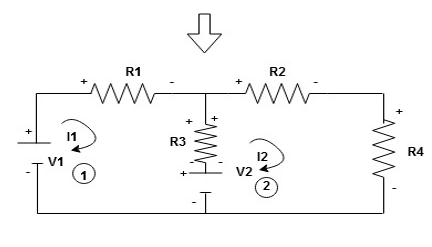
Given Circuit
First, identify no of loops and assign the direction of current flowing in the loop Note: no of loops in-circuit = No, of unknown currents = no, of equations in the circuit
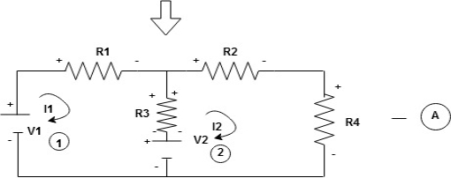
Note: keep loop direction and current direction same ie either clockwise or anticlockwise for all loops I1 I2 Now according to the direction of direction assign signs (+ve to –ve) to the resistors
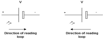
Note: voltage sources (V) polarities do not change is constant. Note: for common resistor between 2 loops appearing in the circuit like R3 give signs according to separate loops as shown
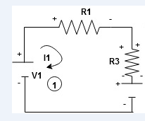
When considering only loop no 1 (+ R3 - )
- B
Now consider diagram A and write equations Two loops
Apply KVL for loop ① [B. Diagram ] (+ to drop -) = - sign and (- to rise +) = + sign
- -(
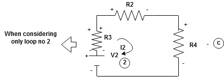
Similarly for loop no. 2 currents flowing is
Consider loop no. 1 apply KVL - - Consider loop no. 2 apply KVL - - After solving equation ① and ② we will get branch current
|
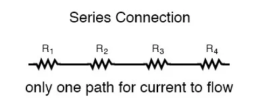
Q2) Explain series and parallel circuit? A2) Series and parallel circuit The basic idea of a “series” connection is that components are connected end-to-end in a line to form a single path through which current can flow:
Series connection
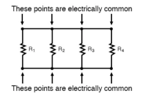
Parallel connection:
The basic idea of a “parallel” connection, on the other hand, is that all components are connected across each other’s leads. In a purely parallel circuit, there are never more than two sets of electrically common points, no matter how many components are connected. There are many paths for current flow, but only one voltage across all components:
|
Q3) Explain current and voltage division rule? A3) A parallel circuit acts as a current divider as the current divides in all the branches in a parallel circuit, and the voltage remains the same across them. The current division rule determines the current across the circuit impedance. The current division is explained with the help of the circuit shown below: The current I has been divided into I1 and I2 into two parallel branches with the resistance R1 and R2 and V is the voltage drop across the resistance R1 and R2.
As we know, V = IR ……..(1) Then the equation of the current is written as: I1 = V/R1 and I2 = V /R2 Let the total resistance of the circuit be R and is given by the equation shown below: R = R1R2/ R1 + R2 Equation (1) can also be written as: I = V/R ……….(3) Now, putting the value of R from the equation (2) in the equation (3) we will get I = V(R1+R2)/ R1R2 ---------------------------(4) But V = I1 R1 = I2 R2 ------------------------------(5) I = I1R1(R1+R2)/ R1R2 = I1(R1+R2)/ R2---------------------(6) And now considering V = I2R2 the equation will be: I = I2R2(R1+R2)/ R1R2 = I1/R1 (R1+R2) ------------------------------(7) Thus, from the equation (6) and (7) the value of the current I1 and I2 respectively is given by the equation below: I1 + I . R2/ R1 + R2 and I2 = I . R1 / R1 + R2 Thus, in the current division rule, it is said that the current in any of the parallel branches is equal to the ratio of opposite branch resistance to the total resistance, multiplied by the total current. Voltage Division Rule The voltage division rule can be understood by considering a series circuit shown below. In a series circuit, voltage is divided, whereas the current remains the same.
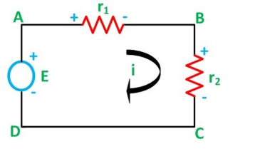
Let us consider a voltage source E with the resistance r1 and r2 connected in series across it. As we know, I = V/R or we can say I = E/R Therefore, the current (i) in the loop ABCD will be: i = E / r1 + r2 -------------------------(8) and r1 = ir1 By putting the value of I from equation (8) in equation (9) the voltage across the resistance r1 and r2 respectively are given by the equation shown below as: E1 = Er1/r1 + r2 and E2 = E r2/ r1 + r2 Thus, the voltage across a resistor in a series circuit is equal to the value of that resistor times the total impressed voltage across the series elements divided by the total resistance of the series elements. |
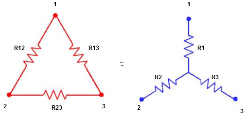
Q4) Explain star to delta conversion?
We know that (from delta to star conversion) R1 =
R2 =
R1 =
Multiply ① X ② L.H.S and R.H.S
R1 R2 =
Similarly, multiply ② X ③
R2 R3 =
And ③ X①
R1 R3 =
Now add equation ④, ⑤, and ⑥ L.H.S and R.H.S
(Delta) Similarly, R23 = R2+R3 +
R23 = R1+R2 +
|
Q5) Explain delta to star conversion? A5) Delta to Star Conversion to Find (Req.)
Delta = R12// (R23 + R13) =R1 + R2
=
= Here let R = R12 + R23 + R13
=
Now the 3 equations after equating L.H.S. and R.H.S R1 + R2 =
R2 + R3 =
R1 + R3 =
Now subtract ② and ① on L.H.S. and R.H.S
R2+ R3 – R1 – R2 =
Now add equation ④ and ③
R3 – R1 + R1 + R3 =
2R3 =
Similarly, R1 =
And R2 = R23 R12/R where R = R12 + R23 + R13 i.e. star equivalent from delta network is the ratio of the product of adjacent branches in the delta to the addition of all branches in the delta.
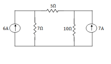
Q6) Using nodal analysis find voltage across 5 resistor.
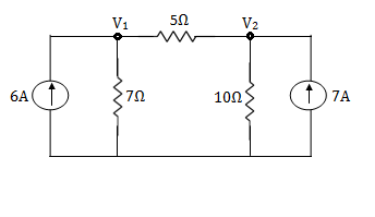
A6)
For V1 For V2
Solving 1 and 2:
For 5 voltage = = -50.9 + 57.27 = 6.37V
Q7) Explain mesh current analysis?
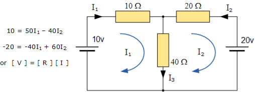
A7) An easier method of solving the above circuit is by using Mesh Current Analysis or Loop Analysis which is also sometimes called Maxwell´s Circulating Currents method. Instead of labelling the branch currents we need to label each “closed loop” with a circulating current. Any required branch current may be found from the appropriate loop or mesh currents as before using Kirchhoff´s method. For example: : i1 = I1 , i2 = -I2 and I3 = I1 – I2 Therefore,
These equations can be solved quite quickly by using a single mesh impedance matrix Z. Each element ON the principal diagonal will be “positive” and is the total impedance of each mesh. Where as, each element OFF the principal diagonal will either be “zero” or “negative” and represents the circuit element connecting all the appropriate meshes. [ V] = [I] x [R] or [R] x [I] = [V]
I = V/R = R-1 x V Inverse of R = [ 60 40 40 50 ] |R| = (60 x 50 ) – (40 x 40 ) = 1400 R – 1 = 1/1400 [ 60 40 40 50] having found the inverse of R, as V/R is the same as V x R-1, we can now use it to find the two circulating currents. [I] = [ R -1] x [V] [ I1]= 1/1400 [ 60 40 [10] [I2 ] = 40 50 ] x [ -20]
I1 = (60 x 10 ) + (40 x -20 ) /1400 = -200/1400 = -0.143 A I2 = (40 x 10 ) + (50 x -20) /1400 = -600/1400 = -0.429A
Where:
and this gives I1 as -0.143 Amps and I2 as -0.429 Amps As : I3 = I1 – I2 The combined current of I3 is therefore given as : -0.143 – (-0.429) = 0.286 Amps
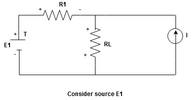
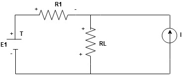
Q8) Explain superposition theorem? A8) Statement: The response in any element of the linear bilateral network containing more than one source is the sum of the responses produced by the individual source acting alone. The responses mean the voltage across the element or the current in the element The voltage sources should be replaced by a short circuit and the current source must be replaced by an open circuit. Steps to apply superposition theorem : 1.
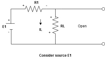
Current sources should be open
Find the current (IL1)(+) through or the voltage across the required element due to the source under consideration using a suitable n/w technique.
Find the current (ILII)(+) by a suitable network simplification technique
2. Add the individual current IL and ILII by the individual sources acting alone to find the total current flowing in load resistance (RL) ie
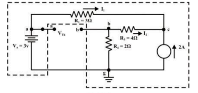
Q9)For the circuit as shown in figure find the current through RL = R2 = 1Ω resistor (Ia-b) branch using Thevenin’s theorem. Find the voltage across the current source.
A9) Step 1: Disconnect the load resistance and reconnect the circuit. Step 2: Apply any method to calculate Vth At node C 2 + I1 + I2 =0 2 + (3 -Vc)/3 + (0-Vc/6) -- Vc = 6V The currents I1 and I2 are computed by the following expressions: I1 = Va -Vc/3 = 3-6/3 = -1A (I1 is flowing from c to a) I2 = 0 – Vc/6 = -6/6 = -1A (I2 is flowing from c to a)
Step-3: Redraw the circuit indicating the direction of currents in different branches. One can find the Thevenin’s voltage VTh using KVL around the closed path ‘gabg’
VTh = Vag − Vbg = 3 − 2 =1volt
Step 4: Replace all sources by their internal resistances. In this problem, voltage source has an internal resistance zero (0) (ideal voltage source) and it is short-circuited with a wire. On the other hand, the current source has an infinite internal resistance (ideal current source) and it is open-circuited (just remove the current source). Thevenin’s resistance RTh of the fixed part of the circuit can be computed by looking at the load terminals ‘a’- ‘b’
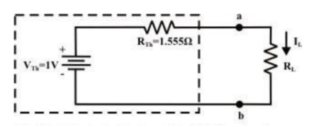
RTh = ( R1 + R3 ) & R4 = ( 3 + 4 )&2 = 1.555Ω Step-5: Place RTh in series with VTh to form the Thevenin’s equivalent circuit. Reconnect the original load resistance RL = R2 = 1 Ω to the Thevenin’s equivalent circuit .
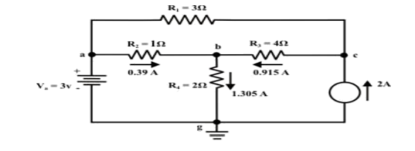
Step-6: The circuit is redrawn to indicate different branch currents. Referring to one can calculate the voltage Vbg and voltage across the current source (Vcg ) using the following equations.
Vbg = Vag − Vab = 3 − 1 × 0.39 =2.61 volt. Ibg = 2.61 2 = 1.305 A; Icb = 1.305 − 0.39 = 0.915 A Vcg = 4 × 0.915 + 2 ×1.305 =6.27 volt. Q10) Find RN, IN, the current flowing through and load Voltage across the load resistor in fig (1) by using Norton’s Theorem.
Step 1: Short the 1.5 Ω load resistor. Step 2: Norton current. Short AB terminals to obtain IN . The total resistance of the circuit is 2Ω + (6Ω || 3Ω) RT = 4 Ω IT = V / RT = 12/ 4 = 3 A IN = 3 A x [ 6Ω / 3 + 6 )] = 2A IN = 2A Step 3: Open current sources, Short Voltage sources and Open Load resistor.
Step 4: Calculate Norton Resistance (RN) Reduce 12V dc source. 3Ω resistor is in series with combination of 6Ω and 2Ω resistor 3Ω + (6Ω||2Ω) 3Ω + 1.5 Ω = 4.5 Ω; RN = 4.5 Ω Step 5: Connect RN in parallel with current source IN and the load resistor.
Step 6: The load current through Load resistor IL = IN x [ RN /(RN + RL) =2 A x ( 4.5 / 4.5 + 1.5 K) = 1.5 A IL = 1.5 A The voltage across load resistor VL = IL x RL = 1.5 x 1.5 VL = 2.25 V
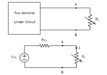
Q11) Explain Maximum Power transfer theorem? A11) Maximum power transfer theorem states that AC voltage source will deliver maximum power to the variable complex load only when the load impedance is equal to the complex conjugate of source impedance. Proof: Replace any two terminal linear network or circuit to the left side of variable load resistor having resistance of RL ohms with a Thevenin’s equivalent circuit. We know that Thevenin’s equivalent circuit resembles a practical voltage source.
The amount of power dissipated across the load resistor is PL = I 2 R L ----------------------(1) Substitute I = Vth / Rth + RL PL = Vth / (Rth + RL ) 2 RL PL = Vth 2 { RL / (RTH + RL) 2 ------------------------------(2) Condition for Maximum Power Transfer For maximum or minimum, first derivative will be zero. So, differentiate Equation 1 with respect to RL and make it equal to zero. dPL / d RL = V Th 2 { (Rth + RL) 2 x 1 -RL x 2(Rth + RL) / (Rth + RL) 4 } =0 (Rth + RL) 2 – 2RL (Rth + RL) = 0 (Rth + RL) (Rth + RL – 2 RL) = 0 Rth - RL = 0 Rth = RL or RL = Rth Therefore, the condition for maximum power dissipation across the load is RL=RTh. That means, if the value of load resistance is equal to the value of source resistance that is Thevenin’s resistance, then the power dissipated across the load will be of maximum value. Substitute RL = Rth and PL = PL,max PL,max = V th 2 { Rth / (Rth + Rth ) 2 } = V th 2 ( Rth / 4 Rth 2 ) = V th 2 / 4 Rth PL,max = V th 2 / 4 RL [RL = Rth]
Efficiency of Maximum power transfer
PL,max = maximum amount of power transferred to the load Ps = amount of power generated by the source. The amount of power generated by the source is Ps = I2 Rth + I2 RL Ps = 2 I2 Rth ; since RL = Rth Substitute I = Vth / 2 Rth Ps = 2(Vth / 2Rth) 2 Rth Ps = 2(Vth / 4Rth) 2 Rth Ps = Vth 2 / 2 Rth Substituting with PL max and Ps
|
