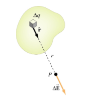
Q1) Derive expression for electric field and electrostatic potential for a continuous charge distribution A1) If the charge distribution is continuous, the potential at a point P can be found by summing over the contributions from individual differential elements of charge. dq
Figure: Continuous charge distribution Consider the charge distribution shown in Figure. Taking infinity as our reference point with zero potential, the electric potential at P due to dq is
Summing over contributions from all differential elements, we have
We established the relation between dV = - In Cartesian coordinates, E = Ex and dV = ( Ex dV = ( Ex dx+ Eydy + Ezdz This implies Ex = By introducing a differential quantity called the “del (gradient) operator”
The electric field can be written as
Notice that ∇ operates on a scalar quantity (electric potential) and results in a vector quantity (electric field). Mathematically, we can think of In the case of gravity, if the gravitational potential increases when a mass is lifted a distance h, the gravitational force must be downward. If the charge distribution possesses spherical symmetry, then the resulting electric field is a function of the radial distance r, i.e. In this case, .dV=- Er dr. If V(r) is known, then
For example, the electric potential due to a point charge q is V = Using the above formula, the electric field is simply E =
|
Q2) Write down Laplace’s and Poisson’s equations for electrostatic potential? A2) A useful approach to the calculation of electric potentials is to relate that potential to the charge density which gives rise to it. The electric field is related to the charge density by the divergence relationship
E = Electric field
and the electric field is related to the electric potential by a gradient relationship E = Therefore the potential is related to the charge density by Poisson's equation
In a charge-free region of space, this becomes Laplace's equation
This mathematical operation, the divergence of the gradient of a function, is called the Laplacian. Expressing the Laplacian in different coordinate systems to take advantage of the symmetry of a charge distribution helps in the solution for the electric potential V. For example, if the charge distribution has spherical symmetry, you use the Laplacian in spherical polar coordinates. Since the potential is a scalar function, this approach has advantages over trying to calculate the electric field directly. Once the potential has been calculated, the electric field can be computed by taking the gradient of the potential. |
Q3) Write a note on divergence of electrostatic field? What is its Physical Interpretation? A3) The electric field can be graphically represented using field lines. The direction of the field lines indicates the direction in which a positive test charge moves when placed in this field. The density of field lines per unit area is proportional to the strength of the electric field. Field lines originate on positive charges and terminate on negative charges. Field lines can never cross since if this would occur, the direction of the electric field at that particular point would be undefined. Examples of field lines produced by positive point charges are shown in Figure
Figure: a) Electric field lines generated by a positive point charge with charge q. b) Electric field lines generated by a positive point charge with charge 2q. The flux of electric field lines through any surface is proportional to the number of field lines passing through that surface. Consider for example a point charge q located at the origin. The electric flux
Since the number of field lines generated by the charge q depends only on the magnitude of the charge, any arbitrarily shaped surface that encloses q will intercept the same number of field lines. Therefore the electric flux through any surface that encloses the charge q is equal to q/
We thus conclude that for an arbitrary surface and arbitrary charge distribution
where Qenclosed is the total charge enclosed by the surface. This is called Gauss's law. Since this equation involves an integral it is also called Gauss's law in integral form. Using the divergence theorem the electric flux
We can also rewrite the enclosed charge Qencl in terms of the charge density ρ
Gauss's law can thus be rewritten as
Since we have not made any assumptions about the integration volume this equation must hold for any volume. This requires that the integrands are equal:
This equation is called Gauss's law in differential form. This is the required expression for divergence of electric field. Divergence is the outflow of flux from a small closed surface area (per unit volume) as volume shrinks to zero.
Physical Interpretation of the Divergence For an electric field:∇·E= ρ/ε, that is there are sources of electric field. Consider a vector field F that represents a fluid velocity: The divergence of F at a point in a fluid is a measure of the rate at which the fluid is flowing away from or towards that point. A positive divergence is indicating a flow away from the point. ƒPhysically divergence means that either the fluid is expanding or that fluid is being supplied by a source external to the field. ƒThe lines of flow diverge from a source and converge to a sink. If there is no gain or loss of fluid anywhere then div F= 0. Such a vector field is said to be solenoidal. Air leaving a punctured tire: Divergence is positive, as closed surface (tire) exhibits net outflow. |
Q4) Write a note on curl of electrostatic field? What is its Physical Interpretation? A4) For a point charge q placing at the origin, the electric field is: E = The curl calculation by integration:
By superposition rule:
The curl calculation by differentiation:
Physical Interpretation of the Curl Consider a vector field F that represents a fluid velocity: The curl of F at a point in a fluid is a measure of the rotation of the fluid. If there is no rotation of fluid anywhere then ∇x F= 0. Such a vector field is said to be irrotational or conservative. An electrostatic field (denoted by E) has the property ∇xE= 0, an irrotational (conservative) field. |
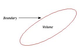
Q5) Discuss Uniqueness Theorems? A5) Consider a volume (see Figure 3.2) within which the charge density is equal to zero. Suppose that the value of the electrostatic potential is specified at every point on the surface of this volume. The first uniqueness theorem states that in this case the solution of Laplace's equation is uniquely defined.
Figure: First Uniqueness Theorem
To proof the first uniqueness theorem we will consider what happens when there are two solutions V1 and V2 of Laplace's equation in the volume shown in Figure. Since V1 and V2 are solutions of Laplace's equation we know that
Since both V1 and V2 are solutions, they must have the same value on the boundary. Thus V1 = V2 on the boundary of the volume. Now consider a third function V3, which is the difference between V1 and V2
The function V3 is also a solution of Laplace's equation. This can be demonstrated easily:
The value of the function V3 is equal to zero on the boundary of the volume since V1 = V2 there. However, property 2 of any solution of Laplace's equation states that it can have no local maxima or minima and that the extreme values of the solution must occur at the boundaries. Since V3 is a solution of Laplace's equation and its value is zero everywhere on the boundary of the volume, the maximum and minimum value of V3 must be equal to zero. Therefore, V3 must be equal to zero everywhere. This immediately implies that V1 = V2 This proves that there can be no two different functions V1 and V2 that are solutions of Laplace's equation and satisfy the same boundary conditions. Therefore, the solution of Laplace's equation is uniquely determined if its value is a specified function on all boundaries of the region. This also indicates that it does not matter how you come by your solution: if (a) it is a solution of Laplace's equation, and (b) it has the correct value on the boundaries, then it is the right and only solution.
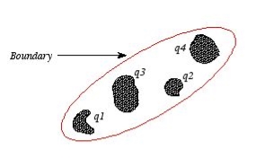
Figure The first uniqueness theorem can only be applied in those regions that are free of charge and surrounded by a boundary with a known potential (not necessarily constant). In the laboratory the boundaries are usually conductors connected to batteries to keep them at a fixed potential. In many other electrostatic problems we do not know the potential at the boundaries of the system. Instead we might know the total charge on the various conductors that make up the system (note: knowing the total charge on a conductor does not imply a knowledge of the charge distribution ρ since it is influenced by the presence of the other conductors). In addition to the conductors that make up the system, there might be a charge distribution ρ filling the regions between the conductors. For this type of system the first uniqueness theorem does not apply. The second uniqueness theorem states that the electric field is uniquely determined if the total charge on each conductor is given and the charge distribution in the regions between the conductors is known. The proof of the second uniqueness theorem is similar to the proof of the first uniqueness theorem. Suppose that there are two fields
where ρ is the charge density at the point where the electric field is evaluated. The surface integrals of
The difference between
satisfies the following equations:
Consider the surface integral of Therefore, The surface integral of
Since the surface integral of the surface integral of
The surface integral
0 = = -
where the volume integration is over all space between the conductors and the outer surface. Since |
A6)Electric potential is work done on a unit charge when bringing from infinity to a point. Whereas potential difference is the difference in electrical potential between two points.
Q7) Derive Bio-Savart law? A7) The Biot Savart Law is an equation describing the magnetic field generated by a constant electric current. It relates the magnetic field to the magnitude, direction, length, and proximity of the electric current. Biot–Savart law is consistent with both Ampere’s circuital law and Gauss’s theorem. The Biot-Savart law is fundamental to magnetostatics, playing a role similar to that of Coulomb’s law in electrostatics. The Biot-Savart law can be stated as:
Where, k is a constant, depending upon the magnetic properties of the medium and system of the units employed. In the SI system of unit,
Therefore, the final Biot-Savart law derivation is,
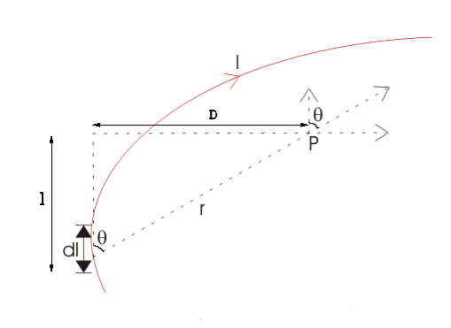
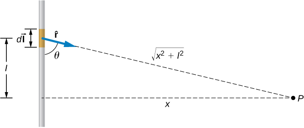
DERIVATION Let us consider a long wire carrying a current I and also consider a point p in the space. The wire is presented in the picture below, by red colour. Let us also consider an infinitely small length of the wire dl at a distance r from the point P as shown. Here, r is a distance-vector which makes an angle θ with the direction of current in the infinitesimal portion of the wire. If you try to visualize the condition, you can easily understand the magnetic field density at point P due to that infinitesimal length dl of the wire is directly proportional to current carried by this portion of the wire. As the current through that infinitesimal length of wire is the same as the current carried by the whole wire itself, we can write,
The magnetic field density at that point P due to that infinitesimal length dl of wire is inversely proportional to the square of the straight distance from point P to the center of dl. Mathematically we can write this as,
FIGURE 1
As θ be the angle between distance vector r and direction of current through this infinitesimal portion of the wire, the component of dl directly facing perpendicular to the point P is dlsinθ,
Now, combining these three statements, we can write,
This is the basic form of Biot Savart’ s Law Now, putting the value of constant k (which we have already introduced at the beginning of this article) in the above expression, we get
Here, μ0 used in the expression of constant k is absolute permeability of air or vacuum and its value is 4π |
Q8) What do you meant by divergence and curl of magnetic field? A8) The static electric field E(x; y; z) such as the field of static charges obeys equations ∇. E =
The static magnetic field B(x; y; z) such as the field of steady currents obeys different equations
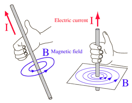
Due to this difference, the magnetic field of long straight wire looks quite different from the electric field of a point charge or a linear charge. Later in these notes we will derive equations (3.2c) and (3.2d) from the Biot Savart Law. Let us explore some of their consequences. The zero-divergence equation (3.2c) is valid for any magnetic field, even if it is time-dependent rather than static. Physically, it means that there are no magnetic charges, otherwise we would have ∇.B Consequently, the magnetic field lines never begin or end anywhere in space; instead they form closed loops or run from in infinity to in infinity. The integral form of eq. (3.2c) follows by the Gauss theorem: the magnetic flux through any closed surface is zero
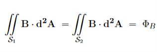
Consequently, any open surfaces S1,S2,……..spanning the same loop L have the same magnetic flux through them, for example
Figure 4
We shall this identity very useful for stating the Faraday's Law of magnetic induction. Now consider the curl equation
which is the differential form of the Ampere's Law. The integral form of the Ampere's Law obtains by the Stokes' theorem: For any closed loop L and any surface S spanning that loop,
………..(3.2e)
Where Inet [through L] is the net electric current flowing through the loop L. The integral form (3.2e) of the Ampere's Law is particularly convenient when the current flows through a wire or several wires; in this case all we need is to check which wire goes through the loop L and which does not, then add up the currents in the wires that do go through L and mind their directions. But it is also convenient for the volume currents flowing through thick conductors or for current sheets flowing on surfaces. As we know that the Ampere's Law applies only to the magnetic fields of steady currents. Otherwise, we need to use the more general Maxwell {Ampere Law, with an extra term for the time-dependent electric field. For simplicity we say that the original Ampere's Law is simply mathematically inconsistent unless the electric current has zero divergence,∇J= 0.Indeed, the left hand side of the curl equation ∇. ( So we cannot have ( ∇.J= 0. As to the integral form (3.2e) of the Ampere's Law, we need a divergence-less current density J to make sure that the net current through the loop L is the same for any surface S spanning the loop; otherwise we simply cannot de ne the net current through L |
Q9) Determining whether a field F(x,y) = x2y, y-xy2 is Magnetic? A9) it is possible for F(x,y) = x2y, y-xy2 to be a magnetic field, if its divergence would be zero. If F were magnetic, then its divergence would be zero. The divergence of F is
and therefore F cannot model a magnetic field The divergence of vector field F(x,y) = x2y, y-xy2 is one, so it cannot model a magnetic field. |
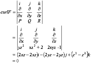
Q10) Determine if the vector field F = yz2i + (xz2 + 2) j + (2xyz - 1) k is conservative. |
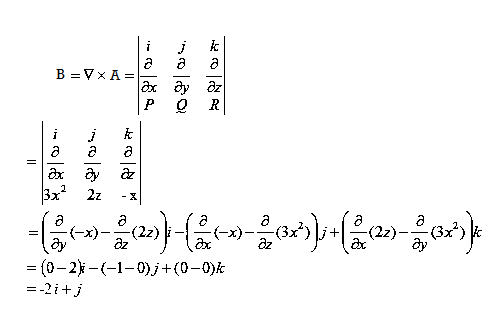
Q11) Find the magnetic field where vector potential associated with field is given by A(x, y, z) = 3x2i + 2zj – xk. A11)
|
Q12) Find the magnetic field where vector potential associated with field is given by A= (x + y + z, x − y – z, x2 + y2 + z2)?
|
Q13) Derive equation of divergence and curl of magnetic field? A13) In general, when dealing with a current density J(x’) instead of a current I so (equation 1 of article 3.1) for the magnetic induction B(x) takes the form
Equation (1) can be expressed differently, since
but since
We get
If we set
Equation (5) is a mathematical statement on the inexistence of magnetic monopoles. Taking the curl of the B field, Using this identity
……….(5)
Solving this we get
This equation can be further simplified by using the divergence theorem
Since
If we evaluate the integral on both sides of equation (7) over an open surface S of contour C (see Figure ), we find
Figure: A magnetic induction is induced around a circuit C by a current density J through the open surface S bounded by C. and using Stokes’ theorem
c where I is the current passing through the surface. Equations (8) and (9) are mathematical representations of Ampère’s Law. |
Q14) Derive Ampere’s Law from biot savrat law? A14)
FIGURE 1 Biot-Savrat law is given by
Here, μ0 used in the expression of constant k is absolute permeability of air or vacuum and its value is 4π Now, flux density (B) at the point P due to the total length of the current-carrying conductor or wire can be represented as,
If D is the perpendicular distance of the point P from the wire, then
Now, the expression of flux density B at point P can be rewritten as,
As per the figure above,
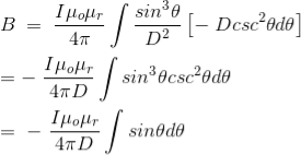
Finally, the expression of B comes as,
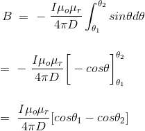
This angle θ depends upon the length of the wire and the position of the point P. Say for a certain limited length of the wire, angle θ as indicated in the figure above varies from θ1 to θ2. Hence, magnetic flux density at point P due to the total length of the conductor is,
Let’s imagine the wire is infinitely long, then θ will vary from 0 to π that is θ1 = 0 to θ2 = π. Putting these two values in the above final expression of Biot Savart law, we get,
This is nothing but the expression of Ampere’s Law. |
Q15) A short wire of length 1.0 cm carries a current of 2.0 A in the vertical direction (as shown in figure). The rest of the wire is shielded so it does not add to the magnetic field produced by the wire. Calculate the magnetic field at point P, which is 1 meter from the wire in the x-direction.
Solution: The angle between Δl⃗ and θ=tan−1(1m/0.01m)=89.4o. The magnetic field at point P is calculated by the Biot-Savart law
|
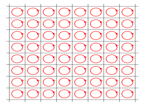
Q16) What is the Origin of the Bound Currents? Discuss in brief. A16) Physically, the bound currents on the surface of a magnetized material (and also in its volume for a non-uniform M) originate from the mis-cancellation of the microscopic currents inside the atoms which give rise to their magnetic moments. As a model of how this works, consider a large L m=a3M …………(1) The picture below shows a single slice of this cubic lattice along the (x; y) plane, or rather a small part of that slice:
Figure 1 The red loops here stand for the current loops creating the atomic magnetic moments m. We do not know the radii or even the shapes of these loops or the currents which flow through them; we do not even know if the currents are line currents or volume currents. But for our purposes all such details do not matter, all we care is the net magnetic moment m of each atom. As far as the macroscopic magnetic field B(r) is concerned, we may replace each atom with an a I = flowing around the 4 vertical sides of the cube. Here is the picture of such a cubic model, or rather, of a small part of a single slice of the cubic lattice:
Figure 2
Inside each atom, the current flows counter clockwise. But when we look at the boundary between two neighbouring atoms, we immediately see that over that boundary, the currents of the two atoms flow in opposite directions. And since they have the same magnitude I=m/a2, they cancel each other. Thus, in the middle of the crystal all the atomic currents cancel each other and there is no net current. However, at the outer boundary of the crystal there is no cancellation.
Figure 3 Instead, there is un-cancelled current I=m/a2 flowing counter clockwise around the entire outer boundary of the crystal, or rather of single atomic layer of the crystal. The next layer on top of the layer shown on the above picture has a similar current, and so is every other layer, which makes for a surface current density. K = Over the 4 vertical sides of the whole magnetized cube. In vector notations, the surface current on each side of the cube is K = M where n is the unit vector normal to the side in question. The above toy model explains the physical origin of the surface bound current. It does not have a volume bound current since we assumed a uniform magnetization inside the magnetic material. To model a non-uniform magnetization we should give different atoms different magnetic moments m and hence different atomic currents. Consequently, at the boundary of two neighbouring atoms we would no longer have exact cancellation of their currents, and that would give rise to bound volume currents inside the bulk of the magnetized material. Assuming for simplicity that all atomic magnetic moments point in z directions but their magnitudes slowly depend on x and y coordinated of the atom, the net current on the boundary between two atoms neighbouring in x direction is
while on the boundary between two atoms neighbouring in y direction
Averaging these currents over the volume of the magnetized crystal, we get the volume bound current
…………(7) |
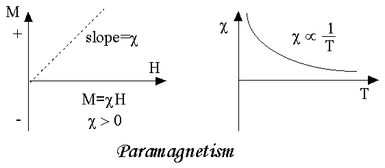
 χ = 0 in vacuumχ = +ve for paramagnetic and Ferro magnetic materialsχ = -ve for diamagnetic materials Units: It has no units.
Q18) The magnetic susceptibility of silicon is −0.4 × 10⁻⁵. Calculate the flux density and magnetic moment per unit volume when magnetic field of intensity 5 × 10⁵ A/m is applied. A18) Given: χ = –0.4 × 10‒5 H = 5 × 10⁵ A /m B = ? and M = ? B = μ0(H + M) = μ0 H(1 + χ) = 4π × 10‒7 × 5 × 105 [1 – 0.4 × 10‒5] = 4π × 5 × 10‒2 × 0.9996 = 0.62 Wb/m2 M = χH = –0.4 × 10–5 × 5 × 105 = –2.0 A/m. |
Figure 6 |
Figure 7 |
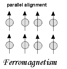 The elements Fe, Ni, and Co and many of their alloys are typical ferromagnetic materials. Two distinct characteristics of ferromagnetic materials are their (1) Spontaneous magnetization and(2) Magnetic ordering temperature Figure 8 Spontaneous MagnetizationThe spontaneous magnetization is the net magnetization that exists inside a uniformly magnetized microscopic volume in the absence of a field. The
 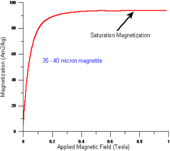 magnitude of this magnetization, at 0 K, is dependent on the spin magnetic moments of electrons.A related term is the saturation magnetization which we can measure in the laboratory. The saturation magnetization is the maximum induced magnetic moment that can be obtained in a magnetic field (Hsat); beyond this field no further increase in magnetization occurs. The difference between spontaneousFigure 9 magnetization and the saturation magnetization has to do with magnetic domains (more about domains later). Saturation magnetization is an intrinsic property, independent of particle size but dependent on temperature.There is a big difference between paramagnetic and ferromagnetic susceptibility. As compared to paramagnetic materials, the magnetization in ferromagnetic materials is saturated in moderate magnetic fields and at high (room-temperature) temperatures:
| Hsat Tesla | T range (K) | χ 10-8m3/kg |
paramagnets | >10 | <<100 | ~50 |
ferromagnets | ~1 | ~300 | 1000-10000 |
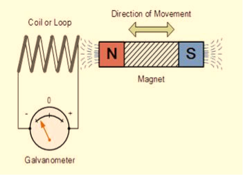
Figure 1 |
Position of magnet | Deflection in galvanometer |
Magnet at rest | No deflection in the galvanometer |
Magnet moves towards the coil | Deflection in galvanometer in one direction |
Magnet is held stationary at same position (near the coil) | No deflection in the galvanometer |
Magnet moves away from the coil | Deflection in galvanometer but in the opposite direction |
Magnet is held stationary at the same position (away from the coil) | No deflection in the galvanometer |
Method to change the magnetic field:
Faraday Law Formula Consider, a magnet is approaching towards a coil. Here we consider two instants at time T1 and time T2. Coil has N number of turns. Flux linkage with the coil at time,
Flux linkage with the coil at time,
Change in flux linkage,
Let this change in flux linkage be,
So, the Change in flux linkage
Now the rate of change of flux linkage
Take derivative on right-hand side we will get as N is number of turns of coils which is constant so taken out of derivative, we get
The rate of change of flux linkage
Where E is induced emf. But according to Faraday’s law of electromagnetic induction, the rate of change of flux linkage is equal to induced emf.
|
Figure 5 |
Figure 6 |
Figure 7 |
Figure 8
|
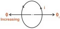
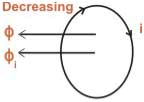 Figure 9 LENZ’S LAW FORMULALenz’s law states that when an EMF is generated by a change in magnetic flux according to Faraday’s Law, the polarity of the induced EMF is such, that it produces an induced current whose magnetic field opposes the initial changing magnetic field which produced itThe negative sign used in Faraday’s law of electromagnetic induction, indicates that the induced EMF (ε) and the change in magnetic flux (δΦB) have opposite signs. The formula for Lenz’s law is shown below
 Where:
Q29) Derive Maxwell’s equations in vacuum and in non-conducting medium? Solution: Maxwell’s four equations are given by ∇·E = ρ/ε0 (1) ∇×E = −∂B/∂t (2) ∇×H = J + ∂D/∂t (3) ∇·B = 0 (4) These equations illustrate the unique coexistence in nature of the electric field and the magnetic field. The first two equations give the value of the given flux through a closed surface, and the second two equations give the value of a line integral around a loop. In this notation, ∇=(∂/∂x, ∂/∂y, ∂/∂z) E is the electric vector B is the magnetic induction ρ is the electric charge density j is the electric current density ε0 is the permittivity of free space c is the speed of light.
In addition to Maxwell equations, the following identities are useful:
J = σE (5) D = εE (6) B = μH (7)
Here, D is the electric displacement H is the magnetic vector σ is the specific conductivity ε is the dielectric constant (or permittivity) μ is the magnetic permeability Free space or non-conducting medium. We know that non conducting medium means no current so conductivity is zero i.e. σ=0 So current density J=σE will also become zero as σ=0 Also free space means no charges which leads to ρ=0. These points mentioned below. (a) No condition current i.e σ=0, thus J=0 ( J=σE) (b) No charges (i.e ρ=0) For the case of no charges or currents, that is, j = 0 and ρ = 0, and a homogeneous medium. Using these the Maxwell equation can rewritten as ∇.D=0 or ∇.E=0 as ρ=0 (12) ∇ x E= -dB/dt or ∇ x E= -μ dH/dt because B = μH (13) ∇ x H=d D/dt or ∇ x H = ε dE/dt (J=0) and D = εE (14) ∇.B=0 (15) Now taking curl of second Maxwell’s equation (13) ,we get ∇ x(∇ x E)=- μ d/dt (∇ x H) Applying standard vector identity, that is [∇ *(∇*E)=∇(∇.E)-∇2E] on left hand side of above equation, we get ∇ (∇ .E)-∇2E= -μ d/dt (∇ x H) (16) Substituting equations (13) and (14) in equations (16) ,we get -∇2E= – με d/dt (dE/dt) Or ∇2E=με d 2 E/dT2 (17) Equation (17) is the required wave equation in terms of electric field intensity, E for free space . This is the law that E must obey. Wave Equation In Terms Of Magnetic Field Intensity, H Take curl of fourth Maxwell’s equation(14) ,we get ∇x(∇xH)=ε d/dt(∇xE) Applying standard vector identity that is [∇*(∇*H)=∇ (∇.H)-∇2H] On left side of above equation , we get ∇(∇.H)-∇2H= ε d/dt(∇xE) (18) Substituting equations (14) and (13) in equation(18) ,we get -∇2H= – μεd/dt(dH/dt) Or ∇2H=με d2H/dt2 (19) Equations (19) is the required wave equation in terms of magnetic field intensity, H and this is the law that H must obey For vacuum μ=μ0 and ε=ε0, equations (17) and (19) will become ∇2 E=μ0ε0 d2E/dt2 (20) And ∇2H= μ0ε0 d2H/dt2 (21)
This leads to an expression for the velocity of propagation From equation both equations (20) and (21) have the form of the general wave equation for a wave
(x,t) traveling in the x direction with speed v. Equating the speed with the coefficients, we derive the speed of electric and magnetic waves, which is a constant that we symbolize with “c” It is useful to note that in vacuum c2=1/ε0μ0 Where μ0 is the permeability of free space
|
Q30) Given E = 10 sin (t-y) ay V/m, in free space, determine D, B and H. A30) E = 10 sin (t-y) ay, V/m D =0E, 0= 8.854 x 10⁻¹² F/m D = 100sin (t-y) ay, C/m2 Second Maxwell’s equation is x E = -B That is,
or
As Ey= 10 sin (t-z) V/m
Now,x E becomes x E = - = 10 cos (t-z) ax = -
|
 The displacement along x-axis after time “t” is given by : x=v0t+
 ayt2x=v0t+
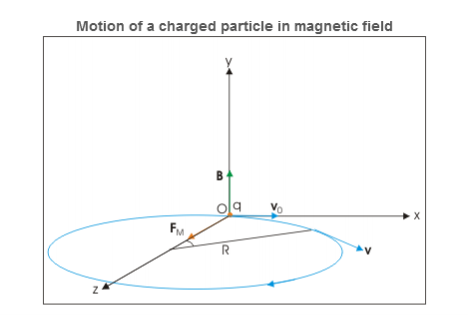
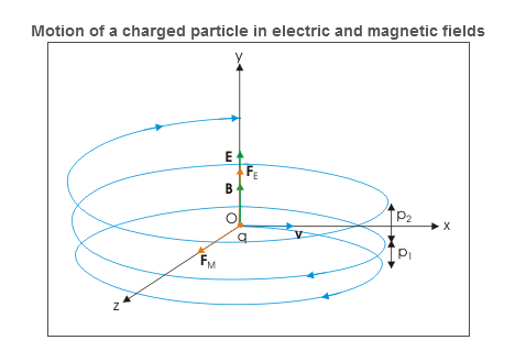
 t2Charge is moving perpendicular to parallel electric and magnetic fields Let electric and magnetic fields align along y-direction and velocity vector is aligned along positive x-direction. Let the charge be positive and initial velocity be v0.In this case, velocity and magnetic field vectors are perpendicular to each other. Applying Right hand vector cross product rule, we determine that magnetic force is acting in positive z-direction. If electric field is not present, then the particle revolves along a circle in xz plane as shown in the figure below.
Figure 23 |
Figure 24 |
 T =
T =  ν=
ν=  ω=αB Velocity of the charged particle The velocity of the particle in xz is: v=vxi + vzj=v0cosωt i+ vosinωt k⇒v= v0cosωt i+ vosinωt k= v0cos(αBt)i+v0sin(αBt)kwhere α is specific charge. We know that magnetic force does not change the magnitude of velocity. It follows then that magnitude of velocity is xy plane is a constant given as: v2x+v2z=vxy2But, there is electric field in y-direction. This imparts linear acceleration to the charged particle. As such, the particle which was initially having no component in y direction gains velocity with time as electric field imparts acceleration to the particle in y direction. The velocity components in xz plane, however, remain same. The acceleration in y-direction due to electric field is: ⇒ay=
  =
=  =αESince initial velocity in y-direction is zero, the velocity after time t is: ⇒vy=ayt=αEtThe velocity of the particle at a time t, therefore, is given in terms of component velocities as : v=vxi+ vyj+ vjk⇒v=v0cos(αBt) i+αEt j+v0sin(αBt) kDisplacement of the charged particle Component of displacement of the charged particle in xz plane is given as
Figure 25 x=R sin(αBt)= z=R[1−cos(αBt)]= The motion in y-direction is due to electric force. Let the displacement in this direction be y after time t. Then: y= The position vector of the particle after time t is : r=xi+yj+zk ⇒r= |
Figure 25 |
Figure 26 |
Figure 28 |
Figure 29 |
Figure 30
|
Figure 31 |
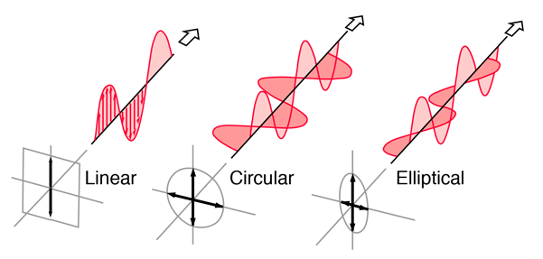
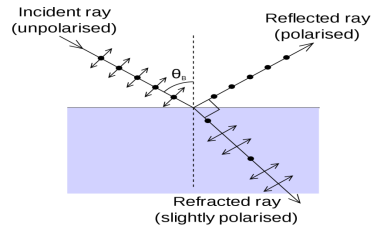
Figure 32: Showing Linear, Circular and Elliptical Polarization |
Figure 33 |
Figure 34 |
Figure 35 |
