Unit 2
AC Circuit
- Explain single phase AC supply ?
In the field of electrical, single phase supply is the delivery of AC power by a system in which all the supply voltages change in simultaneously. This type of power supply sharing is used when the loads (home appliances) ate generally heat and lighting with some huge electric motors. When a single phase supply is connected to an AC motor doesn’t generate a rotating magnetic field, single phase motors require extra circuits for working, but such electric motors are rare over in rating of 10 kW. In every cycle, a single phase system voltage achieves a peak-value two times; the direct power is not stable.
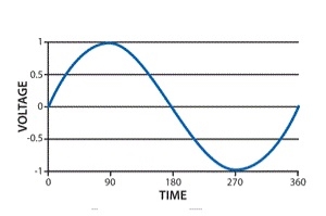 Single Phase Waveform
A load with single-phase can be power-driven from a three-phase sharing transformer in two techniques. One is with the connection between two phases or with connection among one phase and neutral. These two will give dissimilar voltages from a given power supply. This type of phase supply provides up to 230V. The applications of this supply mainly use for running the small home appliances like air conditioners, fans, heater, etc.
Single Phase Supply Benefits
The benefits of choosing a single phase supply include the following.
- The design is less complex
- Design cost is less
- Most efficient AC power supply for up to 1000 watts
- Single Phase AC Power Supply is most competent for up to 1000 watts.
- Wide-range of application uses
Single Phase Supply Applications
The applications of single-phase supply include the following.
- This power supply is applicable for homes as well as businesses.
- Used to supply plenty of power for homes, as well as nonindustrial businesses.
- This power supply is sufficient to run the motors up to about 5 horsepower (hp).
2. Explain pure resistive circuit?
Ac circuit containing pure resisting

Consider Circuit Consisting pure resistance connected across the ac voltage source
V = Vm Sin ωt ①
According to ohm’s law i =  =
= 
But Im = 
 ②
②
Phases diagram
From ① and ② phases or represents RMD value.
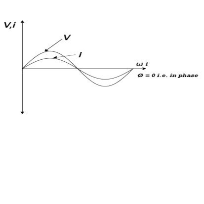
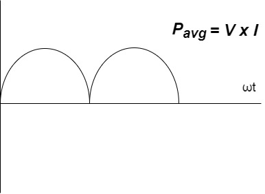
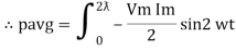
Power P = V. i
Equation P = Vm sin ω t Im sin ω t
P = Vm Im Sin2 ω t
P =  -
- 

Constant fluctuating power if we integrate it becomes zero

Average power
Pavg = 
Pavg = 
Pavg = Vrms Irms
Power ware form [Resultant]
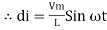
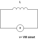
3. Explain pure inductive circuit?
Ac circuit containing pure Inductors

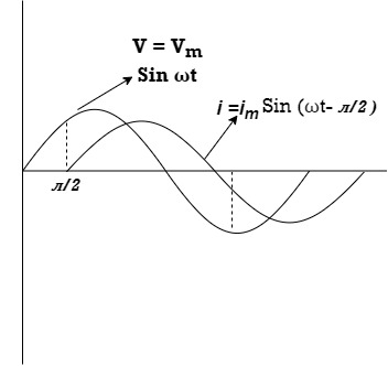
Consider pure Inductor (L) is connected across alternating voltage. Source
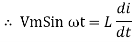
V = Vm Sin ωt
When an alternating current flow through inductance it setups alternating magnetic flux around the inductor.
This changing the flux links the coil and self-induced emf is produced
According to faradays Law of E M I
e = 
At all instant applied voltage V is equal and opposite to self-induced emf [ Lenz's law]
V = -e
 =
= 
But V = Vm Sin ωt
 dt
dt
Taking integrating on both sides
 dt
dt
 dt
dt

 (-cos
(-cos  )
)

But sin (– ) = sin (+
 )
)
 sin (
sin ( -
-  /2)
/2)
And Im= 
 /2)
/2)
 /2
/2
= -ve
= lagging
= I lag v by 900
Waveform:

Phasor:

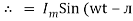
Power P = Ѵ. I
= Vm sin wt Im sin (wt  /2)
/2)
= Vm Im Sin wt Sin (wt –  /s)
/s)
 ①
①
And
Sin (wt -  /s) = - cos wt ②
Sin (wt –  ) = - cos
 sin 2 wt from ① and ②
The average value of sin curve over a complete cycle is always zero
 Pavg = 0
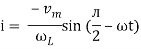
3.Explain pure capacitive circuit?
Ac circuit containing pure capacitors:
Consider pure capacitor C is connected across an alternating voltage source
Ѵ = Ѵm Sin wt
Current is passing through capacitor the instantaneous charge ɡ produced on the plate of the capacitor
ɡ = C Ѵ
ɡ = c Vm sin wt
The current is the rate of flow of charge

i= (cvm sin wt)
i = c Vm w cos wt
Then rearranging the above eqth.
i =  cos wt

 = sin (wt +
  X/2)
X/2)
i =  sin (wt + X/2)
But 
 X/2)
X/2)

= leading
= I leads V by 900
Waveform :
Phase
Power P= Ѵ. i
= [Vm sinwt] [ Im sin (wt + X/2)]
= Vm Im Sin wt Sin (wt + X/2)]
 (cos wt)

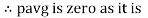 to charging power waveform [resultant].
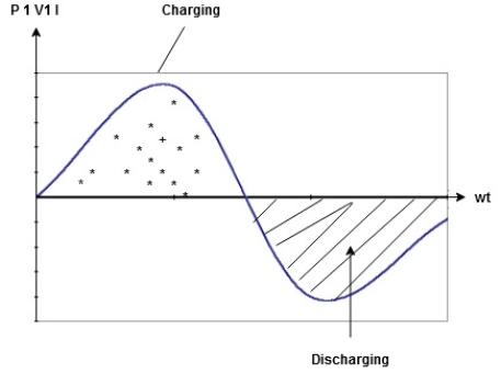
4. Explain series R-L-C circuits?
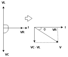
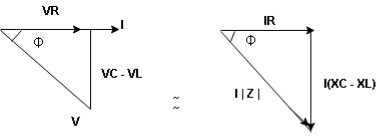
Consider ac voltage source V = Vm sin wt connected across the combination of R L and C. When I flowing in the circuit voltage drops across each component as shown below.
VR = IR, VL = I  L, VC = I
  C
C
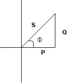
- According to the values of Inductive and Capacitive Reactance, I e XL and XC decides the behavior of R-L-C series circuit according to following conditions
① XL> XC, ② XC> XL, ③ XL = XC
① XL > XC: Since we have assumed XL> XC
 The voltage drop across XL> than XC
 VL> VC A
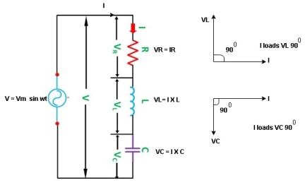
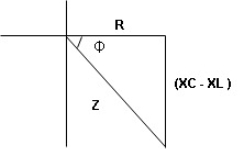
- Voltage triangle considering condition A

VL and VC are 180 0 out of phase.
Therefore cancel out each other
 Resultant voltage triangle
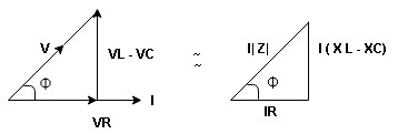
Now V = VR + VL + VC c phasor sum and VL and VC are directly in phase opposition and VL
 VC
VC their resultant is (VL - VC).
From voltage triangle
V = 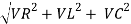
 V =
V = 
 V = I
V = I 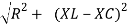

Impendence  : divide voltage
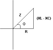
Rectangular form Z = R + j (XL – XC)
Polor form Z =  l + Ø B
Where  =
= 
And Ø = tan-1 
- Voltage equation : V = Vm Sin wt
- Current equation
i =  from B
i =  L-Ø C
L-Ø C
As VL VC the circuit is mostly inductive and
  I lags behind V by angle Ø
 Since i =
  L-Ø
L-Ø
 i = Im Sin (wt – Ø) from c
- XC
 XL :Since we have assured XC
  XL
XL
 the voltage drops across XC
  than XL
 XC
XC  XL (A)
 voltage triangle considering condition (A)
 Resultant Voltage
Now V = VR + VL + VC  phases sum and VL and VC are directly in phase opposition and VC
 VL
VL  their resultant is (VC – VL)
From voltage 
V = 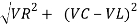
V = 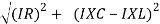
 V =
V = 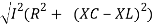
 V =
V = 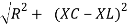

 Impedance
  : Divide voltage
- Rectangular form : Z + R – j (XC – XL) – 4th qurd
Polar form : Z =  L -
L -
Where 
And Ø = tan-1 – 
- Voltage equation : V = Vm Sin wt
- Current equation : i =
 from B
 - i =
 L+Ø C
L+Ø C
As VC  the circuit is mostly capacitive and
  leads voltage by angle Ø
Since i =  L + Ø
L + Ø
 Sin (wt – Ø) from C
- Power
 :
:
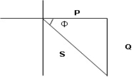
- XL= XC (resonance condition):
ɡȴ XL= XC then VL= VC and they are 1800 out of phase with each other  they will cancel out each other and their resultant will have zero value.
Hence resultant V = VR and it will be in phase with I as shown in the below phasor diagram.
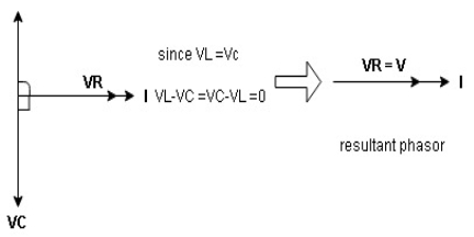
From the above resultant phasor diagram
V =VR + IR
Or V = I  lZl
lZl
Because lZl + R
Thus Impedance Z is purely resistive for XL = XC and circuit current will be in phase with source voltage.

 Since VR=V Øis zero when XL = XC
  power is unity
Ie pang = Vrms I rms cos Ø = 1 cos o = 1
Maximum power will be transferred by the condition. XL = XC
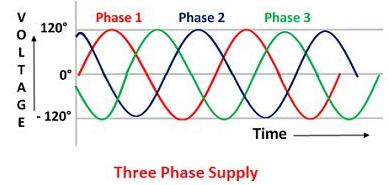
4.Explain three phase supply ?
The three phase system consist four wires, three conductors and one neutral. The conductors are out of phase and space 120º apart from each other. The three phase system is also used as a single phase system. For the low load, one phase and neutral can be taken from the three phase supply.
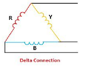
5. Explain the star and delta connections?
The three phase supply is continuous and never completely drops to zero. In three phase system power can be drawn either in a star or delta configuration. The star connection is used for long distance transmission because it has neutral for the fault current.

The delta connection consists three phase wires and no neutral.
6. Explain line and phase values?
The three- phase supply is continuous and never completely drops to zero. In three phase system power can be drawn either in a star or delta configuration. The star connection is used for long distance transmission because it has neutral for the fault current.
The delta connection consists three phase wires and no neutral.
Line and Phase Values:
•The three components comprising a three-phase source or load are called phases.
•Line voltage is the voltage measured between any two lines in a three-phase circuit.
•Phase voltage is the voltage measured across a single component in a three-phase source or load.
•Line current is the current through any one line between a three-phase source and load.
•Phase current is the current through any one component comprising a three-phase source or load.
•In balanced “Y” circuits, the line voltage is equal to phase voltage times the square root of 3, while the line current is equal to phase current.
For Y circuits
E line =  Ephase
I line = I phase
•In balanced Δ circuits, the line voltage is equal to phase voltage, while the line current is equal to phase current times the square root of 3.
For Δ circuits
Eline = Ephase
I line =  E phase
•Δ-connected three-phase voltage sources give greater reliability in the event of winding failure than Y-connected sources. However, Y-connected sources can deliver the same amount of power with less line current than Δ-connected sources.
7. Explain the solution of balanced three phase circuits?
The following steps are given below to solve the balanced three-phase circuits.
Step 1 – First of all draw the circuit diagram.
Step 2 – Determine XLP = XL/phase = 2πfL.
Step 3 – Determine XCP = XC/phase = 1/2πfC.
Step 4 – Determine XP = X/ phase = XL – XC
Step 5 – Determine ZP = Z/phase = √R2P + X2P
Step 6 – Determine cosϕ = RP/ZP; the power factor is lagging when XLP > XCP and it is leading when XCP > XLP.
Step 7 – Determine the V phase.
For star connection VP = VL/√3 and for delta connection VP = VL
Step 8 – Determine IP = VP/ZP.
Step 9 – Now, determine the line current IL.
For star connection IL = IP and for delta connection IL = √3 IP
Step 10 – Determine the Active, Reactive and Apparent power.
8. Explain the phasor diagram?
Phasor Diagram :
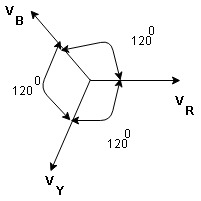
Equation
VR = Vm Sin wt
VY = Vm Sin (wt-1200)
VB = sin (wt – 2400)
Or VB = Vm sin (wt + 1200)
9. Explain the advantages of single phase over three phase?
- More output: for the same size the output of the 3Ø machine is always higher than the single 1 Ø phase machine.
- Smaller size: for producing the same output the size of 3 phase machine is always smaller than of single-phase machine
- 3 phase motor is self-starting as the 3 Ø ac supply is capable of producing a rotating magnetic file when applied are self-starting 1 Ø motor need additional starter winding
- More power is transmitted: in the transmitted system, it is possible to transmit more power using 3 Ø system rather than 1 Ø system, by using conductor of the same cross-sectional.
- The smaller cross-sectional area of conductor
ɡȴ same amount of power is to transmitted than the cross-sectional area of conductor used for 3 Ø system is small as compared to that for single Ø system.
10. Explain the applications of three phase supply?
- Greater power density
- Easier balance loads
- Minimizes harmonic currents
- Optimizes utilization of electrical capacity.


