EG
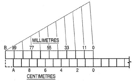
UNIT 1Introduction of Engineering Graphics Q1 Significance of Engineering Graphics.Ans: 1. Ability to read and prepare engineering drawings.2. Ability to make free - hand sketching of objects.3. Power to imagine, analyze and communicate, and4. Capacity to understand other subjects. Q2 What is the use of Tracing paper?Ans:Tracing papers are thin papers, natural or transparent, on which drawings are traced, in pencil or ink, and from which blueprints or similar contact prints can be made. In most drafting rooms original drawings are penciled on tracing papers, and blueprints are made directly from these drawings, a practice increasingly successful because of improvements both in papers and in printing.Q3 What is the use of Thumbtacks?Ans:The best thumbtacks are made with thin heads and steel points screwed into them. Cheaper ones are made by stamping. Use tacks with tapering pins of small diameter and avoid flat-headed (often colored) map pins, as the heads are too thick and the pins rather large.Q4 How T Squares aid drawing?Ans:The fixed-head T square is used for all ordinary work. It should be of hardwood, and the blade should be perfectly straight. The transparent-edged blade is much the best. A draftsman will have several fixed-head squares of different lengths and will find an adjustable-head square of occasional use. Q5 List different types of scales.Ans:Scales, are made in various number of graduations to meet the requirements of many kinds of work. For convenience, scales are classified according to their most-common uses.Mechanical Engineer’s ScaleThese are divided and numbered in such a way that fractions of inches represent inches. The most common ranges are 1/8, 1/4, 1/2, and 1 in. to the inch. These scales are known as the size scales because the reduced size also represents the ratio of size, as for example one-eighth size.Mechanical engineer's scales are almost always "full divided"; that is, the smallest divisions run throughout the entire length.Civil Engineer’s ScaleThese are divided into decimals with divisions ranging from 10, 20, 30, 40, 50, 60, and 80 to the inch. Such a scale is usually full divided and is sometimes numbered both from left to right and right to left. Civil engineer's scales are most used for plotting and drawing maps, although they are convenient for any work where divisions of the inch in tenths is required.Metric ScalesMetric scales are supplied in all the styles and sizes and materials of other scales. They are usually full-divided and are numbered in meters, centimeters, or millimeters depending upon the reduction in size. Typical size reductions are: 1:1, 1:2, 1:5, 1:10, 1:20, 1:25, 1:33.3, 1:50, 1:75, 1:80, 1: 100, 1: 150. Also available are metric equivalent scales for direct conversion of English scales. Q6 What is single stroke lettering?Ans:By far the greatest amount of lettering on drawings is done in a rapid single-stroke letter, either vertical or inclined, and every engineer must have absolute command of these styles.The term "single-stroke," or "one-stroke," does not mean that the entire letter is made without lifting the pencil or pen but that the width of the stroke of the pencil or pen is the width of the stem of the letter. Q7 What is Vernier scale?Ans:Vernier scales, like diagonal scales, are used to read to a small unit with great accuracy. A Vernier scale consists of two parts - a primary scale and a Vernier. The primary scale is a plain scale fully divided into minor divisions. As it would be difficult to sub-divide the minor divisions in the ordinary way, it is done with the help of the Vernier. The graduations on the Vernier are derived from those on the primary scale.(a) Principle of Vernier: Fig. shows a part of a plain scale in which the length AO represents 10 cm. If we divide AO into ten equal parts, each part will represent 1 cm. It would not be easy to divide each of these parts into ten equal divisions to get measurements in millimeters.
Q8 List out steps for drawing ellipse through arc of circle method.Ans:
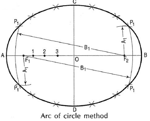
(i) Draw a line AB equal to the major axis and a line CO equal to the minor axis, bisecting each other at right angles at 0.(ii) With centre C and radius equal to half AB (i.e. AO) draw arcs cutting AB at F1 and F2, the foci of the ellipse.(iii) Mark several points 1, 2, 3 etc. on AB.(iv) With centres F1 and F2 and radius equal to A1, draw arcs on both sides of AB.(v) With same centres and radius equal to B1, draw arcs intersecting theprevious arcs at four points marked P1.(vi) Similarly, with radii A2 and B2, A3 and B3 etc. obtain more points.(vii) Draw a smooth curve through these points. This curve is the required ellipse.
 Q5 List different types of scales.Ans:Scales, are made in various number of graduations to meet the requirements of many kinds of work. For convenience, scales are classified according to their most-common uses.Mechanical Engineer’s ScaleThese are divided and numbered in such a way that fractions of inches represent inches. The most common ranges are 1/8, 1/4, 1/2, and 1 in. to the inch. These scales are known as the size scales because the reduced size also represents the ratio of size, as for example one-eighth size.Mechanical engineer's scales are almost always "full divided"; that is, the smallest divisions run throughout the entire length.Civil Engineer’s ScaleThese are divided into decimals with divisions ranging from 10, 20, 30, 40, 50, 60, and 80 to the inch. Such a scale is usually full divided and is sometimes numbered both from left to right and right to left. Civil engineer's scales are most used for plotting and drawing maps, although they are convenient for any work where divisions of the inch in tenths is required.Metric ScalesMetric scales are supplied in all the styles and sizes and materials of other scales. They are usually full-divided and are numbered in meters, centimeters, or millimeters depending upon the reduction in size. Typical size reductions are: 1:1, 1:2, 1:5, 1:10, 1:20, 1:25, 1:33.3, 1:50, 1:75, 1:80, 1: 100, 1: 150. Also available are metric equivalent scales for direct conversion of English scales. Q6 What is single stroke lettering?Ans:By far the greatest amount of lettering on drawings is done in a rapid single-stroke letter, either vertical or inclined, and every engineer must have absolute command of these styles.The term "single-stroke," or "one-stroke," does not mean that the entire letter is made without lifting the pencil or pen but that the width of the stroke of the pencil or pen is the width of the stem of the letter. Q7 What is Vernier scale?Ans:Vernier scales, like diagonal scales, are used to read to a small unit with great accuracy. A Vernier scale consists of two parts - a primary scale and a Vernier. The primary scale is a plain scale fully divided into minor divisions. As it would be difficult to sub-divide the minor divisions in the ordinary way, it is done with the help of the Vernier. The graduations on the Vernier are derived from those on the primary scale.(a) Principle of Vernier: Fig. shows a part of a plain scale in which the length AO represents 10 cm. If we divide AO into ten equal parts, each part will represent 1 cm. It would not be easy to divide each of these parts into ten equal divisions to get measurements in millimeters.
|
|
0 matching results found

