Engineering mechanics
Unit IV
Questions
Question 1) Determine the forces in all members of truss by joint method
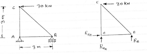
Answer 1) Consider FAB of Truss, Applying conditions of equilibrium,
 = 0
= 0
RHA + 30 Kn
 = 0
= 0
RvA + RB =0
Taking moment at point A, = 0
= 0
-(RB* 3) - (30*3) = 0
RB = -30 KN
RB =30 KN RVA = 30 KN
Consider Joint c, Assuming forces in member AC & BC to be
Tensile, applying conditions of equilibrium, 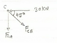
 = 0
= 0
-30 + FCB cos 45 =0
FCB =30/cos 45 = 42.42 KN (T)
-  = 0
= 0
- FcA – FCB sin 45=o
- F cA -42.42 sin 45 =0 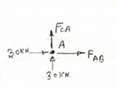
-FCA – 30= 0
-FCA = -30 KN
Consider Joint c, assuming forces in member AC & BC to be
Tensile, applying conditions of equilibrium,
 Fx = 0 30+FAB =0
FAB = -30KN
Question 2) Determine the forces in each member of the plane truss as shown in fig. In terms pf the external loading and state if the members are in tension or compression. Use 0+ 30 degree, L = 2 m and p =100N.
Diagram
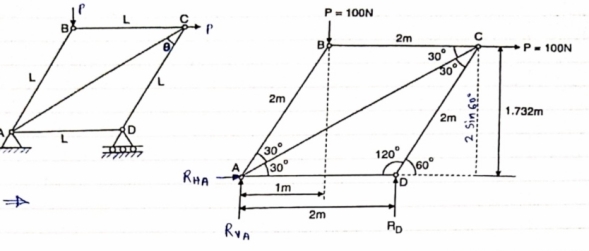
Answer 2) Consider FBD of Truss,
For equilibrium,  Fx =0
Fx =0
RHA+100 =0
RHA =-100 KN
 Fy =0 RVA = RD – 100 ….. 1
MA = 0 -------Taking moment @ A
- (Roxz) + (100*1) + (100*1.732) =0
- - 2 Rd + 100 + 1.7320 =0
- -2 Rd + 100 + 173.2 =0
- RD =136.66 N ()
From eqn (1)
RVA = 100 – 136.6
RVA= 36.6N
RVA = 36.6 N
Consider Joint D, for equilibrium,
Fx =0
-FAD + FCD cos 60 =0 – (11)
Fy = 0
136.6 +FCD sin 60 +0 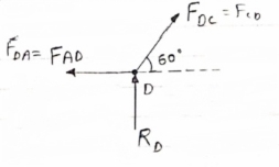
FCD = -157.73 N ©
From eqn (11), Fad =- 78. 87 N (c)
Consider point A, for the equilibrium of point A,
 Fx = 0
- 100 + FAD + FAc cos + 30 FAb cos60 = 0
-100 + (-78.87) +FAC cos 30 +FAb cos60 =0
FAc cos 30 + FAB cos60 + 178. 87 (3)
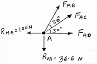
 fx =0
fx =0
-36.6 + FAC sin 30 + FAB sin 60 =0
FAC sin 30 + FAb sin 60 = 36.6
Solving eqn (3) and (4)
FAC = 273.21 N (T)
FAB = -115.47 N
FAB= 115.47 N ©
Consider point B, for the equilibrium of point,
 Fx =0
Fx =0
-FAB cos60 + FBC =0
-[9-115.47) cos60]+ FBC =0
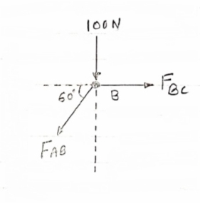
FBC = -57.73 N
FBC =57.73N
Member | AB | BC | CD | AD | AC |
Force | 115.47N | 57.73N | 157.73N | 78.87N | 273.21N |
Nature | c | c | c | c | T |
Question 3) Determine the axial forces in each member of the plane truss as shown in figure.
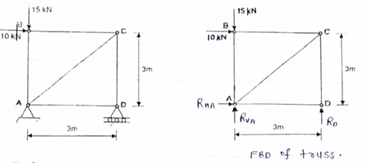
Answer 3) consider FBD of Truss,
For the equilibrium of Truss,  fx =0
fx =0
RHA + 10 =0
RHA = -10 KN
RHA =10KN (
Resolving forces vertically,
 fy =o
fy =o
RVA + RD -15 =0
RVA + RD = 15 …… (1)
Taking moment about point A,
 Fy =0
Fy =0
(10*3) – 3 Rd =0
30+ 3 Rd =0
RD= 10 KN 
RVA = 5KN ( )
)
Now Consider joint B, FBD of joint B is shown below.
Assumbing forces developed in all members to be Termile,
For the equilibrium of joint We have
 fx =0
fx =0
10+FBC =0 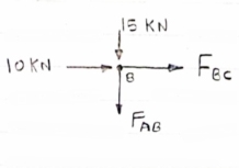
FBC = -10 KN
FBC = 10KN (c)
 fy =0
fy =0
FAB = -15 KN
FAB = 15 KN (c)
Now consider joint c,
For the equilibrium of joint,
 fx =0
fx =0
-FBC – FAC cos 45 =0
- (-10) – FAC cos 45=0
10= FAC cos 45
FAC = 10/cos 45 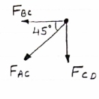
FAc = 14.14 KN (T)
 fy =0
fy =0
-Fac sin 45 – FCD=0
- 14.14 sin45 = FCD
FCD = -10 KN (c)
FCD= 10 KN (c)
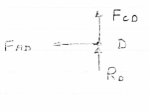
Consider joint D,
By observation,
FAD=0
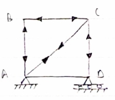
Sr .No | Member | Force | Nature |
1 | AB | 15 KN | c |
2 | BC | 10KN | c |
3 | CD | 10KN | c |
4 | DA | 0 | - |
5 | AC | 14.14 | T |
Question 4) Member AB & BC can support a maximum compressive force of 800 N & members AD, DC, BD can support a max. Tensile. Force of 2000N Determine the greatest land p that
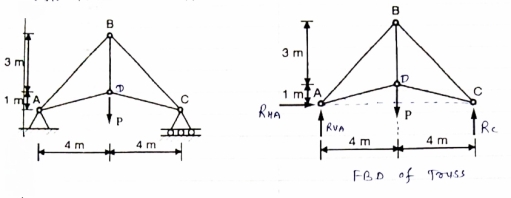
Answer 4) Consider following geometry of the figure.
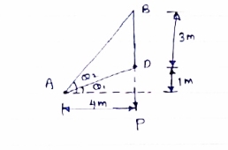
Tan 1 = ¼
1 = ¼
 14.04
14.04
 2 =
2 =  =45
=45
 Consider
 fx =0 RHA = 0
∈Fy =o RVA + Rc = p………(1)
∈ma =0
Hp- 8 Rc =0
Rc =P/2 N ( ) RvA = (P/2) N (
 )
)
Consider point A C assuming all forces as Tensile)
∈fx =0
FAD cos 14.04+FAB cos 45 =0… (2)
∈fy = 0 p/2= Fad sin 14.04 + FAB sin 45 =0….. (3)
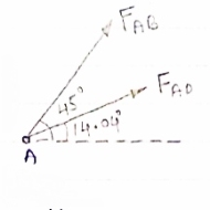
FAB = 2743.9 N > 800 N ( Not Allowed)
Let FAD = 2000 N (T) Then from eqn (2) & (3)
FAB =-274.9 N > 800 ( Not allowed)
Let FAB = .800 N ©, Then put this eqn (2) (3) we get
FAB = 583 N < 2000 N (Allowed) From Eqn (2) P= 848.9 N
Question 5) Explain type of truss?
Answer 5) TYPES OF TRUSSES
- Simple truss – indicates a single triangular truss. These trusses are most often used as the roof trusses.
2. Planar truss – as the name implies it is a two dimensional truss. If all the members and the nodes are in a planar surface, then this truss is a planar truss.
3. Space frame truss – Contrast to planar truss, the members and the nodes are located in the three dimensional space. Electrical and telecom towers are the one of the simplest example that we are seeing in the day to day life.
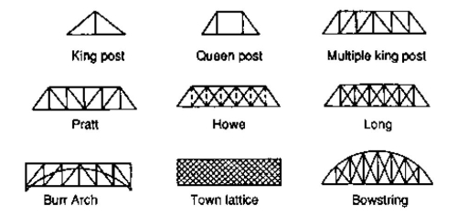
Question 6) Explain forms of truss?
Answer 6) FORMS OF TRUSSES
1. Pratt truss

Pratt truss form for the loads in gravity direction

Pratt truss form for the uplift loads (loads opposite to gravity)
2. Warren truss

3. North light truss

4. Vierendeel truss

King post truss, Bowstring truss, Queen post truss, Flat truss, Lenticular truss are some other forms of trusses in the use of the industry.
Question 7) Explain perfect and imperfect truss?
Answer 7)
Perfect Truss
A Truss said to be Perfect Truss if it fulfil the below condition
m=2j-3
Where
m= number of members
j= number of joints
Perfect Truss does not collapse under loading.
Imperfect or Deficient Truss
If given member in the structure is less than the required member than it is called imperfect or deficient truss.
The condition of Deficient Truss is
m<2j-3
Where
m= number of members
j= number of joints
Deficient Truss collapse when we apply load on it.
Question 8) Explain free body Diagram
Answer 8)
Free-body diagrams are diagrams used to show the relative magnitude and direction of all forces acting upon an object in a given situation. A free-body diagram is a special example of the vector diagrams that were discussed in an earlier unit. These diagrams will be used throughout our study of physics. The size of the arrow in a free-body diagram reflects the magnitude of the force. The direction of the arrow shows the direction that the force is acting. Each force arrow in the diagram is labelled to indicate the exact type of force. It is generally customary in a free-body diagram to represent the object by a box and to draw the force arrow from the centre of the box outward in the direction that the force is acting. An example of a free-body diagram is shown at the right.
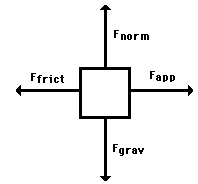
The free-body diagram above depicts four forces acting upon the object. Objects do not necessarily always have four forces acting upon them. There will be cases in which the number of forces depicted by a free-body diagram will be one, two, or three. There is no hard and fast rule about the number of forces that must be drawn in a free-body diagram. The only rule for drawing free-body diagrams is to depict all the forces that exist for that object in the given situation. Thus, to construct free-body diagrams, it is extremely important to know the various types of forces. If given a description of a physical situation, begin by using your understanding of the force types to identify which forces are present. Then determine the direction in which each force is acting. Finally, draw a box and add arrows for each existing force in the appropriate direction; label each force arrow according to its type. If necessary, refer to the list of forces and their description in order to understand the various force types and their appropriate symbols.
Question 9) Application of Equilibrium Concepts?
Answer 9)
1. The equilibrium constant has a definite value for every reaction at a particular temperature.
2. The value of equilibrium constant is independent of the original concentration of reactants.
3. The value of equilibrium constant tells the extent to which a reaction proceeds in the forward or reverse direction. If the value of K is larger, then the equilibrium concentration of the components on the right hand side of the reaction will be greater than the components on the left hand side of the reaction. Hence, the reaction proceeds to a greater extent and vice versa.
4. The equilibrium constant is independent of the presence of catalyst. This is because the catalyst affects the rate of forward reaction and backward reactions equally.
5. For a reversible reaction, the equilibrium constant for the forward reaction is inverse of the equilibrium constant for the backward reaction i.e., Kf=1/(Kb)
Question 10) Explain type of trusses?
Answer 10)
TYPES OF TRUSSES
4. Simple truss – indicates a single triangular truss. These trusses are most often used as the roof trusses.
5. Planar truss – as the name implies it is a two dimensional truss. If all the members and the nodes are in a planar surface, then this truss is a planar truss.
6. Space frame truss – Contrast to planar truss, the members and the nodes are located in the three dimensional space. Electrical and telecom towers are the one of the simplest example that we are seeing in the day to day life.
Simple Truss: It is possible to create a simple truss by joining three bars together to form a triangle. We can increase the size of the truss by adding two more members with an additional joint. By repeating this process, we can develop simple trusses with different shapes as shown below. The triangular building block assures internal stability of the truss structure as it is increased in size.

Although it is possible to have non-triangular cells in a simple truss, internal stability will not be guaranteed in that case.
Compound Truss: A compound truss is made up of simple trusses joined together to form a larger truss. The figure below shows a compound truss consisting of two simple trusses joined by a common joint and a bar. It is also possible to have multiple simple trusses joined together to create a larger compound truss. The connection of simple trusses then becomes a design issue determined based on the size of the resulting compound truss. Compound trusses are commonly used to support loads over long spans as in bridges.
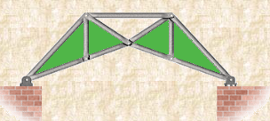
Complex Truss: A complex truss uses a general layout of members different from that used in simple and compound trusses. It often incorporates overlapping members.
