MRSPTU
ENGINEERING GRAPHICS AND DESIGN
UNIT 2
Theory of Projections
QUESTION BANKS
- What are the Principles of projection?
If straight lines are drawn from various points on the contour of an object to meet a plane, the object is said to be projected on that plane. The figure formed by joining, in correct sequence, the points at which these lines meet the plane, is called the projection of the object. The lines from the object to the plane are called projectors. Orthographic Projection is a method of producing dimensioned working drawings or blueprints of 3-D Objects using a series of related 2-D views of the object to communicate the object's length, width and depth.
The views are produced by using the fundamental concept of Orthographic Projection - the location of the Spectator (the viewer). The Spectator is always located at an infinite distance from the object and planes of reference - this means that the lines of sight (projection lines) remain parallel and will project on to a Plane which is perpendicular to the projection lines.
The primary views used are called the Elevation, Plan and End Elevation and are produced by projecting an image of the object as viewed by a spectator standing at infinity on to the Planes of Reference which are then folded flat to produce a 2-D drawing.
2. What are the Methods of projection?
Following four methods of projection are commonly used,
- Orthographic projection.
- Isometric projection.
- Oblique projection.
- Perspective projection.
In the above methods 2, 3 and 4 represent the object by a pictorial view as eyes see it. In these methods of projection, a three-dimensional object is represented on a projection plane by one view only, while in the orthographic projection an object is represented by two or three views on the mutual perpendicular projection planes. Each projection view represents two dimensions of an object. For the complete description of the three-dimensional object at least two or three views are required.
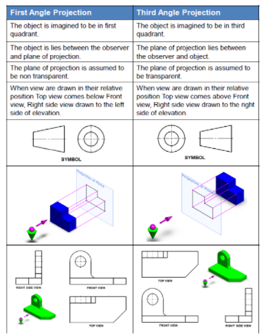
3. Explain First and third angle projections?
Every engineer must know how to read engineering drawings and the most integral part of this is knowing the difference between first and third angle projection. A collection of 2D drawings can be used to represent a 3D object in orthographic projection and consists of six orthographic views (Top, Bottom, Right, Left, Front and Back view) also known as six principle views. Out of these six, front, right side and top view are the most commonly used ones.
- First-angle projection: In this type of projection, the object is imagined to be in the first quadrant. Because the observer normally looks from the right side of the quadrant to obtain the front view, the objects will come in between the observer and the plane of projection. Therefore, in this case, the object is imagined to be transparent, and the projectors are imagined to be extended from various points of the object to meet the projection plane. When these meeting points are joined in order on the plane they form an image, thus in the first angle projection, any view is so placed that it represents the side of the object away from it. First angle projection is often used throughout parts of Europe so that it is often called European projection.
2. Third-angle projection: In this type of projection, the object is imagined to be in the third quadrant. Again, as the observer is normally supposed to look from the right side of the quadrant to obtain the front view, in this method, the projection plane comes in between the observer and the object. Therefore, the plane of projection is assumed to be transparent. The intersection of this plan with the projectors from all the points of the object would form an image on the transparent plane.
4. Explain Orthographic projections?
Let us suppose that a transparent plane has been set up between an object and the station point of an observer's eye (Fig. 1). The intersection of this plane with the rays formed by lines of sight from the eye to all points of the object would give a picture that is practically the same as the image formed in the eye of the observer. This is perspective projection.
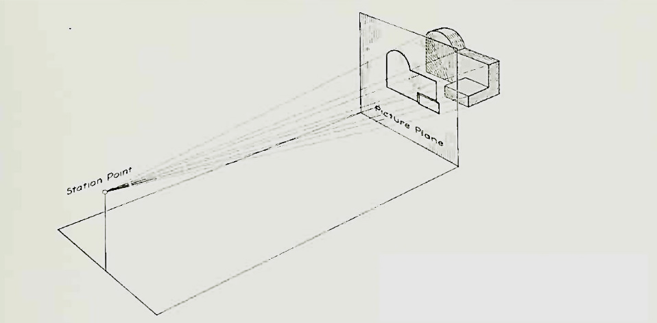
Figure 1 Perspective projection. The rays of the projection converge at the station point from which the object is observed.
If the observer would then walk backward from the station point until he reached a theoretically infinite distance, the rays formed by lines of sight from his eye to the object would grow longer and finally become infinite in length, parallel to each other, and perpendicular to the picture plane. The image so formed on the picture plane is what is known as "orthographic projection." See Fig.
2.
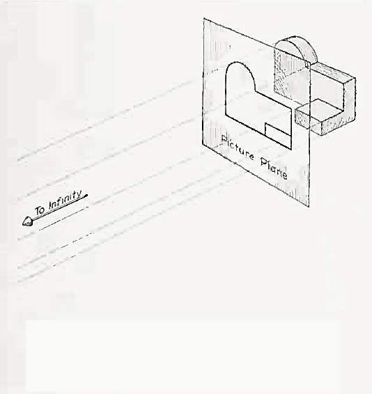
Orthographic projection.
Basically, orthographic projections could be defined as any single projection made by dropping perpendiculars to a plane. However, it has been accepted through long usage to mean the combination of two or more such views, hence the following definition has been put forward: Orthographic projection is the method of representing the exact shape of an object by dropping perpendiculars from two or more sides of the object to planes, generally at right angles to each other; collectively, the views on these planes describe the object completely. (The term "orthogonal" is sometimes used for this system of drawing.)
Orthographic views:
The rays from the picture plane to infinity may be discarded and the picture, or "view," thought of as being found by extending perpendiculars to the plane from all points of the object, This picture, or projection on a frontal plane, shows the shape of the object when viewed from the front, but it does not tell the shape or distance from front to rear. Accordingly, more than one projection are required to describe the object.
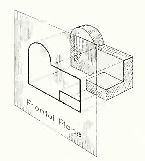
The frontal plane of projection. This produces the front view of the object.
In addition to the frontal plane, imagine another transparent plane placed horizontally above the object The projection on this plane, found by extending perpendiculars to it from the object, will give the appearance of the object as if viewed from directly above and will show the distance from front to rear.
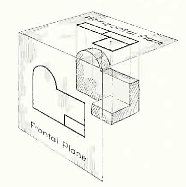
The frontal and horizontal planes of projections. Projection on the horizontal plane produces the top view of the object.
If this horizontal plane is now rotated into coincidence with the frontal plane, the two views of the object will be in the same plane, as if on a sheet of paper.
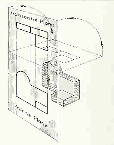
The horizontal plane rotated into the same plane as the frontal plane.
Now imagine a third plane, perpendicular to the first two. This plane is called a "profile plane," and a third view can be projected on it. This view shows the shape of the object when viewed from the side and the distance from bottom to top and front to rear.
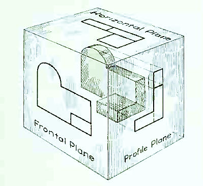
The three planes of projection: frontal, horizontal and profile. Each is perpendicular to other two.
The horizontal and profile planes are shown rotated into the same plane as the frontal plane (again thought of as the plane of the drawing paper). Thus, related in the same plane, they give correctly the three-dimensional shape of the object.
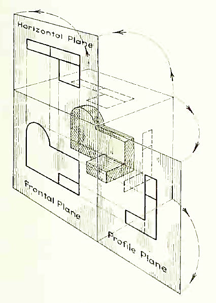
The horizontal and profile planes rotated into the same plane as the frontal plane. This makes it possible to draw three views of the object.
In orthographic projection the picture planes are called "planes of projection"; and the perpendiculars, "projecting lines" or "projectors."
5. Explain Isometric projection
Isometric projection is a type of pictorial projection in which the three dimensions of a solid are not only shown in one view, but their actual sizes can be measured directly from it.
If a cube is placed on one of its corners on the ground with a solid diagonal perpendicular to the V.P., the front view is the isometric projection of the cube. The step-by-step construction is shown in fig.1.
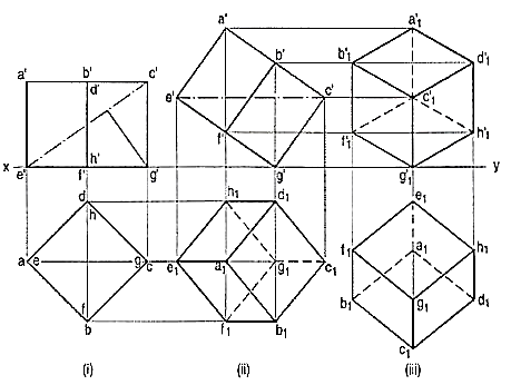
To draw the projections of a cube of 25 mm long edges resting on the ground on one of its corners with a solid diagonal perpendicular to the V.P., assume the cube to be resting on one of its faces on the ground with a solid diagonal parallel to the V.P.
(I) draw a square abed in the top view with its sides inclined at 45° to xy. The line ac representing the solid diagonals AG and CE is parallel to xy. Project the front view.
(ii) Tilt the front view about the corner g' so that the line e' c' becomes parallel to xy. Project the second top view. The solid diagonal CE is now parallel to both the H.P. And the V.P.
(iii) Reproduce the second top view so that the top view of the solid diagonal, viz. e1 c1 is perpendicular to xy. Project the required front view.
Figure shows the front view of the cube in the above position, with the corners named in capital letters. Its careful study will show that
(a) All the faces of the cube are equally inclined to the V.P. And hence, they are seen as similar and equal rhombuses instead of squares.
(b) The three lines CB, CD and CG meeting at C and representing the three edges of the solid right-angle are also equally inclined to the V.P. And are therefore, equally fore shortened. They make equal angles of 120° with each other. The line CG being vertical, the other two lines CB and CD make 30° angle each, with the horizontal.
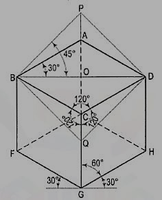
(c) All the other lines representing the edges of the cube are parallel to one or the other of the above three lines and are also equally foreshortened.
(d) The diagonal BO of the top face is parallel to the V.P. And hence, retains its true length.
This chapter deals with various topics of isometric projection as shown below:
1. Isometric axes, lines and planes
2. Isometric scale
3. Isometric drawing or isometric view
4. Isometric graph.