MRSPTU
ENGINEERING GRAPHICS
UNIT 4
Projections of lines
Question banks
- Explain First and third angle projections?
First-angle projection: In this type of projection, the object is imagined to be in the first quadrant. Because the observer normally looks from the right side of the quadrant to obtain the front view, the objects will come in between the observer and the plane of projection. Therefore, in this case, the object is imagined to be transparent, and the projectors are imagined to be extended from various points of the object to meet the projection plane. When these meeting points are joined in order on the plane they form an image, thus in the first angle projection, any view is so placed that it represents the side of the object away from it. First angle projection is often used throughout parts of Europe so that it is often called European projection.
Third-angle projection: In this type of projection, the object is imagined to be in the third quadrant. Again, as the observer is normally supposed to look from the right side of the quadrant to obtain the front view, in this method, the projection plane comes in between the observer and the object. Therefore, the plane of projection is assumed to be transparent. The intersection of this plan with the projectors from all the points of the object would form an image on the transparent plane.
2. Draw projections of a 80 mm long line PQ. Its end P is 10 mm above HP and 10 mm in front of VP. The line is parallel to VP and inclined to HP at 30°.
Solution steps:
1) Draw the plan and elevations of the end point P.
2) Draw plan PQ of the line at an angle of 30° to XY.
3) Draw the projector of Q.
4) From the elevation of end point P draw a line parallel to XY meeting projector of Q at Q´.
5) P´Q´ is the elevation and PQ is the plan of the line.

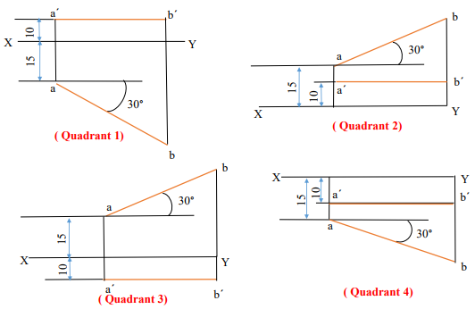
3. A straight line AB of 40 mm length has one of its ends A, at 10 mm from the HP and 15 mm from the VP. Draw the projections of the line if it is parallel to the VP and inclined at 30° to the HP. Assume the line to be located in each of the four quadrants by turns.

4. A straight line AB of 40 mm length is parallel to the HP and inclined at 30° to the VP. Its end point A is 10 mm from the HP and 15 mm from the VP. Draw the projections of the line AB, assuming it to be located in all the four quadrants by turns.

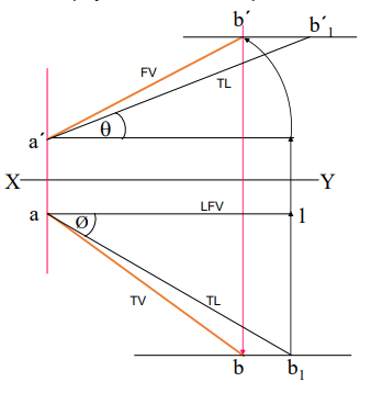
5. Line AB is 75 mm long and it is 300 & 400 inclined to HP & VP respectively. End A is 12mm above HP and 10 mm in front of VP. Draw projections. Line is in 1st quadrant.
Solution steps:
- Draw XY line and one projector.
- Locate a´ 12mm above XY line & a 10mm below XY line.
- Take 300 angle from a´ & 400 from a and mark TL, i.e., 75mm on both lines. Name those points b1 ´ and b respectively.
- Draw horizontal component of TL a b1 from point b1 and name it 1. (the length a-1 gives length of FV as we have seen already)
- Extend it up to locus of a and rotating a’ as center locate b´ as shown. Join a´ b´ as FV.
- From b´ drop a projector downward & get point b. Join a & b, i.e., TV.

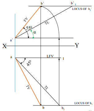
6. Line AB 75mm long makes 450 inclination with VP while it’s FV makes 550 . End A is 10 mm above HP and 15 mm in front of VP. If line is in 1st quadrant draw it’s projections and find it’s inclination with HP.
Solution Steps:-
1.Draw xy line.
2.Draw one projector for a’ & a
3.Locate a´ 10mm above XY & a 15 mm below XY.
4.Draw a line 450 inclined to XY from point a and cut TL 75 mm on it and name that point b1.
5.Draw locus from point b1.
6.Take 550 angle from a´ for FV above XY line.
7.Draw a vertical line from b1 up to locus of a and name it 1. It is horizontal component of TL & is LFV.
8.Continue it to locus of a´ and rotate upward up to the line of FV and name it b´. This a´ b´ line is FV. 9. Drop a projector from b´ on locus from point b1 and name intersecting point b. Line ab is TV of line ab.
10.Draw locus from b´ and with TL distance cut point b1 ´ 11.Join a´ b1 ´ as TL and measure it’s angle α at a´. It will be true angle of line with HP.

7. FV of line AB is 500 inclined to XY and measures 55 mm long while it’s TV is 600 inclined to XY line. If end A is 10 mm above HP and 15 mm in front of VP, draw it’s projections, find TL, inclinations of line with HP & VP.
Solution steps:
1.Draw XY line and one projector.
2.Locate a’ 10 mm above XY and a 15 mm below XY line.
3.Draw locus from these points.
4.Draw FV 500 from a’ and mark b’ cutting 55mm on it.
5.Similarly draw TV 600 from a & drawing projector from b’ locate point b and join a b.
6.Then rotating views as shown, locate True Lengths ab1 & a’b1 ’ and their angles with HP and VP.

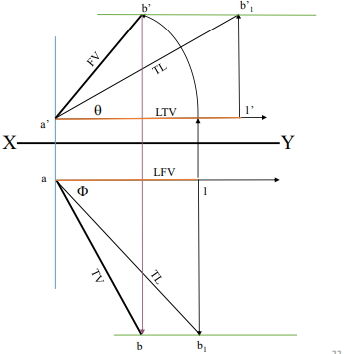
8. Line AB is 75 mm long. It’s FV and TV measure 50 mm & 60 mm long respectively. An end is 10 mm above HP and 15 m
SOLUTION STEPS:
1.Draw XY line and one projector.
2.Locate a’ 10 mm above XY and a 15 mm below XY line.
3.Draw locus from these points.
4.Cut 60mm distance on locus of a’ & mark 1’ on it as it is LTV.
5.Similarly cut 50mm on locus of a and mark point 1 as it is LFV.
6.From 1’ draw a vertical line upward and from a’ taking TL (75mm ) in compass, mark b’1 point on it. Join a’ b’1 points.
9. Draw locus from b’1 8. With same steps below get b1 point and draw also locus from it.
Now rotating one of the components i.e., a-1 locate b’ and join a’ with it to get FV.
Locate TV similarly and measure and angles
