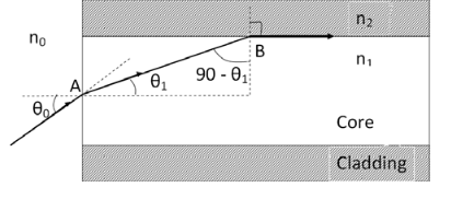
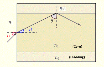
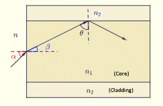
Figure – Total Internal Reflection |
Hence at critical angle θ1= θc and θ2= 90o . Using Snell‘s law: n1 sin θ1 = n2 sin θ2 n1 sin θc = n2 sin90o sin θc = n2 / n1 θc = sin-1 (n2 / n1) |
|
According to Snell’s law at point A n0 Sin θ0 = n1 Sin θ1 Sin θ0= (n1 / n0) Sin θ1 ………(1) According to Snell’s law at point B n1 Sin(90- θ1) = n2 Sin90 ………(2) n1 Cosθ1 = n2 as (Sin90=1) Cosθ1 = n2 /n1 Sinθ1 = (1-Cos2 θ1)1/2 Sinθ1= (1- (n2 /n1)2)1/2 Sinθ1= ( n12- n22 )1/2/ n1 ………(3) We know Sin θ0= (n1 / n0) Sin θ1 from equation (1) Substitute the value of Sinθ1 from equation (3) Sinθ0= (n1 / n0) *( n12- n22 )1/2/ n1 On simplification Sinθ0= ( n12- n22 )1/2/ n0 θ0=Sin-1 ( n12- n22 )1/2/ n0 Acceptance Angle is θ0=Sin-1 ( n12- n22 )1/2/ n0 ………(4) |
Figure |
NA = Sin(acceptance angle) NA = Sin {Sin-1 (( n12- n22 )1/2/ n0)} from equation (4) NA = (( n12- n22 )1/2/ n0) ………(5) If the refractive index of the air medium is unity i.e. n0=1 put in (5) NA = ( n12- n22 )1/2 ………(6) Fractional change in refractive index ∆= (n1- n2)/ n1 n1∆ = (n1- n2) ………(7) from equation (6), we have NA = {( n1- n2 )( n1+n2 )}1/2 NA = { n1∆ (n1+n2 )}1/2 as n1∆ = (n1- n2) by Eq(7) NA = { n1∆ 2n1}1/2 n1 ≈ n2, so n1+n2 =2n1 NA = n1{2∆}1/2 |
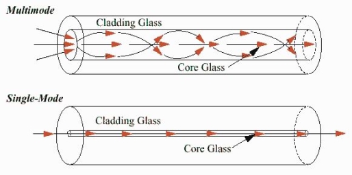
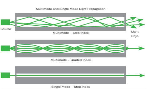
Structure: Core diameter : 5-10μm Cladding diameter : Generally around 125μm Protective layer : 250 to 1000μm Numerical aperture : 0.08 to 0.10 Bandwidth : More than 50MHz km.
|
|
Structure: Core diameter : 50-350μm Cladding diameter : 125μm - 500μm Protective layer : 250 to 1100μm Numerical aperture : 0.12 to 0.5 Bandwidth : Less than 50MHz km. |
|
Figure: 23 |
Figure |
Figure
|
|
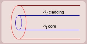
Figure: Schematic of an optical fiber
|
Figure: (optical fiber with core, cladding and total internally reflected ray) |
Figure: Total Internal Reflection
Figure: Optical Fibre |
Figure: Representation of Optical Fibre
|
Numerical aperture (NA)
|
(a) we know that n0 = nair = 1.0003. The numerical aperture is therefore NA = n0 sin θ0max = (1.0003) sin (8.50o) = 0.148. (b) The index of refraction of the cladding can be found from the numerical aperture: n12 - n22 = NA2. (c) We know that that the n0 = nwater = 1.33. Since the numerical aperture is a property of the fiber and only depends upon n1 and n2, it will not change when the medium outside the fiber changes. The cut-off angle, however, will have to change if the numerical aperture is to be unaffected by a change in n0: NA = 0.148.
|
|
a) the critical angle θc at the core - cladding interface.
b) the numerical aperture N.A. of the optical fiber
c) the angle of acceptance αmax of the the optical fiber system.
A12)
a) θc = sin-1 (n2 / n1) = sin-1 (1.45 / 1.46) = 83.29 ° |
|
a) angle of refraction β at the outside - core interface.
b) angle θ
c) and explain why this light ray will be reflected at the core - cladding interface and hence guided along the fiber.
A13)
a) Angle β is found using Snell's law at the outside - core interface as follows |
A14) An optical fibre is characterized by one more important parameter, known as V-number which is more generally called normalized frequency of the fibre. It is given by the relation
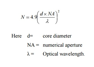
V – number determines how many modes a fiber can support, It is given by, V = Where d is the diameter of the core, l is the wavelength of light used NA is the numerical aperture of the fibre. V = Or V = If V ≤ 2.405, then the fibre is single mode fibre (SMF) If V > 2.405, then the fibre is multimode fibre (MMF)
|
d = 2r = 2 x 50 x 10-6 m V = =94.72= normalized frequency Total number of guided mode = M = V2/2 = 4486.
|
Given :z=8km P(0) = 120 μW P(z) = 3 μW
a) Overall attenuation is given by,
αp (dB/km ) = 10. log
b) Overall attenuation for 10 km, Attenuation per km = αp (dB/km ) = = Attenuation in 10 km link = 2.00 x 10 = 20 dB In 10 km link there will be 9 splices at 1 km interval. Each splices introducing attenuation of 1 dB. Total attenuation = 20 dB + 9 dB = 29 dB |

