Unit - 5
Introduction to Beams
Q1) What is Beams?
A1)
Beams are structural elements subjected to transverse loads in the plane of bending causing bending moments and shear forces.
Symmetrical b sections about z-z axis (major axis) are economical and geometrical properties of such sections are available in SP (6).
The compression flange of the beams can be laterally supported (restrained) or laterally unsupported (unrestrained) depending upon whether restraints are provided or not.
The beams are designed for maximum BM and checked for maximum SF, local effects such as vertical buckling and crippling of webs and deflection. Section 8 (IS 800-2007) shall be followed in the design of such bending members.
Q2) What are types of sections?
A2)
Beams can be different cross sections depending on the span and loadings.
1. Simple I section
2. I section with cover plate
3. Two I section with cover plate
4. Built-up I section
5. Gantry girder
6. Box sections
7. Castled beams
8. Two I placed one above the other
1) Simple I section: Use of simple I section is normal span and loading
2) I section with cover plate: Use of I section with cover plate is heavy load and larger span
3) Two I section with cover plate: it is use of very heavy load with large span
4) Built-up I section: it is used to plate girder where span exceed 20 m and loads are heavy.
5) Gantry girder: Gantry girder is use for movable heavy loads, lift loads etc.
6) Box sections: It is use for service lines
7) Castled beams: It is use for light loads and large span
8) Two I placed one above the other: It is used for light loading with large span
Q3) Explain Behaviour of Beam in Flexure?
A3)
In order to expect the flexural behavior of any brittle fabric like concrete, load deflection technique on 3 factors become essential. The 3 factor technique is the manner to compute the deflections because of implemented masses so as to investigate the flexural behavior.
RCC beam are efficiently used as structural participants in diverse constructions. RCC is a homogeneous material which is having diverse properties.
RCC beams are classified as under strengthened, balanced and over strengthened sections on the evaluation basis. In RCC each concrete and steels will reaches the pressure and corresponding lines because of outside subjected hundreds concurrently.
When in an RCC beam, if the metallic has a tendency to fail earlier than the pressure in concrete reaches the maximum permissible pressure such beams are known as under strengthened sections. If each concrete and metallic reaches the permissible pressure values concurrently such beams are taken into consideration as balanced sections. If the concrete has a tendency to fail earlier than the pressure in metallic reaches the maximum permissible pressure such beams are taken into consideration as over strengthened sections. In the following article primarily based totally on the laboratory experimental evaluation the flexure behavior of diverse sections are discovered through damaging methods.
DESIGN CRITERIA
The primary layout criterion for any form of shape is safety, serviceability and economy. Due to these primary esteem properties of RCC elements, they are abundantly used in all structural applications. For the structural use of RCC elements it must obey the following parameters. The shape must be secure and economical that it can perfectly resist both tension and compressive stress. The shape must be stiff and look like unblemished such that it ought to be resisted the bending moments and shear forces because of outside applied masses.
The shape must be economical by means of it can be able to resist all type of stress and availability of substances to make RCC. In order to are expecting the secure and monetary situations of RCC it's far essential to evaluate the situations of remaining masses and corresponding deflections below precise constrains.
To attain the applicable outcomes, one had to behavior an experimental analysis. When an RCC beam is subjected to a few outside loadings the beam tends to bend with a few deflections due to loading. At any point in the cross section of the beam is considered the pressure distribution can be such that everyone the fibers above the impartial axis by skip thru the CG are in compression, while all of the fibers beneath the impartial axis are in tension.

Q4) What are classification of section?
A4)
Classification:
- Plastic section
- Compacted section
- Semi-compacted section
- Slender section
Plate elements of a cross-section may buckle locally due to compressive stresses. The local buckling can be avoided before the limit state achieved by limiting the width to thickness ratio of elements (i.e., web and flange) of a cross-section subjected to compression due to axial force, moment or shear.
On the basis of above four classes of sections are defined as follows:
(1) Class 1 (plastic)
Cross-sections which can develop plastic hinges and have the rotation capacity required for failure of the structure by formation of plastic mechanism. The width to thickness ratio of plate elements shall be less than that specified under class 1 (plastic)
(2) Class 2 (compact)
Cross sections which can develop the plastic moment of resistance, but have inadequate plastic hinge rotation capacity for the formation of plastic mechanism due to local buckling
The width to thickness ratio of plate element shall be less than that specified under class 2 (compact), but greater than the specified under class (plastic)
(3) Class 3 (Semi-compact)
Cross sections in which the extreme fiber in compression can reach yield stress, but cannot develop plastic moment of resistance due to local buckling. The width to thickness ratio of plate elements shall be less than that specified under class 3 (semi-compact) but greater than the specified under class 2 (compact)
(4) Class 4 (Slender)
Cross sections in which the elements buckle locally even before reaching yield stress. The width to thickness ratio of plate elements shall be greater than that specified under class 3 (semi compact)
In such class, the effective sections for design shall be calculated by deducting the width of the compression plate element in excess of the semi-compact section
When different elements of a cross-section fall under different classes
The section shall be classified as governed by the most critical element. The maximum value of limiting width to thickness ratios of elements for different classifications of sections are given in (Table - 2 IS 800-2007).
Q5) Explain Lateral Stability of Beams?
A5)
Simply defined, lateral balance is the belongings of an item to broaden forces or to have forces imposed upon it that repair it to or keep its authentic condition (position).
Lateral balance is normally supplied for a beam, a column, a metal or timber frame, or a wall with lateral bracing.
Lateral balance is usually supplied for a beam, a column, a metal or wooden body, or a wall with lateral bracing.
Lateral bracing is the structural thing that stops the beam or column from twisting or buckling sideways or the structural thing that stops the metal body, wooden body, or wall from falling over.
In the case of a beam, the pinnacle of the beam is frequently laterally braced with the aid of using joists (open internet metal joists that seem like trusses or I- or C-formed member) that body into the facet of it or with the aid of using attaching the ground deck or roof deck to the pinnacle of the beam.
A column is usually braced within side the lateral route with the beams that body into its sides.
The lateral bracing for a metal body, a wooden body, or a masonry wall is commonly offer intermittently with the aid of using the ground deck or close to its pinnacle with the aid of using the roof deck in mixture with diagonal bracing and/or move walls.
Lateral bracing prevents a metal body, a wooden body, or a masonry wall from falling over below its very own weight or throughout publicity to an effect or wind pressures.
It is uncommon for a beam, a column, a metal or wooden body, or a wall in a finished shape to be inadequately braced within side the lateral route due to the fact they may be commonly deliberately or inadvertently braced with the aid of using the adjoining structural additives formerly mentioned. However, lateral instability isn't always unusual throughout the development or demolition levels.
During those levels lateral balance ought to be taken into consideration and brief lateral bracing supplied wherein necessary.
Lateral bracing is usually supplied throughout the volatile levels with brief man wires, diagonal braces, X-bracing, bracing to a close-by finished shape, etc.
Q6) What is Lateral‐Torsional Buckling?
A6)
The lateral torsional buckling is the deformation of the beam due to the applied loads away from its longitudinal axis. Further, it causes steel beams failures. The deformation could occur as translational and rotational movement of the section, and these types of movements are identified as lateral torsional buckling.
The lateral torsional buckling is the deformation of the beam due to the applied loads away from its longitudinal axis. Further, it causes steel beams failures.
The deformation could occur as translational and rotational movement of the section, and these types of movements are identified as lateral torsional buckling. Figure 1 indicates the deformations that can be seen as a result of lateral torsional buckling.
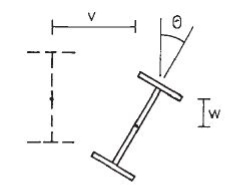
Figure: Lateral Torsional Buckling
As indicated in Figure, the beam can be decoded with the application of loads. This deformation could occur laterally and vertically with a rotation of the member. In the design of steel beams, lateral restrains are provided in spacings calculated to avoid failures.
Lateral torsional buckling occurs with the increase of loads based on section properties and it restrains. Loading on a beam cannot be avoided as it is the purpose of having the beam.
However, the section properties and the restrain conditions can be controlled during construction and design.
- As discussed above too, lateral-torsional buckling occurs when the beam is not full restraints in the lateral direction along the compression flange of the beam.
- The beam is considered full restraint laterally when the connection between the beam and the floor can resist at least a lateral force of 2.5% of the maximum force in the compression flange of the beam.
When there are no restraints, it is required to provide sections having higher section modulus, if the restraints are provided properly, the size of the beam can be reduced.
It is a proven fact that failures cause the moment of the section away from its axis. Therefore, providing the restrains will definitely reduce the section dimensions.
However, based on the structural arrangement of the structure, there may not be able to provide the lateral restrains at ends or internally. In such situations, beams need to be designed without considering the lateral restrains.
Mainly, the failures to restrain the compression flange cause the lateral movement of the section. Therefore, lateral-torsional buckling can be avoided by providing internal restrains.
Intermediate restraints are provided to reduce the unsupported length in the lateral direction. They should be capable of resisting lateral forces and should have the capacity to retain without deforming. The axial capacity of intermediate restrains shall be checked as per the guidelines in the BS 5950.
Design for Lateral Torsional Buckling of Beam
Section to satisfy the bending requirements, it shall have the bending capacity in the direction of bending (Mc) greater than the applied bending moment and lateral torsional buckling capacity greater the moment generated due to the buckling.
Mx < Mb/mLT and Mx ≤ Mc
In this article, the procedure needs to be followed in calculating the lateral-torsional buckling capacity is discussed. And the article steel beam design to bs 5950 could be referred bending capacity checks.
Lateral Torsional Buckling resistance (Mb/mLT) can be calculated as illustrated below.
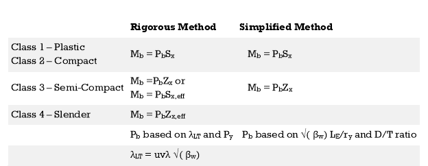
Two methods used to evaluate the Buckling Resisting Moment (Mb). Based on the preference of the designer, either method could be used.
- Rigorous method
- Simplified method
When both methods are compared, it seems that the main difference is the method of evaluating the Bending Strength (Pb).
A detailed explanation of the method of designing as a steel beam is discussed in the article steel beam design worked example.
Check Lateral Torsional Buckling
Lateral torsional buckling Example
Data:
- Consider simply supported beam with not intermediate restraints
- Beam span 6m
- Maximum design bending moment 100 kNm
As discussed above there are two methods for checking the lateral-torsional buckling. Let’s discussed them with a worked example.
It is required to satisfy the following equation for a section to be ok for buckling.
Mx < Mb / mLT
For simplicity, in this example, no intermediate restraints are considered.
Then,
mLT = 0.925, Table 18, BS 5950
Mb = Pb Sx Cl. 4.3.6.4
Firstly, let’s check the buckling capacity with rigorous method.
The following section data are considered in the calculation
- D = 500 mm
- T = 16 mm
- t = 10 mm
- B = 200 mm
- b = 100 mm
- r1 = 20 mm
- d = 500 – 16 x 2 – 2 x 20 = 428 mm
- Sx = 2175×103 mm3
- Zx = 1914×103 mm3
- ry = 43.3 mm
- Section is plastic as per its dimensions
Rigorous Method
Mb = Pb Sx
Pb is function of λLT and Py
λLT = uvλ√(βw)
λ = LE / ry
LE – can be found from Table 13 (Cl. 4.3.5.1) and consider LLT = L – span
Thus,
LE = 1.0 LLT = 1 x 6 = 6 m
λ = LE / ry = 6000 / 43.3 = 138.568
For rolled I and H sections, Cl. 4.3.6.8
x = D / T used with u = 0.9
x = D / T = 500 / 16 = 31.25
βw can be obtained from the Cl 4.3.6.9
βw = 1 for Class 1 plastic or Class 2 Compact sections
v – Slenderness factor – obtained from Table as per the λ / x and η
λ / x = 138.568 / 31.25 = 4.434
For equal flanges η = 0.5
v = 0.84 from Table [conservative value taken; λ / x = 4.5, interpolation shall be used for exact value]
λLT = uvλ√(βw) = 0.9 x 0.84 x 138.568 x √ (1) = 104.8
λLO to be obtained from Table 16 (indicated at the bottom of the Table)
If λLO ≥ λLT; Pb = Py or Otherwise Pb shall be taken from Table for rolled sections.
If λLO ≥ λLT no allowance needs to be made for lateral-torsional buckling and otherwise check for lateral-torsional buckling.
Py = 275 N/mm2; λLO = 34.3
λLO <λLT
Hence, check for lateral torsional buckling
From Table, for λLT = 104.8; Pb = 117 N/mm2
Mb = Pb Sx = 117 x 2175 x 103 x 10-6 = 254.5 kNm
Mb / mLT = 254.8 / 0.925 = 275.4 kNm
Therefore, Mx = 100 kNm < Mb / mLT = 239.838 kNm
Section is adequate for lateral torsional buckling as per the rigorous method.
Simplified Method
We need not doing both the calculation to check the buckling resistance.
Mb = Pb Sx: Cl. 4.3.7
The determination of the Pb is not the same as the rigorous method.
This method provides conservative answers.
Pb can be obtained from Table 20 of BS 5950 as per √(βw) (LE / ry) and D / T
βw = 1; as previous calculation.
LE / ry = 138.568; from above calculations
√(βw) (LE / ry) = 10.5 x 135.568 = 138.568
D / T = 500 / 16 = 31.25
Now, can obtain from Table 20
Pb = 116.646 N/mm2
Mb = Pb Sx = 116.646 x 2175 x 103 x 10-6 = 253.705 kNm
Mb / mLT = 253.705 / 0.925 = 274.3 kNm
Thus, Mx = 100 kNm < Mb / mLT = 274.3 kNm
Therefore, the section is adequate.
Q7) What is mean by Bending Strength of Beams?
A7)
The design of beam consists of selecting a section based on plastic sectional modulus and checking for its shear capacity deflection, web crippling and web buckling. Most of equation available in IS 800-2007
Design bending strength
1) If V> 0.6Vd
Or
V< 0.6Vd
Then

For simply supported beams

Where,


2) If V>0.6Vd
Then Md= Mdv
Where
Md= Design of bending strength under high shear

For plastic and compact sections
= 

Q8) Explain Laterally Supported Beams?
A8)
Beams subjected to BM develop compressive and tensile forces and the flange subjected to compressive forces has the tendency to deflect laterally. This out of plane bending is called lateral bending or buckling of beams. The lateral bending of beams depends on the effective span between the restraints, minimum moment of inertia (Iyy) and its presence reduces the plastic moment capacity of the section.
Beams where lateral buckling of the compression flange are prevented are called laterally restrained beams. Such continuous lateral supports are provided in two ways:
i) The compression flange is connected to an RC slab throughout by shear connectors.
Ii) External lateral supports are provided at closer intervals to the compression flange so that it is as good continuous lateral support. Cl 8.2.1 (pg - 52 and 53) gives the specifications in this regard.
Design of such laterally supported beams are carried out using Clauses 8.2.1.2, 8.2.1.3, 8.2.1.5, 8.4, 8.4.1, 8.4.1.1, 8.4.2.1 and 5.6.1 (Deflection) In addition, the beams shall be checked for vertical buckling of web and web crippling. The design is simple, but lengthy and does not involve trial and error procedure.
- Calculate the factored load and the maximum bending moment and shear force
- Obtain the plastic section modulus required
Zp = (M*Vmo /Fy)
a suitable section for the beam-ISLB, ISMB, ISWB or suitable built-up
Sections (doubly symmetric only). (Doubly symmetric, singly symmetric
And asymmetric- procedures are different)
3. Check for section classification such as plastic, compact, semi-compact or slender. Most of the sections are either plastic or compact. Flange and web criteria.

4. Calculate the design shear for the web and is given by

5. Calculate the design bending moment or moment resisted by the section (for plastic and compact)

6. Check for buckling
7. Check for crippling or bearing
8. Check for deflection
Q9) Explain Laterally Unsupported Beams?
A9)
Beams subjected to BM develop compressive and tensile forces and the flange subjected to compressive forces has the tendency to deflect laterally. This out of plane bending is called lateral bending or buckling of beams. Lateral buckling of beams involves three kinds of deformations namely lateral bending, twisting and warping. The lateral bending of beams depends on the effective span between the restraints, minimum moment of inertia (Iyy) and can reduce the plastic moment capacity of the section.
The value of Mer can be calculated using the equations given in cl. 8.2.2.1 pg-54 for doubly symmetric c/s and annex E (pg 128-129) for c/s symmetrical about the minor axis. The design bending compressive strength can be calculated using a set of equations as specified in cl.8.2.2 (Table 13a and 13 pg-54 to 57.
- Calculate the factored load and the maximum bending moment and shear force
- Design of LSB is by trial-and-error method. The design bending stress is significantly less which is to be assumed to start with. Assume slenderness ratio and h/tf and get the corresponding critical bending stress and hence the corresponding design bending stress.
- Determine the required plastic section modulus and select the section.
- Determine the actual design bending stress of this selected section knowing its slenderness ratio which should be greater than that assumed previously. Otherwise revise the section.
- Check for shear, buckling, crippling and deflection should be done Design bending strength can be calculated as per IS: 800
Design bending strength can be calculated as per IS: 800


 rolled or welded sections
 can b Elastic lateral buckling,
Torsional constant, 
Warping constant, 
Q10) What is Shear Strength of Beams?
A10)
Shear strength:
Shear forces always exists with BMS and the maximum shear stress has to be checked with the shear yield stress. Shear stresses can become important if the depth of the beams are restricted and when beams are subjected to large concentrated loads near the supports. The distribution of shear stress at limit state (plastic) is shown below
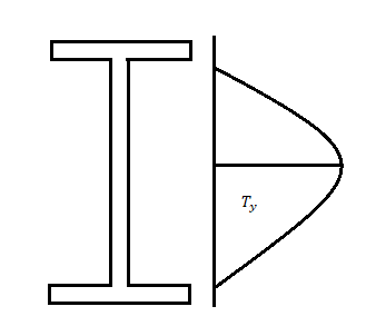
The nominal shear yielding strength is based on the Von Mises yield criteria which assumes wide and thin webs without any local failures. The shear strength is expressed as

Fyw = yield strength of the web
The design strength

Av = Shear area as specified in cl. 8.4.1.1 pg-59
The web can buckle elastically or in elastically depending on the ratio of d/tw if this ratio exceeds 67E
Where,
€ =  and d = clear depth of the web between flanges, resistance to shear buckling has to be verified
Shear failure can occur due to excessive yielding of the web area if the shear capacity is exceeded. The beam will be a high shear condition if V > 0.6 V, and the moment capacity of the section decreases and has to calculated using the provisions given in cl. 9.2.2 pg 70.
Q11) What is Web Buckling?
A11)
Web buckling:
The web of the beam is thin and can buckle under reactions and concentrated loads with the web behaving like a short column fixed at the flanges. The unsupported length between the fillet lines for sections and the vertical distance between the flanges or flange angles in built up sections can buckle due to reactions or concentrated loads. This is called web buckling.
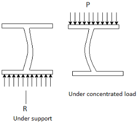
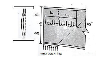
For safety against web buckling. The resisting e shall be greater than the reaction or the concentrated load. It will be assumed that the reaction concentrated load is dispersed into the web at 45" as shown in the Fig.
Let Resisting force F
Thickness of web = t
Design compressive stress in web =fcd
Width of bearing plate= b1
Width of dispersion = n1

For concentrated loads, the dispersion is on both sides and the resisting force can be expressed as, Fwb = [(b₁ +2 n₁) tw fcd] ≥ Concentrated load, P
The design compressive stress fd is calculated based on an effective slenderness ratio of 
Where,
d = clear depth of web between the flanges
Ry = radius of gyration about y-y axis and is expressed as,


Design compressive stress in web, fcd for the above slenderness ratio is obtained from curve, C (Buckling class C) (Table 9c, pg 42)
Q12) What is Bearing Strength?
A12)
The design bearing strength of a bolt on any plate Vdpb as governed by bearing is given by

Where
Vnpb= nominal bearing strength of a bolt

Where
Kb is smaller of e/3do, p/3do-0.25 or 1.0
The bearing resistance (in the direction normal to the slots in slotted holes) of bolts in holes other than standard clearance holes may be reduced by multiplying the bearing resistance obtained as above
Q13) Explain Web Crippling?
A13)
Web crippling causes local crushing failure of web due to large bearing stresses under reactions at supports or concentrated loads. This occurs due to stress concentration because of the bottle neck condition at the junction between flanges and web. It is due to the large localized bearing stress caused by the transfer of compression from relatively wide flange to narrow and thin web. Web crippling is the crushing failure of the metal at the junction of flange and web. Web crippling causes local buckling of web at the junction of web and flange.
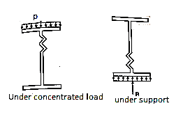
For safety against web crippling, the resisting force shall be greater than the reaction or the concentrated load. It will be assumed that the reaction or concentrated load is dispersed into the web with a slope of 1 in 2.5 as shown in the Fig.
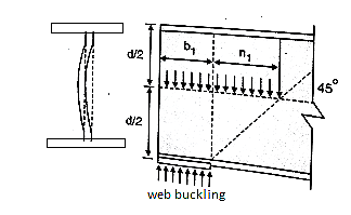
Let Resisting force = Fwc
Thickness of web = tw
Yield stress in web = fyw
Width of bearing plate = b₁
Width of dispersion = n₂

For concentrated loads, the dispersion is on both sides and the resisting force can be expressed as,

Q14) What is mean by Deflection?
A14)
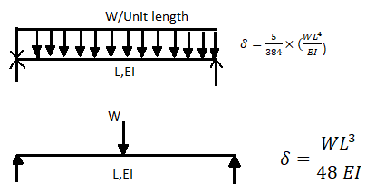
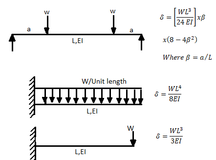
A beam may have adequate strength in flexure and shear and can be unsuitable if it deflects excessively under the service loads. Excessive deflection causes problems in the functioning of the structure. It can harm floor finishes, cause cracks in partitions and excessive vibrations in industrial buildings and pending of water in roofs. Cl.5.6.1, 5.6.1.1 and Table 6 gives relevant specifications with respect to deflection.
The beam size may have to be taken based on deflection, if the spans and loadings are large. Typical maximum deflection formulae for simple loadings are given below:
Q15) Explain Design Procedure of Rolled Beams, Built‐Up Beams (Plated Beams)?
A15)
Design procedure
1) maximum shear force
2) maximum bending moment
M= WL/4
3) selection of cross section (using yielding criteria)
Zp required = 
4) classification of section

5) Design shear strength

6) Design bending strength


7) Checks
- Web buckling

B. Web crippling

C. Deflection limits


Q16) A simply supported beam of effective span 4 m carries a factored point load of 350 kN at mid span. The section is laterally supported throughout the span. Design the cross section using I section.
A16)
- Maximum shear force
V= reaction = W/2 = 1575 kN
2. maximum bending moment
M= WL/4= 350 kn-m
3. selection of cross section (using yielding criteria)
Zp required = 

Select an ISLB 500@75kg/m (using annex H Is 800-2007)
Sectional properties d=500 mm, Izz= 38549 x 1064 mm^4
Zp= 1773.7x 10^3 mm^3 > Zp required
Ze= 1545.2 X 10^3 mm^3
4. classification of section


5. Design shear strength


6. Design bending strength


7. Checks
- Web buckling

At a concentrated load W


Buckling class C
From table 9© IS 800-2007 and fy= 250 Mpa
Kl/r | Fcd |
130 | 74.3 |
131.78 | ? |
140 | 66.2 |
Interpolation
Fcd= 72.85 N/mm^2
At concentrated point load


At reaction R


B. Web crippling


C. Deflection limits
Working load = 350/1.5 = 233.33kN


Provide an ISLB 500@ 75 kg/m beam
Q17) What is Purlins?
A17)
Purlins are horizontal beams which are used for structural guide in buildings. Most commonly, purlins are primary additives of roof structures. Roof purlins are supported both with the aid of using rafters or constructing partitions and the roof deck is laid over the purlins. As a result, they have a tendency to be used for large-scale structures
Purlins are horizontal beams which can be used for structural assist in buildings. Most commonly, purlins are important additives of roof structures. Roof purlins are supported both through rafters or constructing partitions and the roof deck is laid over the purlins.
Traditional wooden framing consists of 3 primary purlin types; the not unusual place purlin, the purlin plate and the essential purlin. Purlins may be manufactured from some of one-of-a-kind substances and are to be had in some of one-of-a-kind types:
C purlins: The form of those varieties of purlins is that of a square 'C'. C purlins are used as purlins over partitions, rafters, ground joists and studs for partitions.
Z purlins: Z purlins resemble the alphabet Z and also are known as Zed Purlins. This form enables the purlins to overlap joint and is more potent and studier than the C purlins.
As a result, they have a tendency to be used for large-scale structures.
RHS purlins: For roofs wherein the assist shape is seen as soon as the development is complete, RHS purlins can be used (square hole section). These purlins are essentially hole, square tubes, with welded ends so there's no metallic bar corrosion, harm or seepage.
Purlins are to be had in type of substances relying on budget, structural and aesthetic requirements. The maximum conventional fabric for purlins is wood. However metallic roof purlins and galvanized purlins can provide advantages of durability, price and structural strength. Cold fashioned metallic and the recent rolled metallic techniques may be used to create the specified shapes from the metallic sheets.
Principal purlin Principal purlins in timber construction, additionally called "foremost purlins" and "aspect purlins," are supported through foremost rafters and aid not unusual place rafters in what's referred to as a "double roof" (a roof framed with a layer of foremost rafters and a layer of not unusual place rafters).
Principal purlins are similarly categorized through how they connect with the foremost rafters: "via purlins" by skip over the top; "butt purlins" ten into the edges of the foremost rafters; and "clasped purlins," of which best one anciently U.S. Instance is known, [citation needed]) are captured through a collar beam. Through purlins are similarly classified as “trenched,” “back,” or “clasped;” butt purlins are categorized as “threaded,” “tanned,” and/or [clarification needed] “staggered
Q18) What is Beam Bearing Plates?
A18)
A bearing plate takes the response of a metal beam and distributes that pressure over a bigger region this is product of a cloth that isn't as sturdy as metal.
The motion is largely similar to a footing that distributes a big load to softer soil
A Bearing plate takes the response of a metal beam and distributes that pressure over a bigger location this is made from a cloth that isn't always as sturdy as metal.
The movement is largely similar to a footing that distributes a massive load to softer soil.
The bearing plate is essential to keep away from crushing of the weaker fabric and to distribute the response pressure over an enough period of beam to save you net yielding or crippling
Q19) What is Effect of Holes in Beam?
A19)
Also, the impact of the round hollow diameter at the lateral buckling load decreases with the lower of hollow diameter.
Namely, while the hollow region is unchanged, the impact of the holes close to clamped side at the essential buckling load decreases because the beam period will increase and hollow diameter decreases
Holes and notches in beams lessen the powerful place to be had to face up to shear and bending second and ought to be taken seriously.
In the case of massive openings, it's far vital to update the misplaced place with the aid of using including plates or stiffeners within side the area of the hollow or the notch
Q20) What is Plate Girder?
A20)
A plate girder is a metal beam this is broadly utilized in bridge production. Depending at the layout necessities and as according to the character of the structure; steel thicknesses for internet, flanges, stiffness, and many others are decided.
The use of the right cloth (metal) having the desired electricity and doing the welding are the 2majorelements to be attended to while growing the plate girder.
A plate girder is used while we want deeper sections having better stiffness to deliver heavy hundreds.
Further, there may be an obstacle in producing a hot-rolled phase while the intensity of the phase is increased. Therefore, we must use built-up sections which could deliver big bending moments and shear forces.
Types of Plate Girders
There may be exclusive classifications relying at the requirements used or relying on the character of the manufacturing of the girders.
There varieties of plate girders.
1. Reverted Plate Girder
2. Welded Plate Girder
Reverted Plate Girder
It is an aggregate of flanges, internet, and different vital stiffness. There are related via way of means of a mechanical method, revert, and plates aren't welded collectively.
- Generally, 90% of the shear is carried via way of means of the internet.
- Connection of the internet and the flange is stabilized via way of means of the angel sections reverted to the flange. Reverts want to be designed for the horizontal shear.
- The reverts that make the relationship among the internet and flange angles want to be designed for horizontal shear and vertical hundreds that carried out to the flange after they switch to the internet.
- Angle sections are used as internet stiffness in revert girders.
Welded Plate Girders
Welded plate girders are maximum broadly utilized in production because of the convenience of manufacturing and its miles a far extra green sort of girder.
These sections are specifically utilized in bridge production. The plate girder bridge could be very stiff and it is able to retain very excessive hundred seven as resisting the lateral movements. This movement may be found within side the railway bridges. Further, they may be used to increase the field kind girders.
There are empirical or approximation strategies to decide the general peak of the plate girder and thickness of the flange and internet.
Components of Plate Girders
Mainly there are 5additives in a girder. The meeting of that 5-thing is the entire girder. The basic requirement is to make an “I” girder having very excessive bending and shear stiffens similarly to the alternative nearby buckling resistances.
- Web Plate
- Flange
- Stiffeners (bearing, longitudinal, and intermediate)
- Splices for flange and internet
- End Connection
Web Plate
The vertical plate of the girder is called the internet plate.
Its thickness is primarily based totally at the layout necessities and the peak can also be determined primarily based totally at the web page condition and as according to the hundreds carried out at the internet.
The internet typically includes the carried-out hundreds at the flange as shear forces. The impact of the internet isn't always usually taken into consideration while the layout for the bending.
The internet is at risk of buckling while thinner and better boom while the hundreds are carried out. Therefore, exclusive varieties of stiffness so as to be discussing on this article, are welded to the internet have its electricity.
Flange
There isn't any distinctiveness aside from using a separate plate for the flange. The flange plate could be welded or related via way of means of different method as mentioned beneath Neath exclusive varieties of plate girders.
Not like rolled sections, we connect the internet and the flange collectively to shape the plate girder.
The flange is layout to hold the bending movement and stiffener or extra plate are furnished as according to the layout necessities.
Stiffeners
Stiffeners are furnished to enhance structural potential heading off the nearby buckling failures. In addition, they may be used to hold the hundreds carried out to the beam till it allotted into the beam.
The following varieties of stiffeners can be found in those varieties of metal elements.
- Bearing stiffeners
- Longitudinal stiffeners
- Intermediate stiffeners
The bearing stiffeners are furnished at assist to distribute the assist response to the internet with none buckling failures. There are jacking stiffness except the bearing stiffeners for installations functions as indicated within side the following figure.
Steel plates welded within side the longitudinal and the transverse instructions also are used to reinforce the internet.
The vertical or the transverse stiffeners may be typically found in maximum of the metal beams that deliver heavy hundreds.
Splices for Flange and Web
It is the splice connection of the internet and the flange of the girder.
When the duration of the girder is less than the span, we must have a splice connection.
This is a second and shear shifting joint which gives beam continuation.
End Connection
End connection is the maximum tough a part of the structural detailing of a metal beam.
When there is continuation or if we are assisting the girder to a few assists, the relationship desires to be designed accordingly.
However, maximum of the time, plate girders are saved as definitely supported on the stop assist. In such situations, we must offer the stiffeners on the stop connection.
A comparable lay out system is followed while designing the endplates and the stiffener furnished vertically connecting the internet and the flange.
Application of Plate Girders
Plate girders are broadly used as assisting systems in exclusive regions. The following regions may be highlighted as key regions of use.
Bridge production
Plate girders are specifically utilized in railway and avenue bridges. Mostly the antique railway bridges may be highlighted as plate girder bridges.
In addition, field girder bridges, beam bridges, navy girder composite bridges, and half – thru plate girder bridges are taken into consideration because it uses.
- Ships
- Gantry beams
- Oil and fuel line platforms
- Load testing
- Cranes
- Lifting systems
Advantages of Plate Girder
- They may be used to hold heavy hundreds
- Speed production
- Grater balance
- High resistance to fatigue failures
- Easy to assemble while as compared with truss kind bridges
- Easy for maintenance
Disadvantages of Plate Girder
- They cannot be used to assist big spans
- Less architectural appearance
- A bit tough to deal within the course of the placement
- Production will be finished strictly according with the layout.
The articles have been written on Steel Beam Design as according to BS 5950 and Steel Beam Design Worked Example [Universal Beam] could be referred for extra facts on metal beam designs.
Q21) Explain Gantry Girder?
A21)
The gantry girders are girders which helps the hundreds which might be transmitted via the journeying wheels of the crane. The crane girder spans from column to column, this typically do now no longer have any lateral help on the intermediate factors excepting whilst a walkway is shaped on the pinnacle of the girder.
Overhead journeying cranes are utilized in business homes to raise and delivery heavy jobs, machines, and so on, from one region to another.
The crane can be a manually (hand) operated overhead travelling crane (M.O.T.) or an electrically operated overhead travelling crane (E.O.T.). A standard association of a crane gadget is proven below. Usually, the crane includes a bridge made from truss girders.
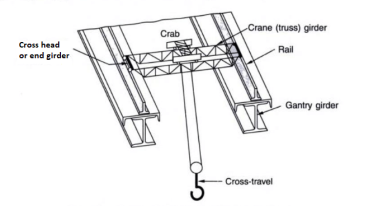
The bridge is called a crane bridge, crane girder, or crab girder. It spans the bay of the store and actions in a longitudinal direction. To facilitate movement, wheels are connected to the ends of crane girders. These wheels pass over rails positioned centrally over the girders that are known as gantry or crane gantry girders. These girders are designed as laterally unsupported beams till the compression flange is laterally supported with the aid of using both a catwalk or with the aid of using a further member. Show under fig. The front view and pinnacle view of the everyday association of a crane girder, gantry girder, and column in a workshop.
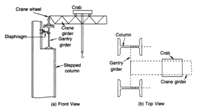
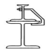
A trolley (crab) with wheels and a suspended hook is located over the crane bridge and this association can flow within side the transverse direction. However, it needs to be stated that the 2 actions of the crane, the longitudinal and the transverse cannot be had simultaneously. Bolted clamps or hook bolts are, used to maintain the rails in position.
Types of Loads on Gantry Gutter:
1) Vertical Loads on Gantry Gutter
2) Lateral Loads on Gantry Gutter.
3) Longitudinal Loads on Gantry Gutter
4) Impact Loads on Gantry Gutter.
- Vertical Loads on Gantry Gutter-
A vertical load appearing over the gantry girder is the response from the crane girder and includes the self-weight of the crane, self-weight of the crab, and the crane capacity (the most load that may be hoisted). To calculate the response the most wheel load is computed. It happens whilst the crab is nearest to the gantry girder. In addition to the response from a crane girder, the self-weight of the rail needs to additionally be considered.
2. Lateral Loads on Gantry Gutter-
Lateral forces on crane girders can be resulting from the (a) Thrust because of the unexpected preventing of the crab and cargo whilst traversing the crab girders (b) Crab dragging weights throughout the store floor. The foregoing instances cannot arise simultaneously.
In (a) As with the longitudinal gantry girders, the frictional resistance of the rail is transferred into the crab girders and from them into the crosshead girders, thence, as factor hundreds thru the principle wheels, into the pinnacle or compression flanges of the gantry girders. The positions of the principle wheels whilst most lateral bending and shear take area at the gantry girder may be similar to the ones whilst most vertical bending second and shear happens.
(b) The crane is regularly requisitioned to tug weights throughout the store floor. If the weight is extraordinarily massive, it's also hooked up on kind of long-established rollers, in all likelihood jogging on a wood plank track. The lateral thrust and pull at the compressive flanges of the gantry girders then grow to be a count number of conjectures. The resisting forces are, firstly, the friction of the principle wheel treads upon the gantry rails and, secondly, the forces supplied through the flanges of the principle wheels bearing in opposition to the gantry rails. The lateral thrust is thought to behave within side the aircraft of the middle of gravity of the top flange.
Acting because it does on the rail level, it has genuinely a lever arm generating torque. This small lever arm and, therefore, the torque are neglected. No assistance is assumed to be afforded through the decrease or tensile flange in resisting lateral thrust. However, need to this assist be considered, then the torque because of the thrust elevated through the space from the road of movement of the thrust to the N.A. (n on this case)—need to additionally be taken into consideration.
3. Longitudinal Loads on Gantry Gutter-
Longitudinal masses are triggered because of the preventing or beginning of the crane girders and bring a thrust alongside the rails. The biggest of those, specifically in quick-appearing electric powered overhead journeying cranes, is because of the unexpected software of the brakes.
The frictional resistance to the sliding of the locked wheels upon the rails is furnished with the aid of using the crane girder. This detail in flip distributes it among all of the crane column shafts. The lateral and longitudinal thrusts are transferred on the rail level. Therefore, gantry girders also are subjected to bending moments because of those masses.
4. Impact Loads
The stresses produced in gantry girders because of the above hundreds are greater than the ones because of regularly implemented hundreds. This is because of the force’s installation through the surprising software of brakes to the hastily transferring loaded cranes acceleration, retardation, vibration, viable slip of slings, etc.
The steelwork which consists of those quick-appearing cranes have to be heavier than the steelwork which helps slow-transferring cranes. With quick-appearing electric powered overhead traveling (E.O.T) cranes, the stresses within side the gantry girders are produced nearly instantaneously, while with slow-transferring hand-operated cranes, the bending stresses within side the girder are brought about regularly from 0 as much as their most values, because the cranes traverse the girder from the give up in the direction of the center.
Design steps:
1) Determine maximum wheel load
By considering the crab is closet to gantry girder. The vertical reaction of the crane girder is transferred through its two wheels on to the gantry girder.
2) Determine maximum bending moment in the gantry girder.
3) Determine maximum shear force developed between wheel load and dead loads.
4) Determine lateral force on the girder and the maximum bending moments and shear due to these.
5) Selection of section and plastic sectional modulus is determined.

6) Classification of section
Using table 2 of IS 800-2007 both I and channel section is classified
7) Check for moment capacity
- For laterally supported girders

b. For laterally supported girder

8) Check for local moment of flange

9) Check for buckling resistance


10) Check for shear

11) Check for buckling of web
Buckling resistance

12) The girder is checked for bearing if required bearing stiffener are provided
13) Connection of channel to the I section are designed.
14) Check for deflection

15) Check for fatigue strength
16) Design connection of bracket to column