Unit - 3
Regulation and control of canal system
Q1) What is Distributary head regulators and cross regulators?
A1)
- When a distributing or distributary channel takes from another channel which is called as Parent channel, the alignment of these channels at the off take, is required to be designed very carefully.
- The best alignment among all is, when the off taking channel makes zero angle with the parent channel at the initial stage and then separates out along the transition curves. The transition curve must be given to the off taking channel as well as to the parent channel to avoid the accumulation of silt jetty and also to ensure equitable distribution of silts.
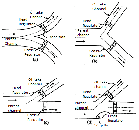
Fig.: Off take alignment
- If the transition curves are not given, both, the parent and the off taking channels may make an angle with the parent channel upstream of off take.
- In case, one wants to keep the parent channel straight both upstream and down-stream of the off take the edge of the channel (not the central line) should be considered, in deciding the angle of off take. The section should not be narrowed down, equally on both the sides.
- An unbalanced off take, results in formation of Silt Jetty the reduction in the sectional area, caused by the formation of Silt-Jetty, will result in scouring of the bed (along the line of deviated current).
Use of Regulators:
- These regulators are provided to control the supply of water, passing down the parent and off taking channels.
- A cross regulator is provided to the parent channel at the downstream of the off-take channel to head up the water level and to enable the off taking channel (or distributary) to draw the required supply of water.
- A distributor head regulator is provided at the head of the off taking channel to control the supply of water which enters into the off taking channel.
Q2) What are the Functions of the Regulator for Parent Channel Cross Regulator?
A2)
- The cross regulator, controls the total regulation of channel system.
- At the time, when the water level is low, in the parent channel, the cross regulator helps to raise the level of water and supplies the full demand of water to the off taking channels
- The cross regulator is used to close down the supplies of water to the downstream, at the time of construction or any type of repair works.
- At the time of conjunction, it allows the extra water to flow from the channel.
- The cross regulator can help to have better transportation facility as the service road can be constructed over the cross regulator (with some extra expenses).
- In various sections these cross regulators can absorb fluctions and can control the possibility of breaches in the tail reaches.
- It helps to control the discharge at an outfall of channel into another channel or a lake.
- In conjunction with falls, they help to central, water surface slope to bring down the channel to regime slope and section.
Q3) What are the Types of Canal regulation works and their functional aspects?
A3)
Head Regulator:
- Definition: In distribution system canals are branched form main canals to this point or junction to this point. Masonry structure constructed is called the head regulator.
Functions of Head Regulator
The main functions of head regulator are as follows:
- It regulates the discharge.
- It diverts proportionate quantity of silt to off taking canal.
- It helps to measure discharge.
- Head regulator consist of rectangular opening with barrels running through bank.
- The upstream abutment is given curved shape while it is normal on downstream side to divert water and silt.
- Functions of the distributary head regulator:
4. It controls the supplies of water, to off taking channel from the parent channel.
5. It controls the entry of silt in the off taking channels.
6. It acts as a meter, to measure the total discharge of water, made to the off taking channels.
7. It can cut off the supplies to the off taking channel. When the supplies water is not required.
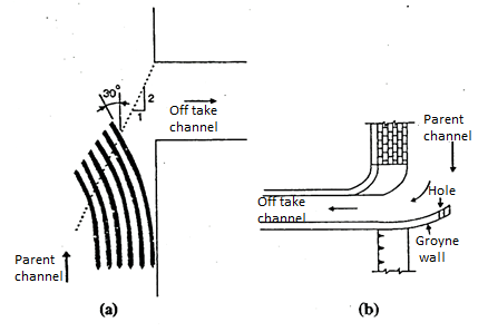
- The entry of silt, in the parent and off taking is one of the basic problems of supplying required quantity of water to the agricultural fields as siltation makes the channels shallow. To control the siltation, along with raised create some other devices also are provided, as per the requirement. They are as follows:
The Kings Vanes
The Gibbs Grayne Wall
Cantilever Skimming Platform
Cross Regulator:
- Definition: The regulator constructed in or across parent canal on downstream of major branch or distribution head regulator is called as cross regulator.
Functions of cross regulator:
The main functions of cross regulator are:
- If controls the flow of water in canal system.
- It raises the water surface elevation in parent canal.
- During repairs it completely stop the flow in lower reaches.
- For cross regulators piers and abutment with grooves are constructed parallel to parent canal and vertical lift gates are fitted into these grooves.
Q4) What is Irrigation outlet?
A4)
- Canal outlets are the structures constructed to allow water into field canals or ditches through which water is supplied to water course.
- It may also be used for measurement of discharge supplied to cultivators. The discharge through an outlet is usually less than 0.085 cumecs. It plays an important role in equal distribution of water.

Fig.: Canal Outlet
Q5) What is the requirement of Irrigation outlet?
A5)
- It should be simple in construction as well as in maintenance.
- It should be cheap, strong and durable.
- It should draw proportionate water according to discharge.
- It should not be easily tampered by cultivator to increase discharge in the water course.
- It should draw proportionate silt.
- It must be simple in design easy for construction and for operation.
- It must not get easily tempered with by the cultivator and if gets tempered should be easily found.
- With a small working head, it must should have maximum efficiency.
- It must collect its own share of the silt, which has been carried by the distributing channel.
- It must be strong, with no moving parts, which need a constant attention and regular maintenance.
- It should give a constant discharge with whatever, functions take place in the distributing channel (This is from cultivator’s side.). From the view point of proper distribution, the outlet should draw the quality of water, which must be proportional to the available water in the distributing channel.
Q6) Explain the non-modular types of outlet?
A6)
- The discharges of these types of outlets the difference in the level of water in the distributing channel and the water course.
The functions of Non-modular outlets:
- They consist of a rectangular or the circular opening, with a pavement (or a submerged pipe). The diameter of these submerged pipe varies between 100 and 250 mm. These pipes are laid down on a light concrete foundation to prevent any leakage through uneven settlement.
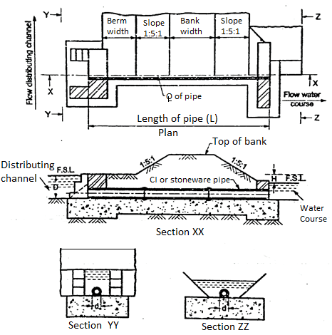
Fig.: Plan of outlet
- These pipes are kept horizontal and at the night angles to the central line of the distributing channel.
- To prevent tempering, these inlets and the exit ends are fixed in a masonry.
- These pipes are usually fixed above the bed of the distributing channel, at a depth of about 225 mm (below the water surface level, in the distributing channels).
- Though, they take their share of silt, the silt conduction can be improved by depressing the upstream end of the pipe and by keeping the pipe horizontal or sloping upwards (at the slope of 1 to 12 to the maximum).
- Because, the silt conduction is controlled by the position of the upstream end of the pipe, it is always placed at the bed of the distributing channel. This position of the pipe, helps to draw its share of silt from the distributing channel.
- The discharge through a pipe outlet can be calculated by equating the difference in the water levels, in distributing channel and the water course; to sum of the loss of head at entry; loss of head due to friction and also due to residual velocity head at exit.
- If we assume H as the difference of water levels in the distributing channel and the water course, we have then
H= … (1)
… (1)
Where, V = Velocity of flow through pipe
L = Length of the pipe
d = Diameter of the pipe
f = the coefficient of the friction
g= The acceleration due to gravity
From the above Equation (1), we have,
V =  … (2)
… (2)
The discharge q through the pipe outlet is given by.
q = AV
Or q = A
Where, A = The cross-section area of pipe.
The above Equation is usually expressed like,
q = CA
Where c = coefficient of discharge, which depends upon, the friction factor, length and size of the pipe outlet.
Using Equation, the value of 'e' can be calculated as,
C=
Advantages of non-modular outlet:
- The discharge of the pipe outlet can be increased by deepening the water course (this is done to lower down, the water surface level in the water course.)
- These outlets can work with very small available heads.
Disadvantages of non-modular outlets:
- The discharge of these outlets depends upon the difference in the water levels i.e., water level in distributing channel and in the water course. So, the discharge varies, as the water level changes.
- Because, the discharge capacity of the outlet is not certain, the equable and the proper distribution of water, through these outlets is not possible. (Water-supply plan is difficult to be developed.)
- The discharge supplied at the head of the distributing channel may not be engaged to feed the tail on the other hands, when the discharge supplied at the head of the distributing channel, is very high, to flood the tail end. (This happens, when the outlets, in the head reaches, take lesser discharges).
Q7) What is Semi modular outlet?
A7)
On the basis of the functioning, the semi-modular outlets can be sub-classified as,
- Pipe Outlet
- Kennedy's Gauge Outlet
- Open Flume Outlet
- Orifice Semi-module outlet
Pipe outlet:
- If any pipe outlet is set in such a manner that its discharge has a free fall into the water course and so, it acts as a semi modular outlet.
- It is one of the oldest and simplest type of semi-modular outlet. The working head 'H' is the difference between the water level in the distributing channel and the centre of the pipe at its exit end. Its discharge is proportional to √H and hence it would be proportional, if it is set at 0.3 times depth, below the water surface, in the distributing channel drain into a natural drain and the pressure of extra quantity of water is taken care of by these weir type escapes.
Kennedy's Gauge Outlet:
- It was evolved by Kennedy in the year 1906 and is one of the oldest types of semi-modular outlet.
- It consists of a cost iron bell, mouthed orifice for entry from the distributing channel. From the orifice the jet of the water, discharges into a chamber to which a vertical vent pipe is connected, which is covered with a cowl pierced with air holes.
- The vent pipe extends above the water-level in the distributing channel and so, it allows the free circulation of the air around the jet.
- These are the conditions, created as if it was discharging in the free atmospheric air and so, it can make the discharge independent of the downstream conditions.
- After crossing the air chamber, the jet enters and expanding pipe, connected to the air chamber and having its entrance diameter, slightly larger than that of the orifice.
- The expanding pipe is generally 3 m long and is made up of cast iron and sheet steel and the end of this pipe, the concrete pipe extension is usually added, through which, the water is discharged into the water course.
- As, the orifice is discharging freely in atmospheric air, its discharge varies as
 where in H0 = Difference between the level of centre of the orifice and the water surface in the distributing channel. Thus, the discharge through the outlet is thus given by,
q =
Where q =discharge (in cumec)
a = Area of orifice (in m2)
H0= Difference between the level of centre of the orifice and the water surface in distributing channel
g = Acceleration due to gravity
C = Coefficient of discharge (As high as 0.97)
Open Fume Outlet:
- It is a smooth weir with a constricted throat to ensure hyper critical velocity i.e. The velocity above the critical value. The length of the throat is such that the controlling section remains within the throat at all the discharges.
- A gradually expending flume is provided, below the throat for ensuring the formation of the hydraulic jump in this portion and to attain the maximum recovery of the head.
- The formation of the hydraulic jump, makes the discharge through the outlet, independent of the water level, in the water course.
- The entire work is built in brick masonry, but the controlling section is provided with a cast iron or steel bed and check plates.
Orifice Semi-Module:
- It consists of an orifice provided with, a gradually expanding flume, on the downstream side. The flow through orifice is hyper-critical which results in the formation of hydraulic jump, in the expanding flume. This makes the discharge through the outlet independent of water level in the water course.
- There are various forms of this outlet. The earliest among them is Crumps adjustable proportional model. (Popularly called as crump's A.P.M.) after the modification of this crump's A.P.M, it has been introduced in the state of Punjab, which is known as the 'Adjustable orifice semi-modular (A.O.S.M.).
- Refer Fig., It indicates the layout of the adjustable orifice semi-module.
- It consists of a cast iron root block a cast iron base plate (or the bed plate) and the check plates on either side, around which the masonry is constructed.
- The roof block is shaped to a lemniscate curve, with a tilt of 1 in 7.5. This makes it sure about the smooth converging flow through the orifice and relatively study discharge coefficient under varying heads.
- This root block is fixed to the check plates by bolts. They can be removed, to adjust the depth of the orifice after the masonry work is dismentated.
Q8) What is Rigid module? Explain its types?
A8)
- A number of rigid modules have been invented some of the modules have some moving parts and some don't have any moving parts.
- The rigid modules having moving parts are generally expensive and also have a danger of frequent breakdown due to floating debris or silt, which clog these moving parts so, the region modules with no moving parts, which do not have the problem of frequent breakdown and which are less in cost are generally selected for the use two common types of rigid modules are described below.
Types of Rigid Modules:
- Gibb's Module
- Khanna's Module
1.Gibb's Module:
- This is one of the most commonly used module which was evolved by A.S. Gibb. The plan and the section of Gibb’s module is shown in the Fig.
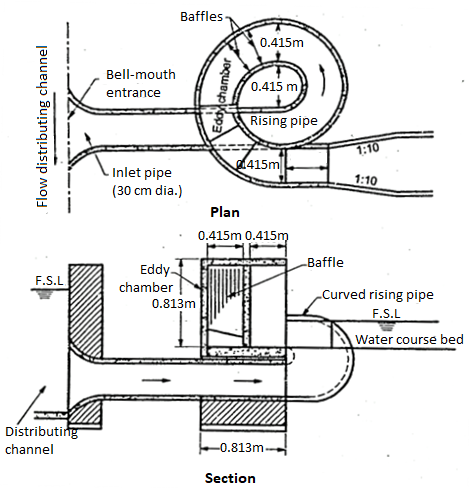
Fig.: Gibb’s Module
- It consists of a bel! mouthed inlet pipe, which is connected to a carve eddy chamber, through a 180° rising spiral pipe.
- The water enters, from the distributing channel into the inlet pipe and it is laid into the eddy cheaper through the rising spiral pipe, in which the free Vortex flow is developed.
- The main characteristics feature of this vortex flow, is that the product of velocity and the radius is constant for all filaments i.e.
V x r= constant
- As the water at the outer circumference of the eddy chamber has a greater radius, it was a low velocity. It makes the rise in the water level.
- Thus, the water surface in the eddy chamber slopes down towards the inner circumference.
- In the eddy chamber a number of baffles are inserted. They are kept suspended from the root of the eddy chamber with their lower ends sloping against the direction of flow at the required height above the bottom.
- As, the head causing flow increases throughout the water banks up at the outer circumference of the eddy chamber and impinges against the baffles, imparting an upward rotational direction of flow to the water, that spins round in the compartment between two successive baffles and finally drops on the oncoming stream of water.
- This is how it can dissipate the excess energy and keeps the discharge constant.
- As per the requirement of discharge and the range of head, the spiral turn may vary from a half or semi-circle turn to one and half complete turns.
- The number of baffles coming into action, depend upon, the variation in head i.e., when more baffles come into action with increase in the head the discharge through the outlet, remains constant.
- Gibb has presented the following equation to explain the discharge through the outlet.
q =
Where in, q= Discharge of the outlet.
r0 = Radius of the outer circumference of the eddy chamber.
r₁ = Radius of the inner circumference of the eddy chamber.
m = (r0/r₁) the ratio of outer to inner circumference.
d₁ = Depth of water at the inner circumference
h0 = Head of water at the inner circumference.
- The above given Equation based on free vortex flow and it holds good only for his standard design where in. m = 2 and (h0/D) = 1/7 where D is the difference of level measured from minimum water level in the distributing channel, to the floor of the eddy chamber.
- Silt conduction of Gibb's module is not to the standard and the outlet is costly.
2.Khanna's Module:
- It is an orifice semi-module with the addition of slopping shoots, which are fixed in the roof block to counteract the increase in the discharge with the rise in the water level in the distributing channel.
- The water from the distributing channel enters the outlet and the outlet and the differential chamber A through the large opening 0 and through the small opening 0' and 0".
- Till the water surface in the distributing channel is at its normal supply level or even below it: the outlets act as an ordinary orifice semi-module.
- When the water surface in the distributing channel rises above its normal supply level the water rises in the chamber A and it enters the first from shoot.
- The backflow from the shoot, impinges on the flow through the outlet and causes dissipation of additional energy of flow and thus, it tends to keep the discharge through the outlet constant.
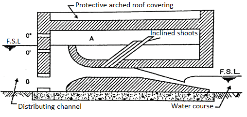
Fig.: Khanna’s module
- Three shoots at a slope of 1 in 2 with their upper ends at the normal supply level in the distributing channel, 150 mm higher than the normal supply level and 300 mm, higher than the normal supply level, were provided in the original design.
- The number of shoots may change as per the requirement.
- The shoots are being provided with a roof, covering, to prevent the tampering.
- Even when the shoot is choked the outlet continuous to function as orifice semi-module.
- With all the above-mentioned advantages these outlets are not commonly used.
Q9) What is River training?
A9)
- 'River training' is a term used to the measures used to stabilize the river channel along a certain alignment with certain cross-sections.
- This is mainly required for the rivers, which flow on fertile pains like Ganga plain, and are known to change their course frequently e.g., River Tista, a tributary river Ganga, has been shifted towards east by more than 150 Kms., in a period of 100 years another tributary of Ganga, i.e., river Kosi, which originates in Nepal Himalayas and flow in Bihar state is also known for its frequent changes in its courses.
Q10) What is Objective and need of River Training?
A10)
- To provide a safe passage to the food discharges, without over flowing to the banks for protection of cultivated and in habited areas.
- To prevent out flanking of a work, like bridges weir or any aqueduct, constructed across the river and to bring the river on the work in non-tortuous approach.
- To protect the river banks from heavy erosion, and also to improve the alignment by stabilizing the river channel.
- To deflect the river away from the bank which it may attack.
- To transport the bed and suspended sediment load with a maximum efficiency.
Q11) Explain the classification of Rivers?
A11)
Rivers can be classified into two types based on the topography of river basin.
- Upper reaches in the hilly region.
- Lower reaches in the alluvial plain.
1. Upper reaches in the hilly region
- River in upper reaches of the hilly region is steep, having swiftness of flow. There is occurrence of landslides and the formation of rapids along their courses in upper reaches of the hilly region.
2. Lower reaches in the alluvial plain
- In such type, rivers flow on alluvia and these rivers are built by rivers themselves. Rivers on alluvial plains can be classified into three basic types:
- Meandering type
- Aggrading type
- Degrading type
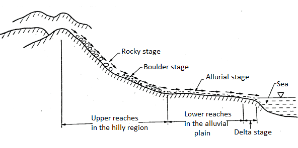
Fig.: Types of river according to topography of river basin
Q12) Explain the classification of River Training works?
A12)
The Classification of River Training Works are as follows:
- High water training
- Low water training
- Mean water training
On the basis of the purpose, the river training work can be classified as,
1.High water training:
- It is main purpose is to dispose off the flood water and to provide protection against any type of damage due to such flooding. It is mainly concerned with the most suitable alignment and the height of marginal embankments for the disposal of floods. It also is connected to take measures for channel improvement for the same purpose. In short, High-water training is training for discharge.
2.Low water training:
- The purpose of such training work is to provide, sufficient depth of water for the inland navigation, during the low water season i.e., during summers for the non-perennial rivers, mainly in south India. This is done by contracting the width of the channel at low water. It is mainly carried out by the help of Groynes. So, the Low water training is training for depth.
3.Mean water training:
- It is mainly carried to have a smooth disposal of bed and suspended sediment load and to maintain the shape of the channel (taking care of the problem of siltation) so, mean water training is Training for sediments.
- Among all the three types of river training works the mean water training i.e., the training for sediments, is most important work. This is because any river training water taken to alter the cross-section and the alignment must be designed which is proper to the stage of river i.e., youthful stage, stage of maturity and the old age at which the maximum movement of sediments takes place during any period under consideration.
- At the youthful, i.e., at the high flow stage, there is a maximum movement of the sediments, but this stage remains for a short period of time.
- There is a little movement of sediments at the old age i.e., at the low stage; but it remains for a very long period of time in short.
- In High stage of flow: The movement is fast but the duration is small.
- In low stage of flow: The duration is long - but the movement is low.
- So, in between these two stages (age of maturity) where in the movement of sediments is higher than the low stage flow and the duration of the process also is higher than high stage flow. So, the middle stage is the most important stage as it has considerable influence on the configuration of the river.
- This is the same stage, where the mean water training is carried out. So, the mean water training forms the basis on which both the high and low water training are planned.
Q13) What is Meandering?
A13)
- Definition: When the river flows on alluvial plains in consecutive curves of reverse order with short straight reaches, then it is termed as meandering river.
- Such type of river is the full and final stage of river development.
- Fig. Shows meandering river.
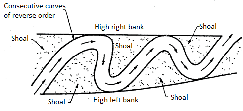
Fig.: Meandering rivers
Q14) What are the different stages of River?
A14)
- There are various stages of a river when it flows from its origin in a mountainous area to a sea.
- There are mainly four stages through which river flows from mountain to sea.
- Four stages of river are as follows:
- Rocky stage or mountainous stage
- Boulder stage
- Trough and alluvial stage
- Deltaic stage
- Fig. Gives the better idea of various stages of river flows from origin to sea of river.
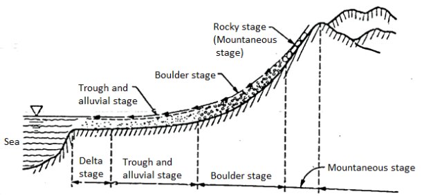
Fig.: Longitudinal section of river showing different stages of river
1. Mountainous stage
- It is also termed as rocky or hilly stage of river.
- It is the first stage of river Started from a mountain and flow through hilly area.
- In such stage, the river flows with very steep slopes and hence velocity of water is ultimate.
Flow characteristics
- Since the river flowing in a steep slope, the velocity is quite high, Due to high velocity the river forms rapids along its course.
- Bed and banks of river are rocky, hence there is very much less erosion and so far river is quite stable. With the flow, most of the silt comes from the catchment caused by soil erosion.
- Note that, the rocky stage of river is an ideal site for the construction of dams.
2. Boulder stage of river
- The second stage of river is boulder stage in which the river flows from rocky stage to the boulder stage as shown in Fig.
- This stage contains the large boulders, gravels and shingles with flows.
- In such stage, the bed slope is very steep and velocity is more but less than the velocity in rocky stage.
Flow characteristics
- In this stage, the river first flows through wide, shallow and interlaced channels and then makes a straight course.
- At the time of floods, the river at this stage carries boulder and shingles downstream the slope. But when floods recede, boulder and shingles get deposited in the river bed.
3. Trough and alluvial stage
- It is the third stage of river in which it flows in zig-zag way as shown in Fig.
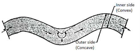
Fig.: River flows in zig-zag way in trough and alluvial stage
- Definition: When the river flows in a zig-zag manner, then it is termed as meandering river.
Flow characteristics
- In this stage, the river flows in zig-zag way or meanders freely in the alluvia! soil from one bank to other.
- The river carries the sediments having same characteristics as like bed and bank.
- In this stage, material is eroded from outer side of the bend and further get deposited on inner side.
- In this stage, the bed slope is not steep but it is flat and velocity becomes low. When flood occurs, then the river spreads over a wide area due to having higher banks than the high flood level of the river.
- In this stage, the behaviour of the river depends upon the silt charge and flood discharge and river can be aggrading, degrading or stable. River training works has to be done in the alluvial stage of floods.
4. Deltaic stage
- Definition: It is the last stage of river prior to go into the sea. When the river split up into a small branch and forms the shape of delta (A), then it is called as deltaic stage.
- In last stage, river split up into small branches and forms a delta.
Flow characteristics
- The bed slope and river velocity are very much decreased because river is not capable to carry its sediments in this stage.
- Due to this, river drop its sediments and split up into channels on both the side of deposited sediments and thus it forms delta shape.
- The channels get silted as the river comes nearer to the sea and water level rises.
- Hence river consists of a large number of small channels in the delta stage in which irrigation work is not possible.
Q15) What are the methods of River Training?
A15)
Methods of River Training are as follows:
- Marginal Embankments or Levees
- Guide Banks or Guide bunds
- Groynes or Spurs
- Cut offs
- Pitching of banks and provision of launching aprons
- Pitched islands
- Other methods like Sills, Closing Dykes, Bandalling.
Q16) Explain Marginal Embankments or levees?
A16)
- They are the earthen constructions which are built to continue the flood waters, within the cross-section available between these Embankments. They help to prevent the spreading of the flood waters.
- The Embankments follow the pattern of the meandering of the river (In the maturity stage, the river does not have enough velocity to erode the obstraction in its flow so it tries to avoid such obstraction by taking a curve.
- This makes the river to move in zig-zag pattern. It is called as Meandering of the river.
- The spacing away from the main channel (i.e., Retirement) of the embankment is controlled by technical and also by human considerations. As the land falling on the river side of the embankments remains unprotected.
- If the marginal embankments are likely to come in contact with high velocity flow, then it is necessary to provide patching protection to the waterside of the embankment. If the embankment is too close to the main river Launching apron also should be provided. (In case of the retired embankments the pitching protection and Launching and Launching apron are normally not required.)
Effects of marginal embankments on the flooded river:
- It helps to increase the velocity of the flood water, to move in the downward direction.
- It helps to increase the surface elevation during floods.
- It helps to increase the velocity of discharge at all the downstream points.
- It helps to reduce the water surface slope of the stream of the upstream leveed portion.
- It helps to rise the velocity and the action of scouring, through the leveled section.
The methodology of the marginal embankments
- When these marginal embankments are constructed, the control the valley storage to either greater or lesser extents. i.e., either the storage capacity is increased or it is decreased by the construction of marginal embankments. This depends upon the spacing's of these embankments from the main river.
- When there is reduction in the storage capacity, the velocity increases; it leads to quicker passage of flood wave higher peak discharge rates and high flood stage. (First three points are explained up to this points).
- The control of flow passage in the leveled reach, will lead to the formation of back-waters and so, the flattening of water surface slope on the upstream of that reach is necessary (This explains the fourth point).
- The increase in the velocity and scouring action, through leveed section depends upon the effects of rising and falling stage of the flood and also on the spacing of the marginal embankments. During the rising stage of the flood, as the discharge and the velocity goes on rising. The sediment carrying capacity of the flow will increase and so the scouring of section will naturally, be in excess of silting or the depositional material in the bed.
- The decrease in the velocity and the scouring action, the siltation will increase and will be more than scouring of the cross section. This is how the effect of flood on the river cross-section, will be the net result of scouring and silting. During the rising and falling stage of the flood.
- As the marginal embankments increase the flood stage and the velocity, they normally, increase the sediment transporting capacity of the stream and so they increase the scouring action. (This clearly depends upon the spacing of the marginal embankments. e.g., If they are away the storage will increase and small rise in high flood level the velocity will be reduced and so there will be reduction in scouring action. If they are closely spaced, the storage will be reduced, the velocity will increase; flood level will increase and the scouring action will be more.)
Advantages of Marginal Embankments:
- They are the only means to prevent the spreading of the flood water over a large area of the flood plains.
- Due to the spreading of flood water, there is always an economic loss of crops, grazing grounds plants etc. It also makes the human beings along with their domestic animals to leave the areas to avoid the danger of floods. Embankments can take of this would be losses.
- The initial cost of these embankments is low (when they are raised subsequently, they become expensive.)
- The construction of embankment is easy and it can be constructed by using local labour and the local material. Its maintenance cost is also less.
- The embankments can be constructed in parts (are must see that the ends are properly protected.)
Disadvantages of Marginal Embankments:
- These embankments' cause rising of the high flood levels.
- It may fail by piping because of the small boring animals like rats, crabs, worms etc. So, these embankments are needed to be supervised very closely during floods and have to protect them when they are found in danger.
- In case of a Breach these is sudden and considerable in flow of water which cases damages to the neighbourhood and by spreading sand over the cultivated fields, it makes them uncultivable. In case of embankment breaches, it may result in almost the total area, protected by the embankment system.
- In case of the areas having no embankments get flooded every year and get a fresh layer of fine soil (brought by the flood water) over the plain region to make it more fertile. e.g., In the flood plains of river Ganga in North India, every year a fresh alluvial soil is brought by the river and is allowed to settle down and to make a fresh-fertile zone along the banks of the river. These soils are called as New alluvial soils or Khaddar soils. In case of embankment, no such formation of fertile soil is possible.
Q17) What is Guide Banks or Guide Bunds?
A17)
- These are the earthen embankments to channelize the flood water of the river. They don't allow the river to change its course during floods.
- In India such types of bunds were designed first by Bell so they are known as Bell's Bunds. Further the designed was modified by Spring and Gates. At present the same design in being used.
- The rivers in the flood plains, spread over a large area during floods (In North India the rivers get flooded twice in a year) and it is very expensive to provide any type of bridge to cross the course of the river.
- By providing a guide bank an artificial gorge section is created for the river in which it can flow without causing abnormally velocities or source and so, the length of the work is considerably reduced (to reduce the cost of construction also) Refer Fig. To observe the main parts of the guide bank, which are as follows:
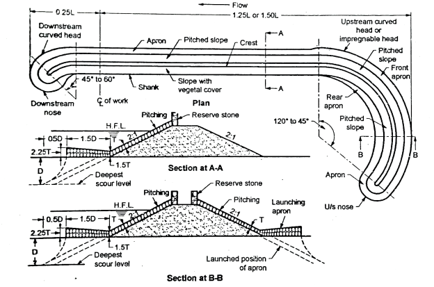
Fig.: Guide bank
- Upstream curved head or Impregnable head.
- Down-stream curved head.
- Shanks and straight portion which joins the two curved head.
- Slope protection and Launching Apron.
- These guide banks are generally provided in pairs which are symmetrical, in plain. In case on the other side, a high stable bank exists, only one bank is provided.
- These guide banks, extending from upstream to downstream, are provided the curved heads, at either side.
- Definition: The upstream curved head called as Impregnable head', is provided to have bell mouthed entry and the downstream is provided to have smooth exit.
- Definition: The remaining portion of the river on either side of the guide bank is covered by the embankments which are known as Approach Banks.
On the basis of their layout, upstream of the work as-
- Divergent guide bank
- Parallel guide bank
- Convergent guide bank
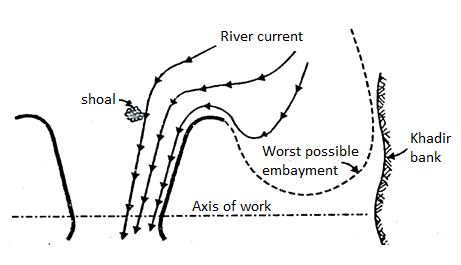
Fig.: a) Divergent type
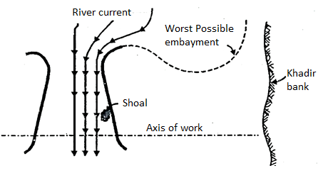
Fig.: b) Convergent type
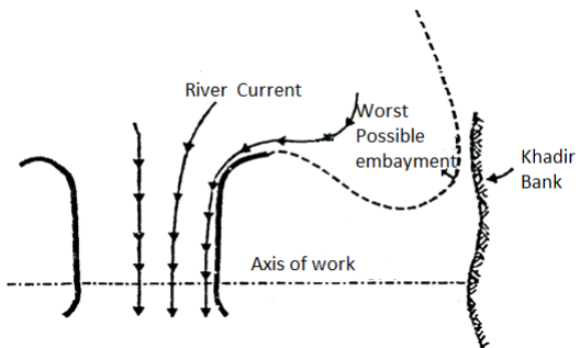
Fig.: c) Parallel type
The divergent guide banks:
- They tend to attract the flow towards them and they are suitable in case of river current oblique to the structure. As shown in Fig.(a) the worst possible embarkment tends to be very close to the approach bank and so it gets less protection.
- These divergent banks have the disadvantage of shoal formation in between them (in case the splay is excessive)
- They get excessive attacks of heavy scour at the upstream head and shoaling all along the bank and them making the end bays ineffective. (Fig.(b))
- To avoid the disadvantages of both divergent and convergent banks, in most of the cases the parallel guide banks. (Fig. (c) are used unless the due to local condition either of these only are suitable.)
Q18) What is Groynes or Spurs?
A18)
- These are the structures, constructed, transverse to the river flow. It extends from the bank into the river.
- The grayness may be aligned perpendicular to the bank line or at an angle pointing up or dam stream.
- The groyens also known as spurs Dikes or transverse dikes. They constitute the most widely used training work of a river.
Function of groups:
The following are the important function of groynes.
- To train the river along the desired course by attracting, deflecting or by repelling the flow in the river.
- To create a slack flow with the objective of silting up the area in the vicinity.
- To protect the river bank by keeping the flow away from it.
- To construct a wide channel for making the river navigable.
Q19) What is Cut offs?
A19)
- Definition: It can be defined as a process by which an alluvial river, flowing along a curve or bends. Abandons a particular bend and establishes its main flow, along a straight and a shorter channel.
- This shorter channel is known as 'cutoff. It happens to a river channel when the distance between two meanders is reduced to such an extent that, during the floods, which the rise in the velocity and also the quantity of flow, the river can take care of this narrow bend and starts flowing in the straight direction.
- Due to reduction in the length of the river channel (no meandering) there is steepening of slope which results in drawdown and erosion upstream of the cut-off and deposition of some of this excess eroded material downstream of the O cutoff. These disturbed conditions continue for some time till the equilibrium is reached.
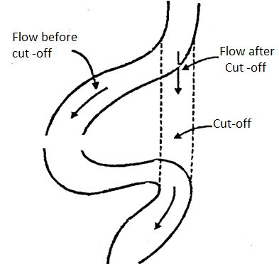
Fig.: Cutoff
- An artificial cutoff may be induced for the purpose of river training, to divert the river from a curved flow which may be creating danger to the valuable land or property or may be to straighten its approach, for easy working.
- For a flow around a bend, the ratio of length of the bend to that of the chord is called as the cutoff Ratio. When this ratio exceeds 1.5 to 2.5 a natural cutoff may take place and so that artificial cutoff is induced which the cutoff ratio falls in this range only i.e., 1.5 to 2.5.
- For artificial cutoff only a pilot channel (or a pilot cut) is excavated. Which gradually enlarges to the required cross section by the flood-water and the old (original) curved channel is abandoned.
- The alignment of the pilot channel should be such that both the ends the cut is tangential to the main direction of river flow.
- This alignment of the pilot channel should be made on a slight curve to promote speedy developments.
- The entrance to the pilot channel should be made bell mouthed but at the downstream end of the pilot channel, this bell mounting is not necessary because as the cut develops at the lower end and it works progressively towards upstream.
- If these cuts are likely to be developed by scour, because of too low velocity (or high resistance of the bed and bank material), they must be excavated to the main river section.
- Like the natural cutoffs, the artificial cutoffs also cause disturbance of river regime both in up and downstream, till the readjustment is made.
Q20) What is Pitched Island?
A20)
- It is an artificially constructed island in a river bed.
- It consists of a sand-core, which is protected by stone pitching (revetment) on all the sides of the island.
- A launching or falling apron, is provided around the island to provide protection to the toe and the slopes.
- Such island causes redistribution of velocity and tractive force. This tractive force near the island, starts to increase very rapidly, after the island is constructed.
- It results into the formation of deep scour, around the island and slowly draws the main current towards itself and finally hold it permanently.
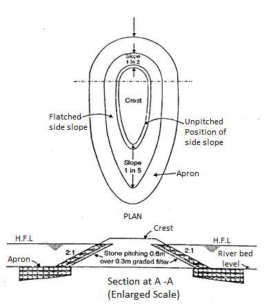
Fig.: Pitched Island
- Thus, the pitched island, may be utilized to attract the main current and to reduce the unrequired concentration on the banks of the river.
- It also may be utilized to maintain the approach to same engineering work in the desired direction.
- Because, a deep scour appears around the pitch island, which creates heavy concentration of flow in its vicinity a stone pitching and a launching apron is designed for maximum scour, under the worst conditions. (They are taken as 2R, where in R=Lacey's regime scours depth)
- They work as the guide bank. The length as well as the shape of such artificial island is designed with a help of model tests.
- The success of such pitch island depends, mainly on the extent of scour around the island e.g., In case of a wide and shallow rivers, as the obstruction caused by such island is less the scour will not get developed around the island readily.
- In case of flashy rivers, there is no enough time for the development of scour-around the island (and even if it gets developed during the rising stage, it may get filled up during the filling stage of the river)
- So, in such cases, pitch islands may not get enough success to get the desired effects.
Q21) What are the types of headwork?
A21)
- The canal head works can be categorized into the subsequent types.
- Storage head works
- Diversion head works
- Storage head works include a dam built throughout the river to create a reservoir wherein water is saved throughout the duration of extra go with the drift with inside the river. From the reservoir, water is furnished to the canal in required amount as according to demand. Thus, garage head works shops water further to the diversion into the canal.
- Diversion head works serve to elevate the water degree withinside the river and divert the specified amount into the canal. The diverse functions served through diversion head works are as follows:
- They increase the water degree with inside the river in order that the commanded region is increased.
- They regulate the delivery of water into the canal.
- They control the access of silt into the canal.
- They will offer a few garages of water for a brief duration.
- They reduce the fluctuations with inside the degree deliver withinside the river.
Types of diversion head works:
- The diversion head works can be categorized into the subsequent types:
- Temporary diversion headworks
- Permanent diversion headworks
- Temporary diversion headworks include a spur or bund built throughout the river to elevate the water degree withinside the river and divert it into the canal. These bunds can be required to be built each 12 months after the floods, due to the fact they'll be broken through the floods.
- Permanent diversion headworks includes an everlasting shape consisting of weir or barrage built throughout the river to elevate the water degree withinside the river and divert it into the canal. Most of the diversion headworks for critical canal machine in our us of a are everlasting diversion headworks and the identical are defined withinside the following sections.
Q22) What are the component parts of diversion headwork?
A22)
A diversion head work consists of following component:
- Weir (barrage)
- Under sluice
- Fish ladder
- Divide wall
- Canal head regulator
- Silt excluder
- Guide bank
- Marginal bunds
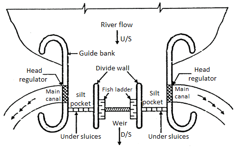
Fig.: Layout of Diversion headwork
The various components and their functions of head work are explained in following section.
Weir and Barrage:
- A structure constructed across river to raise water so as to divert this raise water into canal and this raising of water is mostly done by the crest wall constructed across river and very small part or nil part is by shutter sometimes if provided on its top is called as weir and when (most water stored) storing of water is done by gates or shutters and small part or nil part of water is by the raised crest then such structure constructed is known as barrage.
- In weir affluxed caused is more during high floods while in barrages afflux is nil or minimum 2s flow of water is controlled by shutters during floods gates are opened and thus afflux is controlled.
Under Sluice:
- Under sluice are the opening provided in the body of weir at low level.
- These are located at same side from which canal is taking off. The crest of under sluice is kept lower than crest of weir due to which water is attracted towards it and thus ensure easy diversion into canal.
Functions of under sluice:
- It controls entry of silt into canal.
- It lowers the HFL
- It helps in passing low river floods without lifting shutters.
- It helps to pass silt on downstream side of weir.
- Whenever silt is to remove the gates of head regulator are closed and of sluices are opened through these sluices the silt which is deposited is removed and it goes on downstream side when all silt is removed sluice gates are closed and regulator gates are opened.
Divide Wall:
- It is wall constructed between under sluices and the weir at right angle to the axis of the weir to divide the river channel.
Functions of divide wall:
- It separates the under sluices from weir.
- It also helps in reducing velocity of flow near the head regulator due to which silt is deposited and clear water passes into canal.
- It prevents vortices means flow in circular motion.
Fish Ladder:
- Definition: It is passage provided adjacent to divide wall for the movement of fish from upstream to downstream and vice versa is called fish ladder.
- It has been observed that fish moves from cold water to warm water and in monsoon they again move towards upstream or downstream of the work.
- These are provided with various fashion like sluice type in which the baffle wall is in zig zag way over flow type in which V notches are provided in staggered arrangement etc.
Silt Excluder:
- It is structure in the under sluices to pass water containing silt on downstream through under sluices so that only clear water enters into the head regulator.
- These are parallel to the axis of head regulator, Silt excluder prevents the entry of silt into the canal.
- It consists of number of small tunnels with their roof slab at same level. The crest of the head regulator and the tunnels are of different lengths.
Guide Bank:
- Guide banks are provided on either side of diversion head work in alluvial soil to prevent river from out flanking the work.
- The main object of guide banks are:
- It prevents oblique approach to the head regulator.
- It protects regulator from river attack.
- It increases maximum discharge at all point.
- It prevents out flanking of structure.
- It creates reasonable water way for a weir.
Marginal Embankment:
- Marginal embankment is provided on either bank of river upstream of diversion head work to protect the land and property which is likely to be submerged during flood.
Marginal embankment helps in-
- It increases the intensity of flood.
- It increases bed level of the river by silting.
- It protects land and property which is likely to be submerged.
Head regulator:
- It regulates discharge.
Q23) Explain Failure of hydraulic structure founded on permeable foundation?
A23)
- The design of hydraulic structure on permeable foundation by Bligh theory is accepted theory from 1910 onwards and most the design of hydraulic structure on permeable foundation were based on the Bligh theory.
- Later on, some of the structure becomes troublesome and some of them are failed and other remained stable.
- In 1926-27, the siphon on Upper Chenab Canal was designed based on Bligh's theory and further this structure started giving undetermining problems and then investigation of this problem or trouble raised carried out by Dr. A. N. Khosla by inserting pipes on the floors of siphon on Upper Chenab Canal.
- After investigation, it is clearly observed that the actual uplift pressure for which the horizontal floor designed was quite different from the uplift pressure computed according to Bligh's theory.
- This investigation done by Dr. A. N. Khosla finally ultimately made the following conclusions.
- The outer faces of the end of cut-off or sheet piles are found to be effective rather than the inner faces and the horizontal length of the floor.
- Smaller lengths of intermediate sheet piles than the outer piles are found to be ineffective expect for local distribution of uplift pressure.
- When the hydraulic gradient at the d/s exit is more than that of the critical gradient for that particular soil, then there is piping of the floor starts from the tail end. Due to this undetermining or piping problem, some soil particles move along with the flow of water and this further leads to start the progressive degradation of the sub-soil. Due to the progressive degradation, there is the formation of cavities below the floor causing the ultimate failure.
- It is more essential to provide a reasonably deep vertical cut-off or sheet pile at the downstream end of the floor to avoid piping problem or undetermining.
- Dr. A. N. Khosla carried out further research to find the ultimate and complete solution of sub-surface flow in case of permeable foundation results of Khosla’s theory is given in Central Board of Irrigation and Power (CBIP) in the publication no. 12 under the sector of the "Design of weirs on permeable foundation".
- Dr. A. N. Khosla determined the flow pattern below the impervious base of floor of weir structure on permeable foundation. He started with the potential flow theory and suggested the best solution of Laplace's equation for various configuration of a floors.
From the flow pattern, the distribution of uplift pressure on the base of the hydraulic structure like weir and, also found the exit gradient.
7. Dr. A. N. Khosla found out the best solution for various cases.
- Solution for a horizontal imperious floor without providing the sheet piles.
- Solution for a hydraulic structure with a composite profile.
- Method of independent variables.
Q24) Explain Principles of Design of Bligh’s theory?
A24)
- According Bligh's theory, in case of permeable foundation; water percolates into foundation of the structure between the profile of the base of weir and sub-soil.
Definition: The length of the seepage path creeps into the foundation is called as creep length (L).
2. According to Bligh, there is no distinction between the creep in the horizontal direction below the floor and in the vertical direction along the faces of the profile.
3. Loss of head per unit length of creep is constant throughout the path of seepage.
4. If H= total loss of head and L= Total creep length of seepage, then loss of head per unit length is equal to H/L.
5. Fig. Shows a weir with a horizontal floor of length L. Weir is subjected to a seepage head H.
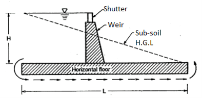
Fig.: Bligh’s creep theory for permeable foundation
- So as the rise the percolation path of water's cut-off or sheet piles are provided as shown in Fig.
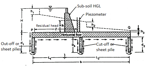
Fig.: Seepage head for simple weir structure
- According to Bligh, there is horizontal and vertical creep path of percolation in the same sense.
- Total creep length (L) = (2d1+L1 +2d3+ L2 +2d2).
- Where d1, d2 and d3 are the depths of the u/s, d/s and intermediate cut off or sheet piles respectively L1 and L2 are the length of u/s and d/s floors.
6. Sub-soil hydraulic gradient (i) is given by the expression as, follows:


Figs. Shows the sub-soil hydraulic gradient (i).
7. As the water moves in a vertical path, there is loss taken place in the vertical plane at the same section and this loss is proportional to the length of the vertical path.
∴For cut-off d1Loss of head =  and it takes place in its plane
For cut-off d2, loss of head = 
For cut-off d3, loss of head = 
Residual head (h) =
=
8. Bligh also suggest the design criteria for the safety of a weir against:
- Piping failure
- Uplift failure
Piping failure:
- The weir structure is safe against piping if the percolating seepage water retains negligible upward pressure when it comes out at the d/s end of the weir.
- Hence the path of percolation should be kept sufficiently long so as the provide safe sub-soil hydraulic gradient (i).
∴For safe design:
 …. (1)
Where C is Bligh's creep coefficient.
Table gives Bligh's creep coefficient.
Sr. No | Soil type | Value of C (creep coefficient) | Safe hydraulic gradient =1/C |
1 | Silt and mud | 18 | 1/18 |
2 | Fine micaceous sand | 15 | 1/15 |
3 | Coarse grained sand | 12 | 1/12 |
4 | Boulder and gravel mixed sand | 5 to9 | 1/5 to 1/9 |
5 | Gravel | 5 | 1/5 |
If H = seepage head and L= creep length, then Equation (1) can be given as follows:
 …. (For no piping)
Or L
L=CH … (for limiting case)
In short to have the weir structure is safe against piping failure, the creep length L must be equal to or greater than the product of the creep coefficient (C) and seepage head H.
Uplift pressure:
- Horizontal floor or apron floor should be safe against uplift pressure. Bligh suggested the criteria to have the apron floor safe against uplift pressure Fig. Shows the uplift pressure diagram.
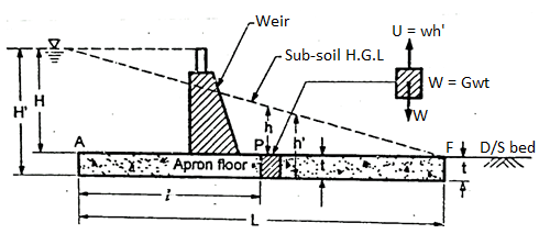
Fig.: a) Simple horizontal floor

Fig.: b) Uplift pressure diagram
- Fig. Shows a simple horizontal floor or apron floor of length L subjected to a seepage head of H.
The residual head (h) = H- 
At any point P, l= Horizontal length from A to P
Upward force U caused by uplift pressure is given by:
U=wh’×1=w(h+t) … (2)
… (2)
Where, t = Thickness of horizontal apron
Downward force W caused by weight of floor material is given by
W= …. (3)
Where  = sp. Gravity of the floor material
For stable condition or equilibrium condition Equations (2) and (3) we get,
U = W
∴wh' =  wt
wt
w (h+t) =  wt ∵ h'=h+t
t ( -1) = h
Generally, a factor of safety of is adopted.
∴t= … (4)
… (4)
- Equation (4) gives the required thickness t of the horizontal apron provided height h of the sub-soil hydraulic gradient above the top surface of the floor is known.
Limitations of Bligh's Theory:
Following are the various limitation of Bligh's theory.
- No differentiation between the vertical creep and horizontal creep. Bligh gives the same importance to both.
- Head loss variation is linear but actual head loss variation is non-linear.
- The effect of varying length of cut-off or sheet piles not considered.
- No distinction is considered between the head loss on outer face and on the inner faces of sheet piles.
- No theoretical or practical method to find the creep coefficient or the safe gradient.
- The exit gradient is not considered.
- Loss of head is considered proportional to the creep length. Actually, it is not correct.
- Necessity of providing end sheet pile not appreciated.
- Bligh theory does not give the approximate results if the horizontal distance between the piles is less than twice their depths.
Q25) Determine exit gradient for the floor shown in fig. Using:
1)Bligh’s theory and
2)Lane’s theory. The values in the fig. Indicate the R.L values in meters. Neglect thickness of cutoffs. Comment on the safety of the floor against piping if Bligh’s and Lane’s coefficient of creep C and C1 are 5 and 3 respectively.
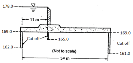
A25)
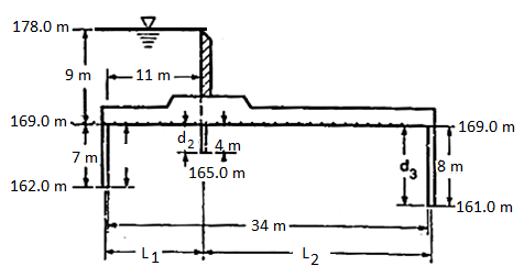
Total length of creep=L= (7×2+4×2+8×2) +34=72m
Bligh’s creep theory
i =H/L=9/72=0.125
Lanes weighted creep theory


 =49.33
Lanes weighted creep theory=H/L=9/49.33=0.182
Provided L=34’

C=5, Bligh’s theory 1)0.125
C1=3 Lanes weighted theory 0.125
∴ It should provide L=0.125
Q26) Explain Khosla’s theory for determination of pressure and exit gradient?
A26)
- Dr. Khosla suggested the theory of independent variables to determine the uplift pressure at the key points for the structure consisting of a combination of a number of elementary forms such as a horizontal floor, three piles, U/S glacis and d/s glacis.
- In the method of independent variable, Dr. Khosla split up a complicated weir or barrage into number of standard simple forms for which the analytical solution is known.
- Uplift pressure is obtained from the basic assumption followed by the corrections.
Assumptions
- The floor has negligible thickness.
- There is only one sheet pile line.
- The floor is horizontal.
- Above assumptions are not satisfied due to an actual profile and hence corrections are applied to the superimposed values of uplift pressure corrections:
- Correction for thickness of floor.
- Correction for slope of the floor.
- Correction for the mutual interference of piles.
Standard simple elementary profile:
- Following are the various standard elementary forms or profiles suggested by Dr. Khosla.
- Standard elementary form (i): A straight horizontal floor having negligible thickness and sheet pile provided at the downstream end as shown in Fig.(a).
- Standard elementary form (ii): A straight horizontal floor having negligible thickness and sheet pile provided at the upstream end as shown in Fig.(b).
- Standard elementary form (iii): a straight horizontal floor having negligible thickness with spect pile provided at some intermediate point as shown in Fig. (c).
- Standard elementary form (iv): A straight horizontal floor having thickness (d) depressed below the bed without sheet pile.
- Above four case of standard elementary form was studied and analysed by Dr. Khosla and his associates and derived the standard equations to determine the uplift pressure at the key points such as junction points of sheet pile and floor, bottom most points of she t piles and bottom corners of depressed floor and exit gradient.
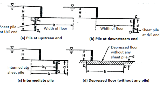
Fig.: Elementary forms of Khosla’s method of independent variables
Uplift pressure (P) for floor with d/s pile:
Refer the Fig.(b)
Uplift pressure at E = PE =  … (1)
… (1)
Uplift pressure at D = PD =  … (2)
… (2)
Equations (1) and (2) are usually written in term of percentages pressure as  and
and 
∴
Where,  =
= 
∴
The values of percentage pressures of  and
and  can also be determined from Khosla's chart as shown in Fig.
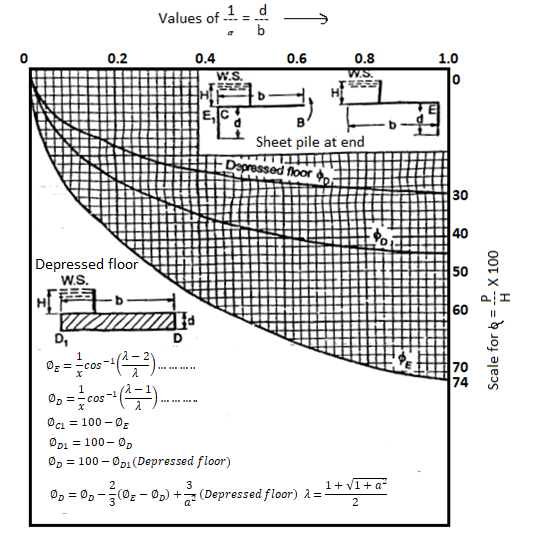
Fig.: Khosla’s Chart
Uplift pressure for floor with U/S sheet pile:
Refer to Fig.(a)
 =
= 
Or 

In same way can be obtained as follows.
 =
= 
Or 

The values of percentage pressures of  and
and  can be determined from the Khosla's chart as shown in Fig.
Exit Gradient:
- The horizontal floor should be safe against piping; hence to make it safe, the exit gradient should be less than the safe gradient for soil.
- For exit gradient for impervious floor with the d/s sheet pile, refer to Fig.
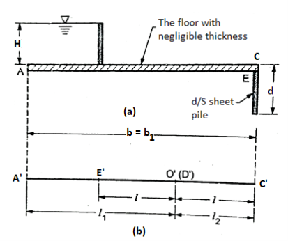
Fig.: Impervious floor with d/s sheet pile
- Fig.(b) shows the floor after transformation uplift pressures at E, D and C are as follow:


Where, λ = 
- Exit gradient is given by the following expression as:
 … (1)
… (1)
- The value of exit gradient GE can be obtained from the known values of b and d after determining
 and ⋋.
 - Khosla's chart as shown in Fig. Can be used for the determination of ⋋and
 from the known values of
  and then substitute these values in Equation (1).
 - Note that the correct curve should be taken for the determination otherwise the value will go wrong.
- Note that if floor is not provided by d/s sheet pile or cut-off, d becomes equal to zero and then the exit gradient becomes infinite which do not occur theoretically in actual practice, resulting the a very high value of exit gradient and due to this piping can occur.
- Hence it is absolutely necessary to provide the vertical sheet pile or cut-off at the d/s end of the floor which p events the piping problem.
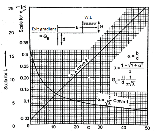
Fig.: Determination of exit gradient
Table shows safe exit gradient for various types of soil.
Sr. No | Soil type | Safe exit gradient (GE) |
1 | Fine sand or silt | 1/6 to 1/7 |
2 | Sand (Coarse) | 1/5 to 1/6 |
3 | Shingle, Gravel | ¼ to 1/5 |
Q27) What is Canal fall? Explain Selection of site of canal fall?
A27)
- It is structure, which has been constructed across a channel, to permit lowering down of its water level and to dissipate the surplus energy passed by the falling water (this extra energy scours the bed and banks of the channel).
Location of Falls:
- When the natural slope of the ground is greater than the designed bed slope of the channel, it is necessary to reduce the differences between these slopes. This is done by providing the vertical falls or drops, in the bed of the channel at the suitable intervals. Following points are necessary to consider, before locating such falls or drops, in the bed of the channels.
- It must be provided at a location where the F.S.L of the channel, out strips the ground level, but before the bed of the channel comes into filling.
- It should be located at such place that there would be no danger of loss of the command area.
- It should be such that below the fall, F.S.L. Of the channel remains below the ground level for 1/2 to 3/4 km, (but, no much more). This will, not result in any loss of command area, so to that extent the area can be irrigated by the water course from an outlet at high level upstream of the fall.
- The location of such fall if is combined with a regulator, or a bridge or any such structure, it becomes economical. i.e., cheap.
- It is necessary to see where in that area, where large number of small falls or small number large falls are economical, with the same conditions of not reducing the command area.
- For a small length of the channel, in upstream and also in the downstream of a fall, there is unbalanced earth work it should be kept minimum. For a larger fall, the quantity of unbalanced earth work will be large in volume so the provision of small number of large falls will result in larger quantity of unbalanced earth work so the reduction in the number of falls, will help to reduce the cost of falls. (This saving is to be balanced against the extra cost of earth work, to determine the relative economy).
Selection of Site for Canal Fall:
Following are the various factors to be considered for selection of site for canal fall:
- So as to achieve the economy of earth work, the site for the fall for main canals and branches from which no direction irrigation is done is preferably selected.
- A fall is preferably provided the site where F.S.L of the canal outstrips the ground level but before the canal bed comes into the filling.
- The site for the fall in case of distributaries from which direct irrigation is done is preferably selected such that the command is not sacrificed in the process of lowering of the water level.
- The site of fall is selected from the consideration of the possibility of combining it with a cross regulator, any other masonry structure of a road bridge. This result gives in better economy and better regulation.
- The site for canal fall should be selected or decided where there can be the combination of various canal regulation work. This combination gives the minimum overall cost.
Q28) What are the types of falls?
A28)
Types of Falls are as follows:
- Ogee fall
- Rapid fall
- Steeped fall
- Notch fall (Trapezoidal)
- Vertical drop type of fall
- Glacis type fall
- Meter or Non-meter fall
- Flumed and full width fall
- Cylinder fall
- Buffle fall or Inglish fall
- Montagu fall
- Sarada fall
- Siphon falls
- Chute fall
- Pipe fall or shaft fall
Ogee Fall:
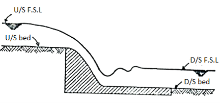
Fig.: Ogee fall
- This type of falls are constructed on Ganga canal. The basic aim of such fall is to get the smooth transition from upstream to the downstream water level; ant to have minimum impact. As shown in Fig., the falls is provided with a gradual convex and concave curve.
- The ogee falls have two short comings.
- Due to heavy drawdown on the upstream side of the fall, the bed and the side erosion is heavy.
- Due to smooth transition, the kinetic energy was fully preserved. It causes erosion of bed and sides i.e., banks of channel, on the downstream side of the fall.
Rapid Falls:
- This type of fall was constructed on western Yamuna canal. The falls were constructed by with bolder boulder facing and had gentle slopes in the range between 1 in 10, to 1 in 20.
- The long glacis assured the formation of hydraulic jump and so, these falls, have a smooth working.
- The construction cost of such falls is very high.

Fig.: Rapid fall
Stepped Falls:
- These falls are modified from the rapid falls i.e. The long glacis of the rapids fall wave converted to the floors in steps in these steeped falls. The cost of the construction of such falls, also is very high.
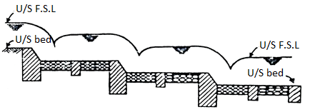
Fig.: Stepped fall
- After the development of such stepped fall, it was found that better dissipation of energy, can be achieved through the vertical impact of falling the jet of water on the floor and so, the vertical falls evolved. However, the earlier types of vertical falls were not well developed and started giving trouble, so they were replaced by Trapezoidal notch falls.
Trapezoidal Notch Fall:
- It was introduced in 1894, by Reid. It consists of a number of trapezoidal notches, in a higher breast wall, across the channel, with a smooth entrance and a flat circular lip projecting downstream from each notch to disperse water.
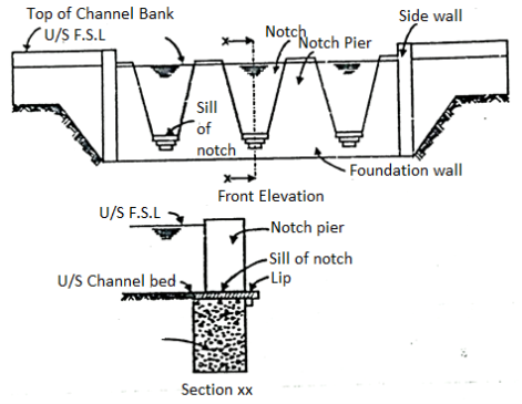
Fig.: Trapezoidal notch fall
- In the fall, the notches were designed to maintain the normal depth of flow in the upstream channel at any two discharge values, the variation at intermediate values being small. So, the depth-discharge relationship of the channel remained almost undisturbed by the introduction of the fall. These types of falls were very popular in India, however, after new types of falls were introduced, the trapezoidal notch falls here become obsolete.
Vertical Drop Type Falls:
- In this, the clear nappe leaving the crest is made to impinge into cistern below. The cistern provides a water cushion and it helps to dissipate the surplus energy of falling jet. In the earlier types of vertical drop type falls, the dimensions of the cistern were decided, arbitrarily, on the basis of the past experience of the designers.
- Then, a grid consisting of bulks of timber spaced few centimeters apart, was provided in the cistern to intercept the falling nappe and thus dissipate its surplus energy. Because of the need of frequent of replacement of the timber grid, this type of falls were abandoned. This type of fall was used in Sharda canal project in Utter Pradesh, it is running very smoothly.
Glacis Type Fall:
- In this type, the hydraulic jump or the standard wave is being used; for the dissipation of energy. Before the introduction of this type of fall in Punjab a flumed fall with straight glacis was introduced, but some serious problems were the functioning that type of fall. One of the serious problems, was that, even after the formation of the hydraulic jump, there was still a considerable extra energy in water.
- Another problem was due to too rapid expansion after the fluming eddies were developed, causing deep scours. So, a lot of researches were carried to eliminate these faults and finally two new types of falls, namely Montague and Inglis were developed. In Montague type of fall, the straight glacis has been replaced by Parabolic glacis community, known as Montague profile. In Inglis type fall straight glacis is provided but at a certain distance from the toe of the glacis, a baffle wall of certain height is provided both of these types at all are designed to hold the hydraulic jump stable, to affect the maximum dissipation of energy.
Meter or Non-Meter Fall:
- Definition: One that can measure the discharge called as Meter fall, and another that cannot measure the discharge of the channel is called as Non-Meter fall.
- If a fall is adopted to measure the discharge of the channel, it must have a broad crest, so that the discharge coefficient is constant, under varying heads.
- Generally, a vertical drop type fall is not suitable as a meter fall due to the formation of partial vacuum under the nappe.
- On the other hands glacis type fall are quite reliable meters, under different working conditions.
Flumed and Full Width Falls:
- Definition: Either the fall is constructed of the fully channel width or it may be contracted. The falls of the second type i.e., contracted falls are known as Flumed falls.
- For such falls, a smooth upstream transition should be provided to avoid turbulence and to maintain the accurate depth discharge relationship.
Cylinder Fall or Well Fall:
- In such type of fall, water of canal is thrown from higher level in a well or cylinder from where it escapes from bottom.
- When water is thrown in a well, the energy is dissipated in the well in turbulence.
- Such type of fall is more suitable for low discharges and they are economical and used at tail escapes of small canals.
- Fig. Shows the cylinder fall or well fall.
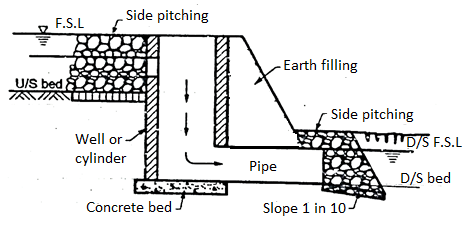
Fig.: Cylindrical fall
Baffle Fall or Inglis Fall:
- In such type of fall, glacis is straight and slopping and downstream floor is provided by baffle wall so as to dissipate the energy.
- Main part of glacis is made in concrete. Curtain walls are provided at toe and heel. Also, stone pitching is done at upstream and downstream end.
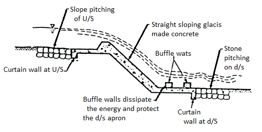
Fig.: Inglis fall
Montagu Fall:
- In such type of fall, when hydraulic jump take place on sloping glacis, then vertical component of velocity is not affected which creates the problem of residual energy below the jump. Therefore, it is much essential to design proper profile of the glacis. Glacis profile should be designed in such way that the maximum horizontal acceleration of fall is imparted to the jet and thus attained the maximum horizontal velocity in any given length of the work.
- Montagu derived analytically the ideal glacis profile as follows:
x = U +y
+y
Where x = Horizontal distance to any point on the profile measured from the crest
y = Vertical distance to any point measured below the crest
U= Initial velocity of water leaving the crest
g = Acceleration due to gravity
- Fig. Shows the Montagu fall.
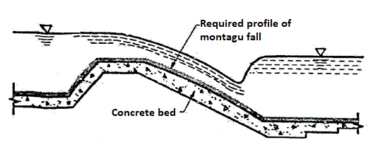
Fig.: Montagu fall
Sarada Fall:
- Design and development of sarda fall was done on a sarda canal system of UP. Sarda canal area consists of thin veneer of sandy-clay which overlies a strata of pure sand. Therefore, a number of falls with small drops should be provided so that minimum depth of cutting can be kept.
- This fall is constructed for the drops varying form 0.9 m to 1.8 m.
- In previous design, the cistern was not depressed below the downstream floors and downstream were not flared and due to this the banks to the downstream of get eroded and therefore various model experiments were carried at the Bahadrabad Research Station and certain recommendation were made.
- Design criteria of sarda fall are based on these.
Q29) Explain the Design of Sarda type of fall?
A29)
The design of Sarda fall consists of the following various components.
- Design of crest
- Length of crest
- Shape of the crest and discharge
2. Design of cistern
3. Design of impervious floor
4. Downstream protection
- Bed protection
- Side protection
- Downstream wings
5. Design of upstream approach
1. Design of crest
It consists of three main design parameters
- Length of crest.
- Shape of the crest and discharge.
- Crest level.
a. Length of crest
- The length of the crest and bed width of the canal is kept equal. Fluming is not done in this type of fall.
- Note that, sometimes.
Length of crest = (bed width + water depth) to anticipated increase in discharge in future.
b. Shape of the crest and discharge
- There are generally two types of crests being used depending upon the shape namely:
a) Rectangular crest
b) Trapezoidal crest
- Fig. (a) shows a rectangular crest in which Q < 14 cumecs.
- Fig. (b) shows a trapezoidal crest in which Q> 14 cumecs
- The rectangular crest is suitable for discharges upto 14 cumecs or 500 cusecs and trapezoidal crest is used for the discharges more than 14 cumecs or 500 cusecs.
For rectangular crest
- Top width (B)=0.55 √d metres
- Base width (B₁) =

- Note that in case of masonry crest,
 can be taken as 2.
Discharge (Q) = 1.835  … (1)
… (1)
Where, Q = discharge in cumecs;
L = Length of the crest in metres.
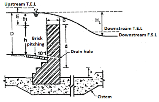
Fig.: Rectangular crest (Q<14 cumecs)
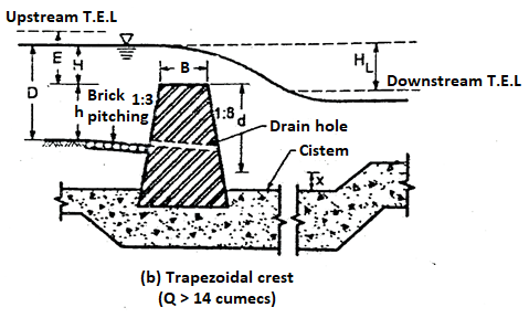
Fig.: Trapezoidal crest(Q>14 cumecs)
For trapezoidal crest
- Top width (B)=0.55

Upstream batter=1:3
Downstream batter = 1:8
- Base width is determined by the batter
Discharge (Q) = 1.99  … (2)
… (2)
c. Crest level
- From Equations (1) and (2), the value of H is known
∴RL of crest =upstream F.S.L -H
H = Height of crest above bed=D-H
- Note that, if the fall exceeds 1.5 m. The stability of the crest wall should check by actual analysis slope for brick pitching is 10: 1 and this pitching is laid for 2 to 4 m length upstream of the crest and at the level of brick pitching, drain holes are provided in crest to drain out the upstream bed at the time of closing the canal.
2. Design of cistern
- Depression and the length of the cistern are given by the following equations:
 … (3)
… (3)
 …. (4)
3. Design of impervious floor
- There are two theories namely Khosla's theory and Bligh's theory (for small works) by which total length of an imperious floor.
- When there is water on the upstream side upto the top of the crest and there is no flow to the downstream side, then the maximum head is going to be occur
- The maximum seepage head is equal to 'd' as shown in Fig. A minimum length (ld) at the downstream of the crest out of the total impervious floor length is given by the expression as follows:
Ld = 2(D+1.2) + HL metres …. (5)
- Excluding the minimum length provided to the d/s side, the balance length of an impervious floor can be provided to u/s side.
- A minimum thickness of 0.3 m to 0.4 m is provided for the floor to the upstream of the crest.
- The actual thickness of the floor on downstream of crest depends upon the uplift pressures.
- Top lining brick on edge in cement mortar should be provided to cistern and downstream impervious floor. Due to this provision of top lining brick on edge floor can be repaired whenever required.
- At the downstream of the impervious layer, a vertical cut-off of 1 to 1.5 m depth is always provided.
4. Downstream protection:
Downstream protection involves:
a. Bed protection
- Downstream of bed is protected by providing dry brick pitching about 200 mm thick resting on ballast o size 100 mm.
- Table shows the details of bed pitching.
Head over crest (metres) | Total length of pitching on the d/s (metres) | Remarks | Curtain wall | |
Number | Depth(m) | |||
Upto 0.3 | 3.0 | Sloping at 1m in 10 | 1 | 0.30 |
0.3 to 0.45 | 3.0+2HL | Horizontal upto end of masonary wings and then sloping at 1 in 10 | 1 | 0.30 |
0.45 to 0.60 | 4.5+2 HL | 1 | 0.45 | |
0.60 to 0.75 | 6.0+2 HL | 1 | 0.60 | |
0.75 to 0.90 | 9.0+2 HL | 1 | 0.75 | |
0.90 to 1.05 | 13.5+2 HL | 2 | 0.94 | |
1.05 to 1.20 | 18.0+2 HL | 2 | 1.05 | |
1.20 to 1.50 | 22.5+2 HL |
| 2 | 1.35 |
b. Side protection
- One brick on edge is provided in side pitching after the warped wings.
- Side pitching is warped from a slope of 1:1 to 1:1.5. In this 1 case, depth is equal to ½ to the downstream water depth. A toe wall of having 1.5 brick thickness supports the pitching work.
c. Downstream wings
- For a length of 5 to 8 times
 , from the crest, the downstream wings are vertical. These wings are than warped to a slope of 1:1 to 1.5:1
 - The wings are kept with a circular arc, tangential at the starting point of warp in plan.
- These walls are designed as earth retaining structures. Actual design calculations are required to be made for heavy work.
5. Design of upstream approach
- The upstream wings can be splayed straight at an angle of 45° for the discharge upto 14 cumecs.
- The wings are kept segmental with radius equal to 5 to 6 times H with an angle of 60° at the centre and then it is made straight into the berm earth banks should be a minimum of 1 m upstream wing foundations rest on the upstream impervious floor.

Fig.: Sarda type of fall
Q30) Explain the design of straight glacis fall?
A30)
The following are the various steps involved in the design of Glacis fall:
Steps Involved in the design of Glacis fall
- Design of crest
- Design of cistern
- Design of impervious floor
- Design of downstream protection
- Bed protection
- Side protection
- Curtain wall
5. Design of energy dissipators
- Friction blocks
- Glacis blocks
- Deflector wall
6. Design of downstream expansion
7. Design of upstream approach
1. Design of crest
- Width of the crest is kept equal to 2/3E.
- Slope of upstream glacis is ½:1 and joined tangentially to the crest with a radius of E/2 for non-meter falls.
- E=Height of upstream T.E.L. Above crest as shown in Fig.
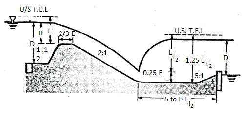
Fig.: Straight Glacis fall
- Slope of downstream Glacis is 2:1 and joined tangentially to the cistern with a radius equal to E where E is height of d/s T.E.L.
- The value of E is determined from the following discharge equation
 … (1)
… (1)
Where Lt= length of the crest;
Q = discharge in cumecs
- Crest level is determined from the following expression.
Upstream T.E.L= Upstream F.S.L+ Velocity head
- Minimum clear length of the crest is expressed in percentage of the bed width of canal.
Table: Recommendation for clear length of crest
Sr.no. | Drop | Clear length of crest (% of the bed width of canal) |
1 | Below 1.25m | 65% |
2 | 1.25 to 3m | 75% |
3 | Above 3m | 85% |
- Note: If glacis fall is combined with bridge, then it can sometimes be flumed.
2. Design of cistern
- Length of cistern = 5 to 6 Er2 refer to Fig.
- R.L of cistern =Downstream T.E.L -1.25 Er2
- Since discharge per meter run, drop HL and the energy of flow (Er2) below the hydraulic jump is known.
3.Design of impervious floor
- The total length of the impervious floor is determined form the value of permissible existing gradient.
- The total length of an impervious floor involves the various length of structures as follows:
a) Length of cistern.
b) Horizontal length of downstream glacis.
c) Crest width.
d) Horizontal length of upstream glacis.
e) Balance length is provided to the upstream.
4. Design of downstream protection
a. Bed protection
- There is no bed pitching provided if a deflector wall is constructed at the upstream end of the floor. The height of deflector wall above d/s bed=
 where D1, is the d/s water depth as shown in Fig.
b. Side protection
1.5 thick dry brick pitching is provided upto a length equal to 3D₁. Toe is 0.4 m wide and D1/2 deep, provided with a minimum depth of 0.5 m. Dry brick pitching rest on toe.
c. Curtain wall
- Curtain wall depth = D1/2 and its width is 0.4 m.
5. Design of energy dissipators:
a. Friction blocks:
- In case of flumed glacis falls, four rows of friction blocks are provided. The height of each block is D1/8 length = 3 × the height of the block.
- The distance between the rows is equal to the height of the blocks.
- The upstream edge of the first block is kept at a distance of five times the height of the blocks from the toe of glacis.
b. Glacis blocks:
- One row of glacis blocks with a same dimension as like friction blocks is provided at the downstream end of glacis if falls is more than 2m.
c. Deflector wall
- With height equal to D1/10 and width equal to 0.4 m, deflector wall is provided at the downstream of cistern.
6. Design of downstream expansion
- The downstream expansion starts from the toe of the glacis in case of a flumed fall. In case of design of downstream expansion. Generally hyperbolic expansion is considered see the Fig. Per hyperbolic expansion.
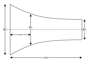
Fig.: Hyperbolic expansion
- The bed width say B, at any distance x from the downstream toe of the glacis is given by the following expression.

Where, Le = Total length of expansion straight 1 in 3 expansion is preferred for small falls.
7. Upstream approach:
- The side walls are splayed at an angle of 45 from the upstream edge of the crest for a non-meter fall and it is further carried straight into berm by a minimum length of 1 m.
- Fig. Shows straight glacis fall.

Fig.: Glacis fall
Q31) Explain Principle and Design of Distributory head regulator and cross regulator?
A31)
Following are the various steps involved in the design of cross-regulator and head regulator.
Steps involved in the design of cross-regulator and head regulator are as follows:
- Design of crest
- Design of downstream floor
- Design of impervious floor
- Design of upstream and downstream protection
- Upstream protection
- Downstream protection
1. Design of crest
- In the design of cross-regulator and head regulator, the discharge (Q) is calculated from the Drowned weir formula.
 … (1)
… (1)
Where, Q = Discharge in cumecs
L = Length of water-way in meters
C₁ = Constant = 0.557
C2=Constant=0.80
d= Depth of downstream water level in the channel measured above the crest
h = Difference in water level upstream and downstream of the channel in meters
Ha = Head due to velocity approach
- Note that if Equation (1) is used, then generally the velocity of approach may be neglected because it is very small. By knowing the value of discharge 'Q' the length of water way can be determined.
For cross regulator-
- The crest level is kept equal to u/s bed level of the parent channel.
For distributary head regulator-
- The crest level is kept 0.3 m to 1 m higher than the crest level of the cross regulator. The crest is joined to the downstream floor by a glacis slope of 2: 1.
2. Design of downstream floor
- There are two flow conditions under which, the level and length of the downstream floor.
Condition 1
- The discharge in the parent channel is not sufficient hence cross regulator gate is partially opened and the off-taking channel is running full or the head regulator gate is kept fully open.
Condition 2
- Full discharge passing through both the head regulator and cross regulator.
- Note that to apply both these conditions, the discharge intensity 'q' and the head loss HL (= h) are known. Therefore, the value of Er2 can be determined from the bleach curves.
D/s floor level= downstream T.E.L -Er2 d/s F.S.L -Er2
- But the downstream floor level calculated from the above relation should not be provided higher than the downstream bed level.
Now, En=Er2+ HL
- Therefore, the depth D1, and D₂ related to En and En respectively are determined form specific energy curve.
- Then, length of the downstream floor = 5 (D₂-D₁)
- But the downstream floor should be at least 2/3rd of the total impervious length of the floor.
3. Design of impervious floor
- From the consideration of permissible exit gradient, the total length of the impervious floor should be determined.
d1=Depth of the upstream cut off= (1/3 upstream water depth +0.6) meter
d₂ =Depth of downstream cut off= (1/2 downstream depth +0.6) meter
Hs= Maximum static head= Upstream F.S.L-Downstream floor level
GE=  for which
- Then,
 (= bd2) is known from the exit gradient curves. Therefore, the total length of the impervious floor is known.
 - The floor thickness is determined form the considerations of uplift pressure.
- From the practical view and considerations, a minimum thickness of 0.3 m to 0.5 m is provided.
4. Design of upstream and downstream protection
- d1 = Upstream scour depth= (1/3 upstream water depth +0.6) meter
- d2 = Downstream scour depth = (1/2 downstream water depth+ 0.6) meter
- The scour depths d1 and d₂ are below the related bed levels and protection works are designed related to these values of depth.
a. Upstream protection
- The upstream protection is done by providing block protection having cubic contents (i.e., d1 m3/m). The cubic contents of upstream launching apron is kept equal to 2.25 d1 m³/m width of regulator.
b. Downstream protection
- For downstream protection, cubic contents d of downstream inverted filter is kept equal to d2 m3/m. The cubic contents of downstream launching apron is kept equal to 2.25 d₂ m³/m width of regulator.
- Fig. Shows the section of cross regulator.
- Fig. Shows the section of distributary head regulator.
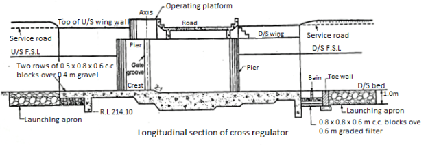
Fig.: Section of Cross regulator
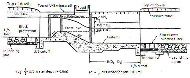
Fig.: Longitudinal section of distributory head regulator
Q32) What is Canal Escape?
A32)
- Definition: Irrigation structures constructed to escape excess water from the canal to some natural drainages are called escapes.
- These are located at 5 to 10 km along major canals.
- Escape consists of headwall parallel to the bank. It has opening to allow canal flow water through pipe and gate. The other end is attached to waste canal which is lined for some distance. This waste canal takes discharge to nearby valley.
- The escapes are provided at a distance depending upon importance of canal.
- It is a structure constructed on an irrigation channel to dispose off the surplus water, from the channel. So, it is also called as surplus water Escape or Canal Surplus Escape. It also has same more important functions to carry out like.
- It can scour out the silt from the bed of the head-reaches. So, it is also called as Canal Scouring Escape.
- It can maintain the F.S.I. At the tail end of the channel. So, it is also called as Tail Escape.
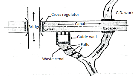
Fig.: Canal Escape
Significance of canal Escapes:
- Following are some of the important causes of having surplus water in an irrigation canal, such as,
- Due to human error, the function of regulation does not work properly.
- Due to unexpected heavy rains in the upper reaches extra water enters in the channel.
- Due to closing of the outlets of the channels, by the farmers (This may happen due to sudden change in the market demand for a particular crop or fruits or vegetables, farmers, stop irrigating that 'crop' or plant) which rises the level of water in the channel to effect into surplus water.
Q33) Explain the classification of Escape?
A33)
- Classifications on the basis of the functions
- Canal Surplus Escapes or Surplus Water Escapes
- Canal Scouring Escapes
- Tail Escapes
2. Classifications on the basis of the structural design
- Regulator or sluice types of Escapes
- Weir type of escapes
- We have already seen that the escapes have various functions. So, on the basis of the functions; can classify the escape as,
- Canal Surplus Escapes or Surplus Water Escapes.
- Canal Scouring Escapes
- Tail Escapes
- On the basis of the functions to be carried, the design of the escapes also varies. On the basis of the structural design of these escapes; they can be classified as follows,
1. Regulator type escape:
- It is like a small regulator, which is provided in the channel bank. It has gates, which are supported on pier. The flow of water through the escapes, is controlled by these gates.
2. Weir Type Escape:
- A weir type escape, is like a weir with the crest of the weir wall at the full supply level (F.S.L) of the channels, at the site of the escape.
- As soon as the water level in the channel rises above the F.S.L the water starts flowering over the crest of the escape and through it is allowed.