Unit - 4
Canal Head works
Q1) What is the function of Canal headwork?
A1)
Following are the various function of diversion head works.
- Diversion head works regulates the flow of water into canal.
- It increases the level of water in the river or streams. Due to increase of the level of water and thus increases the command area for irrigation.
- It does not allow the entry of silt, gravels into canals and thus control the entry of slit, gravels into the canal.
- It helps in regulating the supply of water into canals.
- It helps in controlling the vagaries of the river and streams.
- It creates a small pond act as a short storage pond for a small period on its u/s and thus provide some pondage.
- It minimizes the fluctuations in the level of supply in the river streams.
- It increases the water level on its u/s side.
Q2) Explain the layout of headwork?
A2)
A diversion head work consists of following component:
- Weir (barrage)
- Under sluice
- Fish ladder
- Divide wall
- Canal head regulator
- Silt excluder
- Guide bank
- Marginal bunds
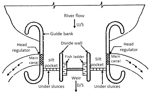
Fig: Layout of diversion headwork
Weir (Barrage)
- A structure constructed across river to raise water so as to divert this raise water into canal and this raising of water is mostly done by the crest wall constructed across river and very small part or nil part is by shutter sometimes if provided on its top is called as weir and when (most water stored) storing of water is done by gates or shutters and small part or nil part of water is by the raised crest then such structure constructed is known as barrage.
- In weir affluxed caused is more during high floods while in barrages afflux is nil or minimum as flow of water is controlled by shutters during floods gates are opened and thus afflux is controlled.
Under Sluice
- Under sluice are the opening provided in the body of weir at low level.
- These are located at same side from which canal is taking off. The crest of under sluice is kept lower than crest of weir due to which water is attracted towards it and thus ensure easy diversion into canal.
Functions of under sluice:
- It controls entry of silt into canal.
- It lowers the HFL
- It helps in passing low river floods without lifting shutters.
- It helps to pass silt on downstream side of weir.
- Whenever silt is to remove the gates of head regulator are closed and of sluices are opened through these sluices the silt which is deposited is removed and it goes on downstream side when all silt removed sluice gates are closed and regulator gates are opened.
Divide Wall
It is wall constructed between under sluices and the car at right angle to the axis of the weir to divide the river channel.
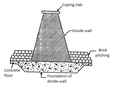
Fig: Divide wall
Functions of divide wall
- It separates the under sluices from weir.
- It also helps in reducing velocity of flow near the head regulator due to which silt is deposited and clear water passes into canal.
- It prevents vortices means flow in circular motion.
Fish Ladder
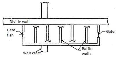
- Definition: It is passage provided adjacent to divide wall for the movement of fish from upstream to downstream and vice versa is called fish ladder.
- It has been observed that fish moves from cold water to warm water and in monsoon they again move towards upstream or downstream of the work.
- These are provided with various fashion like sluice type in which the baffle wall is in zig zag way over flow type in which V notches are provided in staggered arrangement etc.
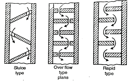
Fig: Fish ladder
Silt Exclusion Devices
- Definition: The devices which are constructed at the head of main canal which prevents entry of silt particles into canal are called as silt exclusion devices.
Silt Ejectors
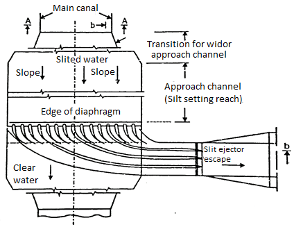
Fig: Silt ejector
- Definition: The structure which is constructed across the canal to eject silt accumulated in canal section is as called silt ejector.
- Silt ejector consists of tunnel which is constructed parallel to the flow of the canal and then turns 90° to eject silt.
- The length of tunnel provided may be different. These are provided with sufficient slope. So that silt should not be deposited in its bed.
Silt Excluder
- It is structure in the under sluices to pass water containing silt on downstream through under sluices so that only clear water enters into the head regulator.
- These are parallel to the axis of head regulator, Silt excluder prevents the entry of silt into the canal.
- It consists of number of small tunnels with their roof slab at same level. The crest of the head regulator and the tunnels are of different lengths.
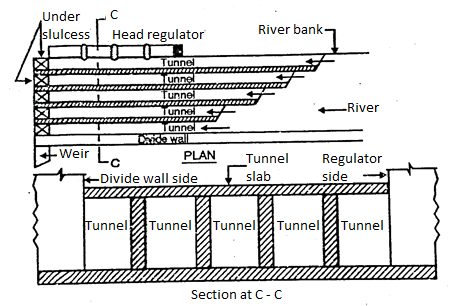
Fig: Silt Excluder
Guide Bank
- Guide banks are provided on either side of diversion head work in alluvial soil to prevent river from out flanking the work.
- The main object of guide banks are:
- It prevents oblique approach to the head regulator.
- It protects regulator from river attack.
- It increases maximum discharge at all point.
- It prevents out flanking of structure,
- It creates reasonable water way for a weir.
Marginal Embankment
- Marginal embankment is provided on either bank of river upstream of diversion head work to protect the land and property which is likely to be submerged during flood.
- Marginal embankment helps in -
- It increases the intensity of flood.
- It increases bed level of the river by silting.
- It protects land and property which is likely to be submerged.
Q3) What are the types of weirs?
A3)
Weirs are classified as follows:
- Gravity weir
- Non gravity weir
- Vertical drop weir
- Rock fill weirs
- Concrete weirs
1. Gravity weir
- Definition: When the weight of weir balances uplift pressure caused by the head of water seeping below weir it is called as gravity weir.
2. Non gravity weir
- In non-gravity weir the uplift pressure is largely resisted by weight of concrete slab with the weight of divide piers.
- Non gravity weirs are further divided into following types:
Vertical drop weir
- This type of weir consists of horizontal floor and a masonry crest with vertical or nearly vertical downstream face and the shutters are provided at the crest.
- Most of storage is done by raised crest and some storages by shutters provided over the crest.
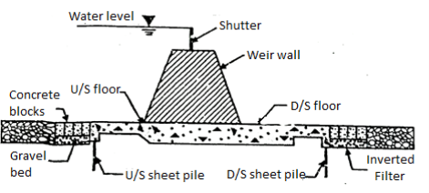
Fig: Vertical drop weir
Rock fill weir
- It is also called as dry-stone slope weir. It is suitable for fine sandy foundation stone are mainly used for construction of such type of weir and hence requires large quantities of stone.
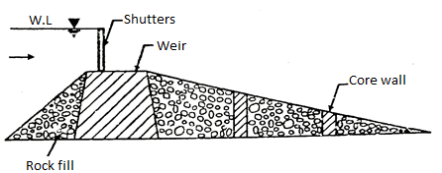
Fig: Rock fill weir
Concrete weir
- These are suitable for permeable foundations. In such weirs sheet piles are provided on both upstream and downstream floors, in order to destroy the energy of water.

Fig: Concrete weir
Q4) What are the components of weir?
A4)
Component Parts of Weir are as follows:
- Body of weir
- Upstream apron
- Upstream curtain wall
- Downstream apron
- Downstream curtain wall
- Crest
- Shutter
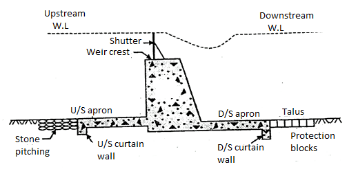
Fig: Component of weir
Body of weir
- It is generally of masonry. Its function is to raise water level on upstream side. It should be strong and enough to resist water pressure.
Upstream apron
- It protects weir during floods from eroding action. Its length depends upon discharge of river and weir length. It also helps to prevent leakage in subsoil and it minimizes uplift water pressure if any exist.
Upstream curtain wall
- It is provided to reduce the uplift pressure. Its length depends upon the nature of soil.
Downstream apron
- Downstream apron serves like energy desipitors. These are provided for destroying kinetic energy and thus prevent downstream side from erosion. Its length depends upon the height of fall nature of soil discharge etc.
Downstream curtain wall
- It protects downstream floor from uplift pressure. Its length is depended upon the length of weir.
Crest
- It is the top of the weir. It must be strong and durable as it has to resist water pressure oftenly during floods. During flood water flows over from the crest.
Shutter
- Shutters are provided at the top of weir. It also helps in raising the water level on upstream of river. Shutters must be strong to resist water pressure.
Barrage
- Definition: If storage of water is done by gates and very small portion or nil portion of water is stored by raised crest then the barrier is called as barrage.
- The gate controls the flow of river water depending upon necessity by raising or lowering the gates. One can construct road way across the river with minimum construction cost. Therefore, barrages are always preferred than that of a weir.
Q5) What are the advantages and disadvantages of Barrage?
A5)
Advantages of Barrage over Weir:
The following are the advantages of barrage over a diversion weir:
- As small afflux is caused above normal HFL the area under flooding is less.
- As compared to weir these are just like low-cost flood bank.
- These are more safe than weir as afflux is less.
- It is economical as cost of protective and energy dissipation work is less.
- The control of flood discharge is achieved with the help of gates.
- These are preferred in flat longitudinal sloped region and flow having heavy chances of silt.
Disadvantages of Barrage:
- Storage capacity is less
- Maintenance cost is more
- Initial cost is more.
Q6) Explain the design of vertical drop and sloping glacis weir?
A6)
The following are the various steps involved in the design of Glacis fall:
Steps Involved in the design of Glacis fall
- Design of crest
- Design of cistern
- Design of impervious floor
- Design of downstream protection
- Bed protection
- Side protection
- Curtain wall
5. Design of energy dissipators
- Friction blocks
- Glacis blocks
- Deflector wall
6. Design of downstream expansion
7. Design of upstream approach
1. Design of crest
- Width of the crest is kept equal to 2/3E.
- Slope of upstream glacis is ½:1 and joined tangentially to the crest with a radius of E/2 for non-meter falls.
- E=Height of upstream T.E.L. Above crest as shown in Fig.
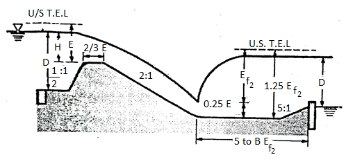
Fig.: Straight Glacis fall
- Slope of downstream Glacis is 2:1 and joined tangentially to the cistern with a radius equal to E where E is height of d/s T.E.L.
- The value of E is determined from the following discharge equation
 … (1)
… (1)
Where Lt= length of the crest;
Q = discharge in cumecs
- Crest level is determined from the following expression.
Upstream T.E.L= Upstream F.S.L+ Velocity head
- Minimum clear length of the crest is expressed in percentage of the bed width of canal.
Table: Recommendation for clear length of crest
Sr.no. | Drop | Clear length of crest (% of the bed width of canal) |
1 | Below 1.25m | 65% |
2 | 1.25 to 3m | 75% |
3 | Above 3m | 85% |
- Note: If glacis fall is combined with bridge, then it can sometimes be flumed.
2. Design of cistern
- Length of cistern = 5 to 6 Er2 refer to Fig.
- R.L of cistern =Downstream T.E.L -1.25 Er2
- Since discharge per meter run, drop HL and the energy of flow (Er2) below the hydraulic jump is known.
3.Design of impervious floor
- The total length of the impervious floor is determined form the value of permissible existing gradient.
- The total length of an impervious floor involves the various length of structures as follows:
a) Length of cistern.
b) Horizontal length of downstream glacis.
c) Crest width.
d) Horizontal length of upstream glacis.
e) Balance length is provided to the upstream.
4. Design of downstream protection
a. Bed protection
- There is no bed pitching provided if a deflector wall is constructed at the upstream end of the floor. The height of deflector wall above d/s bed=
 where D1, is the d/s water depth as shown in Fig.
b. Side protection
1.5 thick dry brick pitching is provided upto a length equal to 3D₁. Toe is 0.4 m wide and D1/2 deep, provided with a minimum depth of 0.5 m. Dry brick pitching rest on toe.
c. Curtain wall
- Curtain wall depth = D1/2 and its width is 0.4 m.
5. Design of energy dissipators:
a. Friction blocks:
- In case of flumed glacis falls, four rows of friction blocks are provided. The height of each block is D1/8 length = 3 × the height of the block.
- The distance between the rows is equal to the height of the blocks.
- The upstream edge of the first block is kept at a distance of five times the height of the blocks from the toe of glacis.
b. Glacis blocks:
- One row of glacis blocks with a same dimension as like friction blocks is provided at the downstream end of glacis if falls is more than 2m.
c. Deflector wall
- With height equal to D1/10 and width equal to 0.4 m, deflector wall is provided at the downstream of cistern.
6. Design of downstream expansion
- The downstream expansion starts from the toe of the glacis in case of a flumed fall. In case of design of downstream expansion. Generally hyperbolic expansion is considered see the Fig. Per hyperbolic expansion.
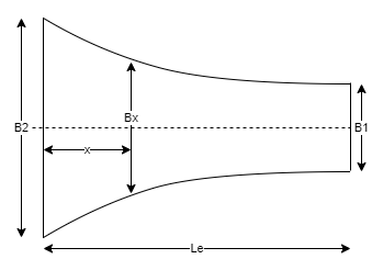
Fig.: Hyperbolic expansion
- The bed width say B, at any distance x from the downstream toe of the glacis is given by the following expression.

Where, Le = Total length of expansion straight 1 in 3 expansion is preferred for small falls.
7. Upstream approach:
- The side walls are splayed at an angle of 45 from the upstream edge of the crest for a non-meter fall and it is further carried straight into berm by a minimum length of 1 m.
- Fig. Shows straight glacis fall.

Fig.: Glacis fall
Q7) What is Cross Drainage work?
A7)
- Structure constructed for crossing canal water safely over or under the drainage water is called as cross drainage work.
- C-D work is a structure which carry the discharge of a natural stream or river or nala across a canal intercepting the stream or river or nallah.
- A cross drainage work is generally expensive and should be avoided as for as possible by diverting one stream to another or changing the alignment of -the canal.
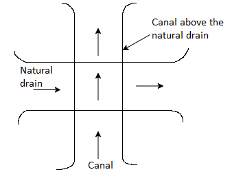
Fig: Natural drain below the canal
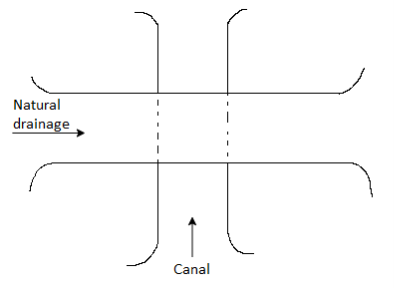
Fig: Natural drainage above the canal
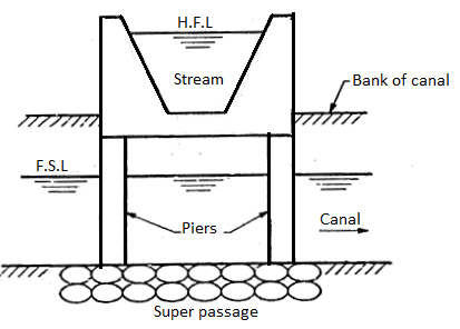
Fig: C.D works
Q8) What is the necessity of cross drainage work?
A8)
- C. D. Work is a structure constructed on a canal where it is crosses a natural drain like a stream, nala or river. In short, C. D. Works is the structure which carries the discharge of a natural drainage such as stream, nala or river across a canal intercepting the natural drainage.
- The cross-drainage work is essential so as to dispose of the drainage water and hence C. D. Work is built in such way that canal supply remains uninterrupted.
- Canal at a cross-drainage work (C. D. Work) is generally taken over the drainage or below the drainage.
- At the crossing point of canal and C. D. Work, the water of canal and the drainage get intermixed, hence for the smooth running of the canal with its design discharge, the cross-drainage works is necessary.
- The water shed canals do not cross natural drains such as stream or river, but in actual practice of the canal network, this ideal condition may not be available and obstacles such as river, streams may be come across the canal, therefore, C. D. Works should be provided for running the irrigation system.
- The site condition of the crossing point may be such that without any suitable structure, it is very difficult to divert the water of canal and drainage. To avoid this the C. D. Works should be provided to maintain natural direction of natural drainages.
Q9) What is aqueduct?
A9)
- It is mitigation structure constructed for passing canal water over the drainage work.
- An aqueduct consists of masonry or concrete trough of rectangular section supported on abutment and piers and stream flows below the trough through abutment and piers.
- Aqueduct should align normal to the canal and under the following situation an aqueduct is constructed.
- When discharge of stream is more as compared to discharge through canal.
- And sufficient clearance is available i.e., bed level of canal is at higher level than high flood level of stream.
Sometimes a trough is divided into two compartment and second compartment is covered with slab which is later useful for roadways.
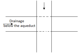
Fig: Aqueduct
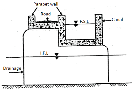
Fig: Aqueduct
Q10) What is Siphon aqueduct?
A10)
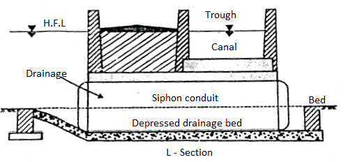
Fig: Syphon aqueduct
- When HFL of the drainage is above or touches CBL (Canal Bed Level) but lower than FSL and drainage is small this type of aqueduct is preferred. In this type canal is at higher level than the drainage.
- It consists of pipe aligned normal to the canal at sufficient depth below CBL. The canal is flumed and taken cross through trough.
- The water flows under hydrostatic pressure through this depression in order to avoid deposition of silt a small slope is provided to give self-cleaning velocity.
Q11) What is Super Passage?
A11)
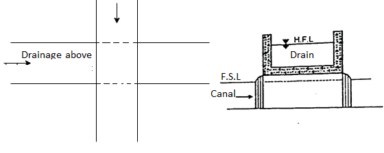
Fig: Super passage
- It is structure constructed at point of crossing where drainage water is taken over the canal. In this case stream passes at higher level than FSL of canal.
- The main object of super passage is to take stream discharge safely across canal and at higher level.
- In this case stream passes over the canal through masonry trough which is supported on supporters. (e.g., abutment, piers etc.). Stream is always flumed by providing suitable wing wall.
Super passage is classified as follows as:
- Pipe super passage
- Syphon super passage
1. Pipe super passage
- In this case pipe is provided for carrying drainage water over the canal. Pipe super passage is provided only if discharge is less. The main disadvantage of these type of super passage is that if silt is deposited it is difficult to clear it off.
2. Syphon super passage
- In this type the bed of canal is depressed so that FSL should not touch the roof of water way.
Q12) What is canal siphon?
A12)
- When two canals cross each other and one of the canals is syphoned under the other, then hydraulic structure at crossing is termed as canal syphon or canal siphon.
- In case of canal syphon, F.S.L. Of the canal is much above the bed level to the drain.
- In canal syphon, the canal bed is lowered.
- Canal runs or operates under syphonic action under the trough.
- Fig. Shows the canal siphon.
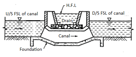
Fig: Canal siphon
Q13) What is level crossing?
A13)
- This type of cross drainage work is adopted when bed level of canal and drainage is same. In this case both water allows to mix with each other. The regulators are provided on downstream side of drainage and canals to regulate discharge. Regulators are provided with lift gates.
- In order to protect bed from eroding action suitable stone pitching is provided on bed and sides of canal on upstream and downstream side.
- During dry season downstream drainage regulator is kept closed and canal regulator is kept open so that canal water flows smoothly and during floods drainage regulator is opened to pass flood water.
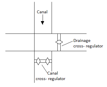
Fig: Level crossing
Q14) Explain the Investigation and planning of Dams and Reservoir?
A14)
- When any type of reservoir is to be constructed, various investigations are made through different field surveys. Which are as follow:
A: Engineering surveys
B: Geological surveys
C: Hydrological survey
A: Engineering surveys
- Under these surveys, the site of the reservoir, and other associated work is surveyed and a contoured plan (showing the relief of the area) is prepared.
- From this plan only, the storage capacity of the reservoir and the water spread area, at various levels (elevations) is calculated as shown below.
- The water spread area of the reservoir at any elevation is determined, directly by measuring the area covered by a contour of the elevation, by the help of the planimeter.
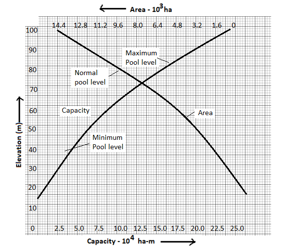
Fig: Elevation area and elevation capacity curve
- This change in the water spread areas at different height can be plotted on a graph capacity on 'x' axis and elevation on 'y' axis. As shown in Fig.
- In the line graph, Maximum pool level, Normal pool level, and minimum pool level is shown.
- By taking the contour areas at equal interval and by summing up various formulae, the storage capacity of any reservoir can be calculated Following the formulae used for such calculations.
- It 'V' is storage volume and A₁, A2, A3….An are the areas covered by the successive contours, with an interval of 'h'. Three different formulae can be sued for this purpose.
(a) Trapezoidal formula

(b) Cone formula

(c) Prismoidal formula

- By using any above-mentioned formulae - the storage volumes at various elevation. Are calculated and are plotted in the above-mentioned elevation capacity curves. Shown is Fig.
- These maps also indicate, the area and the property, which would go under water when, the reservoir is filled upto a certain elevation. This helps to calculate the compensation to be paid to the farmers and other owner of the land and the time. Before they should vacate the area to be submersed under the water of the reservoir
B: Geological Survey:
- These surveys are necessary to confirm the followings:
- Suitability of foundation for the darn.
- Water tightness of the reservoir basin.
- Location and estimation of the store quarry, to be used for the construction work (the cost of transport is added to the total co.t of the reservoir)
- On the basis the type and height of the proposed dam, the exploration of the sub surface is carried out, to calculate, the depth of the over burden to be excavated and removed for the laying the foundation, the natural of rock its formation and the extent of fault zone (if the rock has such fault).
- In case of earthen dams, or low dams such sub-surface exploration, gives information about the soil properties at various depths on the basis of the information collected helps in devising a suitable programme B of foundation treatment (say by grouting) before the actual construction is taken up.
- These geological surveys also help to generate the information about proportion of cavities or pores in the rocks. Which is the basic cause of escape of water through such rocks in the adjacent valley, if the proportion of such pores is less it is treated but if it is wide spread, the site of the reservoir is changed.
- For the construction of dam and other works like embankment work, diversion hand work, canal regulation work etc., a huge quantity of building material is required. The availability of material and the distance of such location from the dam site, also is an important criteria to select a site.
- So, the information collected by through such geological field surveys help to calculate the stability and usability of the reservoir.
C: Hydrological surveys
- The whole of the planning of any reservoir is based on the estimates of the total quantity of water to be available in the stream, from season to another season i.e., the total volume of water during summer and rain season and the yearly average availability of water. Through the hydrological surveys, two types of investigations are made
- Study of runoff pattern of the stream, at the proposed dam site: This helps to determine the storage capacity of the expected reservoir.
- To study the hydrograph of worst flood.
- This helps to determine the methods to take care of the excess water from the reservoir like spill ways gates etc.
- So, in short, engineering surveys help to locate the site, the geological surveys help to determine the strength of the foundation and expected losses through the rock pores and the hydrological surveys help to calculate to total amount of water, available in the stream and the danger level of worst floods, etc.
- On the basis of the information collected by their surveys the selection of the dam site is made; for the actual select of the dam site following factors are considered.
Q15) Explain the zones of storage?
A15)
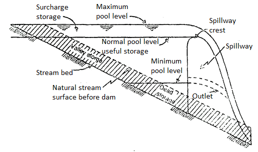
Fig: Zones of storage
The water in the storage of reservoir can be classified on the basis of two different criteria.
- On the basis of the surface or pool level.
- On the basis of functions of the water.
On the basis of surface or pool level
The storage in the reservoir can be classified on the base of the different pool levels as:
- Normal Pool Level (NPL)
- Minimum Pool Level
- Maximum Pool Level.
1. Normal pool level:
- During the ordinary operation conditions in the reservoir, this is the maximum elevation, up to which the water surface will rise.
- In case of non-gated spillway, this normal pool level is determined by the elevation of the spillway crest; but it has a gated spillway, then this normal pool level is determined by the top of the spillway gates. This normal pool level is also called as Full Reservoir Level (F.R.L.) or Full Tank Level (FTL).
2. Minimum pool level:
- This is the lowest elevation to which the water is drawn from the reservoir under the normal condition.
- This minimum pool level, in case of irrigation dam is fixed by the elevation of lowest outlet in the dam, and for the hydel power generating reservoir, by the minimum head required for the effective working of the turbines.
3. Maximum pool level:
- This is the maximum elevation to which the water level will rise, in the reservoir, during the design floods or called as worst flood.
- The maximum pool level is also called as Maximum water level (M.W.L.) of or pool level during design flood.
Zones on the basis of function
The storage in the reserve can be classified on the basis of the functions. They are as follows:
- Useful storage
- Dead storage
- Bank storage
- Surcharge storage
- Valley storage.
1. Useful storage:
- The total volume of water stored between the normal pool level and minimum pool level is known as useful storage (refer Fig.). It is also called as live storage because, the volume of water is made available for various purpose.
- So, in case of multi-purpose projects like Hirakud, Kakrapare or Bhakra-Nangal, the useful storage is sub-divided into conservation storage (for irrigation purpose) and flood control storage (for keeping the excess flood water away from the command areas.)
2. Dead storage:
- The water stored below the minimum pool level of the reservoir is called as dead storage.
- Under the normal operating conditions, this volume of water is not made available for any economic purpose.
3. Bank storage:
- It is a temporarily stored water in the permeable banks of the reservoir. When any reservoir has reached the maximum pool level and has started drain out i.e., its pool level is going down, at that time only, the bank storage goes on increasing.
- The bank storage capacity of any reservoir depends upon the geological conditions i.e., depends upon the type of rock strata which absorbs the water and reaches the state of saturation. This water can be of huge volume. It cannot be used directly but it helps to hold same proportion of water in the reservoir.
4. Surcharge storage:
- The volume of water between the Normal pool level. Maximum pool level of any reservoir is known as surcharge storage.
- The storage is totally uncontrolled because, during floods only it exists and so it cannot be stored for a use in future.
5. Valley storage:
- The amount of water held by the natural stream channel is called as the valley storage. Before the dam is constructed, the natural stream has some amount of water stored in the channel.
- This amount of water varies from stream to stream depending upon the depth of the channel, rate of evaporation, type of bed rock; source of the stream etc.
- When the dam is constructed the storage capacity of the reservoir increases but the net increase in the storage capacity of the reservoir is equal to total storage capacity of the reservoir minus the natural valley storage.
- Except for the flood control the net and the total storage capacity has no importance, for the flood control the effective storage capacity in the reservoir is equal to useful plus surcharge storage minus the natural valley storage which related to the rate of inflow to the said reservoir.
Q16) What are the reservoir losses?
A16)
- The losses of water from the reservoir is the result of three factors namely:
- Evaporation
- Absorption
- Percolation
- These are all natural losses of water, which must be taken into consideration while designing and in the operation stage of any reservoir. Let us check this loss with their proportion to the total losses.
1. The evaporation losses
- The loss of water from the reservoir is proportional to the area of the reservoir. It is expressed in millimetres of depth of water. i.e., It always shows the volume of water lost, per unit area of the exposed surface of water of the reservoir.
- Together with the surface area, other factors, which affect the loss of water through evaporation, are:
- Temperature
- Wind Velocity (over the reservoir)
- Relative Humidity (R.H.) i.e., Higher the temperature faster the rate of evaporation.
- Higher the wind velocity higher the rate of evaporation.
- Higher the relative humidity lesser the rate of evaporation.
- A simple technique is used to measure these losses by using "Pan-Evaporation Method".
2. The absorption losses
- These losses depend upon the type of soil, the bed of the reservoir.
- It has been observed that in the beginning the absorption is high, as the soil is dry and the pores are open but when they are filled and soil gets saturated, the rate of losses through becomes very low and finally almost insignificant.
3. The percolation losses
- These losses depend upon the soil strata.
- If the soil is porous or there are cavities or fissures in the rocks, the rate of percolation is very high and cause, a lot of economic.
Control measures to reduce the losses of water:
- To reduce the losses, the reservoir should be designed to have higher depth and lesser surface area.
- To reduce the wind velocity, wind breakers i.e., the plants must be developed.
- To reduce the rate of evaporation the surface must be covered by a thin, chemical film. (Acetyl alcohol)
- To reduce the percolation losses the grouting techniques should be used.
- To reduce the losses of water it is better to construct the underground reservoirs. (They need high construction cost and maintenance cost).
Q17) Explain the life of a reservoir?
A17)
- The useful life of a reservoir can be calculated by following the steps given below,
- Calculate the capacity efficiency of the reservoir (based on the capacity and the average annual inflow.)
- Calculate the trap efficiency of reservoir by the equation given above.
- Divide the total capacity, for some specific period (in %) e.g., 10% and 90% assume this 10% capacity has been reduced due to the deposition the sediments. Now, calculate the trap efficiency for the remaining 90% of the original capacity of that reservoir and the inflow.
- Get the mean of these two trap efficiencies; which can be assumed as the average value to the trap efficiency for the 10% of the capacity of the reservoir (which is filled totally with the sediments.)
- Calculate the average annual sediments, transported by the stream, or a channel and multiply this figure by the mean trap efficiency.
- Convert this quantity of the sediments, into weights (cubic contents) i.e., volume in hectre meters (ha.m)
- The 10% of the capacity of this reservoir is to be divided by the volume of sediments deposited. This will help to calculate the total number of years required, to till this 10% capacity of the reservoir by the inflow of sediments.
- The above procedure is to be repeated, to calculate the number of years required to fill next 10% capacity of the reservoir i.e., 80%, 70%, 60%,..... Till the capacity of the reservoir becomes 20%.
- The addition of the years, required to till, each of the 10% capacities of the reservoir, will indicate, the useful life of the reservoir.