Unit - 2
Symbols and Sign Conventions
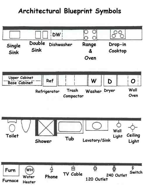
Q1) Draw the architectural blueprint symbols?
A1)
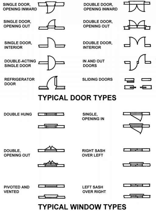
Q2) Draw the typical door and window types?
A2)
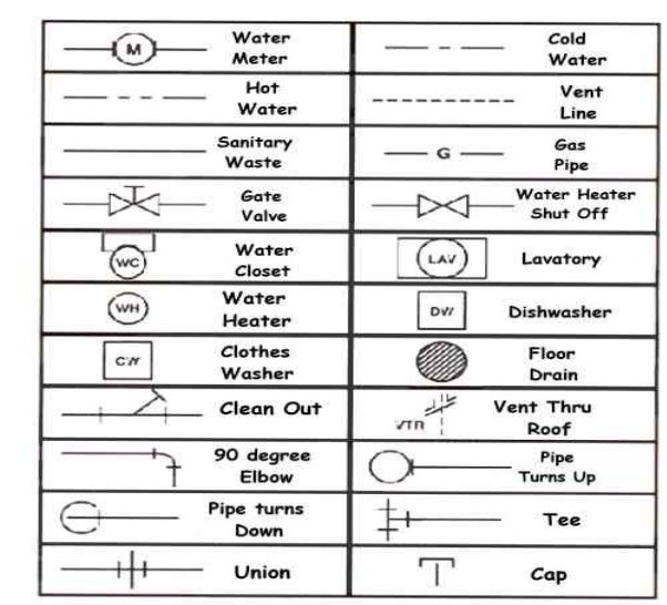
Q3) Draw plumbing symbol?
A3)
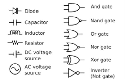
Q4) Draw electrical symbols
A4)
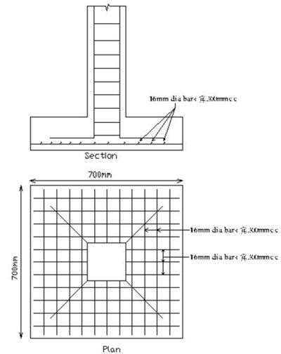
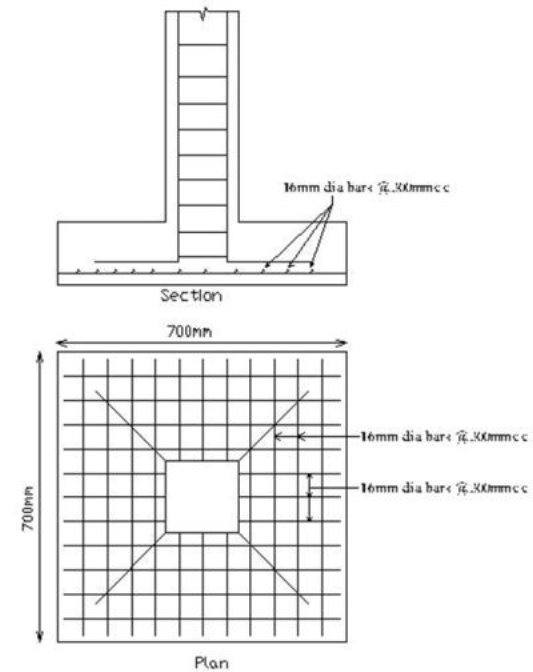
Q5) Draw rebar of column?
A5)
Q6) Show welding symbol?
A6)
Q7) Explain dimensioning standards?
A7) The dimension is the numerical value that is being assigned to the size, shape or location of the feature being described.
• Dimension lines are thin lines that show the extent and direction of the dimension.
Arrowheads are placed at the ends of the dimension line. The dimension line is normally broken to insert the dimension.
• Extension lines are drawn perpendicular to the dimension line and associate the dimension with a particular feature or location.
Extension lines should not touch the object lines - there should be a visible gap between the extension line and the object line.
• A leader line is a thin solid line that is used to associate a note, symbol or dimension with a feature.
Leader lines are typically used to call out radii and diameters.
• A centre line is a light broken line used to indicate the centre line of a feature.
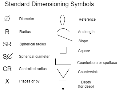
Q8) Draw standard dimensioning symbols?
A8)
Q9) Draw architectural diagram?
A9)
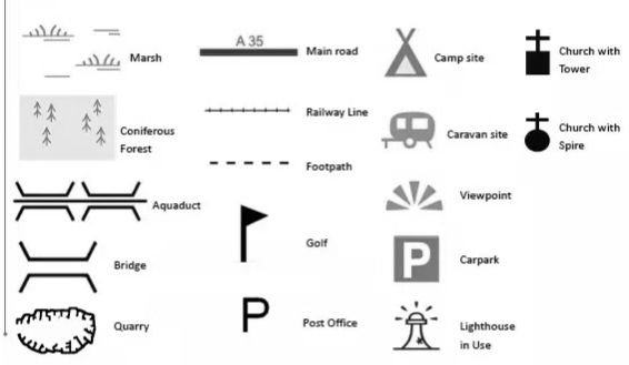
Q10) Draw the material that are used as symbol while drawing the plan?
A10)
