Unit - 1
Introduction to Engineering Mechanics
Q1) Find the magnitude of the two forces, such that if they act at right angles, their resultant is  10 N. But if they Act at 60°, their resultant is
  13 N.
13 N.
A1)
Given Two forces =  and
and 
First of all consider the two forces acting at right angles. We know that when the two given forces is 90 then the resultant force (R).

 …(squaring both sides)
Similarly, when the angle between the two forces is 60 , then the resultant force (R)


 …(squaring both sides)
 (Substituting
  )
)
We know that

 ….(i)
….(i)
Similarly, 
 ….(ii)
Solving equations (i) and (ii),

Q2) A triangle ABC has its side AB = 40 mm along positive x-axis and side BC = 30 mm along positive y-axis. Three forces of 40 N, 50 N and 30 N act along the sides AB, BC and CA respectively. Determine magnitude of the resultant of such a system of forces.
A2)
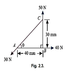
The system of given forces is shown in Fig 2.3.
From the geometry of the figure, we find that the triangle ABC is a right angled triangle, in which the side AC=50 mm. Therefore,

And 
Resolving all the forces horizontally (i.e., along AB)


And now resolving all the forces vertically (i.e., along BC)


We know that magnitude of the resultant force,

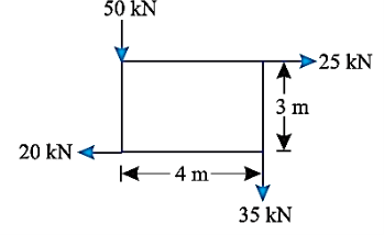
Q3) A system of forces are acting at the corners of a rectangular block as shown in Fig. Determine the magnitude and direction of the resultant force.
A3)
Given System of forces
Magnitude of the resultant force
Resolving forces horizontally,

And now resolving the forces vertically

 Magnitude of the resultant force

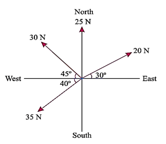
Q4) The following forces act at a point:
(i) 20 N inclined at 30° towards North of East,
(ii) 25 N towards North,
(iii) 30 N towards North West, and
(iv) 35 N inclined at 40° towards South of West.
Find the magnitude and direction of the resultant force.
A4) The system of the forces described can be drawn as:
Magnitude of the resultant force
Resolving all the forces horizontally i.e., along East-West line,


And now resolving all the forces vertically, i.e., along North-South line,


We know the magnitude of the resultant force,

Direction of the resultant force
Let θ= Angle, which the resultant force makes with the East.

Since  is negative and
  is positive, therefore resultant lies between 90
 and 180
 . Thus actual angle of the resultant =180
 -47.7
-47.7 =132.3
Q5) A horizontal line PQRS is 12 m long, where PQ = QR = RS = 4 m. Forces of 1000 N, 1500 N, 1000 N and 500 N act at P, Q, R and S respectively with downward direction. The lines of action of these forces make angles of 90°, 60°, 45° and 30° respectively with PS. Find the magnitude, direction and position of the resultant force.

A5) Magnitude of the resultant force


Resolving all the forces horizontally,


And now resolving all the forces vertically,

We know that magnitude of the resultant force,
Direction of the resultant force
Let θ=Angle, which the resultant force makes with PS
 or
or 
Note:
Since both the values of  and
and  are +ve. Therefore resultant lies between 0
 and 90
 . Positive of the resultant force
Let  Distance between P and the line of action of the resultant force.
Now, taking moments of the vertical components of the forces and the resultant force about P, and equating the same,


Q6) A uniform plank ABC of weight 30 N and 2 m long is supported at one end A and at a point B 1.4 m from A as shown in Fig. Below. Find the maximum weight W, that can be placed at C, so that the plank does not topple.

A6) Weight of the plant ABC =30 N; Length of the plank ABC =2m and distance between end A and a point B on the plank (AB)=1.4m .
We know that weight of the plank (30 N) will act at its midpoint, as it is of uniform section.
This point is at a distance of 1 m from A or 0.4 m from B as shown in figure.
We also know that if the plant is not to topple, then the reaction at A should be zero for the maximum weight at C. Now taking moments about B and equating the same.


Q7) Three forces of 2P, 3P and 4P act along the three sides of an equilateral triangle of side 100 mm taken in order. Find the magnitude and position of the resultant force.
A7)
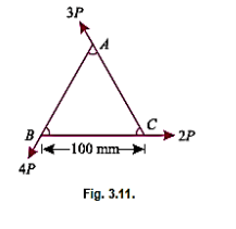
Magnitude of the resultant of force
Resolving all the force horizontally,


And now resolving all the forces vertically.


We know that magnitude of the resultant force

Position of the resultant force
Let  Perpendicular distance between B and the line of section of the resultant force.
Now, taking moments of the resultant force about B and equating the same,


Note: The moment of the force 2P and 4P about the point B will be zero, as they pass through it.
Q8) A square ABCD has forces acting along its sides as shown in Fig. Below. Find the values of P and Q, if the system reduces to a couple. Also find magnitude of the couple, if the side of the square is 1 m.
A8)
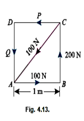
Given Length of square = 1 m
Values of P and Q
We know that if the system reduce to a couple, the resultant force in horizontal and vertical directions must be zero. Resolving the forces horizontally,
100-100 cos 45 - P = 0
 P = 100-100 cos 45
 N
N

Now resolving the forces vertically,


Magnitude of the couple
We know that moment of the couple is equal to the algebraic sum of the moments about any point. Therefore moment of the couple (taking moments about A)


Since the value of moment is negative, therefore the couple is anticlockwise.
Q9) Determine the moment produced by the force F in Fig. Shown about point O. Express the result as a Cartesian vector.
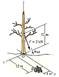
A9) As shown in Fig., either rA or rB can be used to determine the moment about point O. These position vectors are
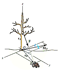
 and
and 
Force F expressed as a Cartesian vector is


Thus


Or


Q10) Two forces act on the rod shown in Fig. Below. Determine the resultant moment they create about the flange at O. Express the result as a Cartesian vector.
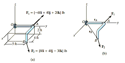
A10)
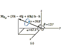
Position vectors are directed from point O to each force as shown in fig 4-15b these vectors are


The resultant moment about O is therefore
 +
+


Q11) Determine the required length of cord AC in Fig. Below so that the 8-kg lamp can be suspended in the position shown. The undeformed length of spring AB is l = 0.4 m and the spring has a stiffness of kAB = 300 N/m.
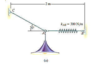
A11)
By simply drawing the free-body diagram, we get,
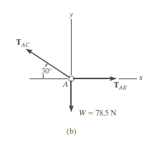
In the force in spring AB is known, the stretch of the spring can be found using  . From the problem geometry. It is then possible to calculate the required length of AC.
Free – Body Diagram
The lamp has a weight W=8(9.81) =78.5 N and so the free body diagram of the ring at a is shown in Fig3-8b.
Equation of Equilibrium
Using the x, y axes


+

Solving, we obtain


The stretch of spring AB is therefore
 ;
;


So the stretched length is


The horizontal distance from C to B fig 3-8a requires


Q12) Determine the force in each cable used to support the 40-lb crate shown in Fig.
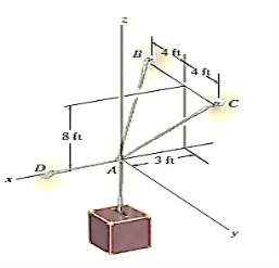
A12)
Initially, free-body diagram is drawn below.
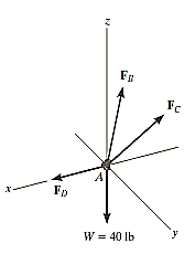
Initially, free-body diagram is drawn below.
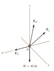
Equations of equilibrium:
First we will express each force in Cartesian vector form. Since the coordinates of points B and C are  and
and  We have


Equilibrium requires


Equating the respective i, j, k components to zero,

 (1)
(1)

 (2)
(2)

 (3)
(3)
Equation (2) states that  . Thus, solving Eq.(3) for
  and substituting the result into Eq.(1) to obtain
  . We have

Q13) Determine the tension in each cord used to support the 100-kg crate shown in Fig.
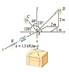
A13)
Free-Body diagram.
The force in each of the cords can be determined by investigating the equilibrium of point A. The free-body diagram is shown in Fig. 3-13b. The weight of the crate is 
Equation of Equilibrium.
Each of force on the free-body diagram is first expressed in Cartesian vector form. Using Eq 2-9 for  and noting point
  for
for  . We have

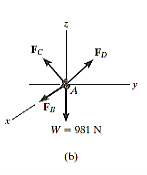


Equilibrium requires


Equating the respective i, j, k components to zero,

 (1)
(1)

 (2)
(2)

 (3)
(3)
Solving Eq.(2) for  in terms of
  and substituting this into Eq. (3) yields
  .
.  is then determined from Eq.(2). Finally, substituting the results into Eq.(1) gives
  . Hence,


Q14) A fixed crane has a mass of 1000 kg and is used to lift a 2400-kg crate. It is held in place by a pin at A and a rocker at B. The centre of gravity of the crane is located at G. Determine the components of the reactions at A and B.
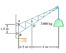
A14)
Strategy:
Draw a free-body diagram to show all of the forces acting on the crane, then use the equilibrium equations to calculate the values of the unknown forces.
Modelling:
Free-body Diagram: By multiplying the masses of the crane and of the crate by  , you obtain the corresponding weights-that is , 9810 N or 9.81N, and 23500 N or 23.5 kN (fig 1). The reaction at pin A is a force of unknown direction; you can represent it by components
  and
and  . The reaction at the rocker B is perpendicular to the rocker surface; thus it is horizontal. Assume that
  and B act in the directions shown.
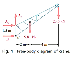
Analysis:
Determination of B. The sum of the moments of all external forces about point A is zero. The equation for this sum contains neither  nor
nor  . Since the moments of
  and
and  about A are zero. Multiplying the magnitude of each force by its perpendicular distance from A, you have
+


Since the result is positive, the reaction is directed as assumed.
Determination of  :
:
Determine the magnitude of  by setting the sum of the horizontal components of all external forces to zero.


Since the result is negative, the sense of  is opposite to that assumed originally.
Determination of  .
.
The sum of the vertical components must also equal zero. Therefore,


Adding the components  and
and  vectorially, you can find that the reaction at A is
  .
.
Q15) Three loads are applied to a beam as shown. The beam is supported by a roller at A and by a pin at B. Neglecting the weight of the beam, determine the reactions at A and B when P = 15 kips.
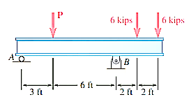
A15)
Strategy:
Draw a free-body diagram of the beam, then write the equilibrium equations, first summing forces in the x direction and then summing moments at A and at B.
Modelling:
Free-Body diagram:
The reaction at A is vertical and is denoted by A (fig.1 ). Represent the reaction at B by components  and
and  . Assume that each component acts in the direction shown.
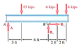
Analysis:
Equilibrium Equations:
Write the three equilibrium equations and solve for the reactions indicated;


Q16) A loading car is at rest on a track forming an angle of 25° with the vertical. The gross weight of the car and its load is 5500 lb, and it acts at a point 30 in. From the track, halfway between the two axles. The car is held by a cable attached 24 in. From the track. Determine the tension in the cable and the reaction at each pair of wheels.
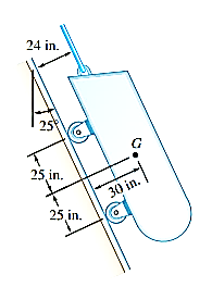
A16)
Strategy: Draw a free-body diagram of the car to determine the unknown force, and write equilibrium equations to find their values, summing moments at A and B and then summing forces.
Modelling:
Free-body diagram: The reaction at each wheel is perpendicular to the track, and the tension force T is parallel to the track. Therefore, for convenience, choose the x axis parallel to the track and the y axis perpendicular to the track (Fig. 1). Then resolve the 5500-lb weight into x and y components.


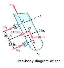
Analysis
Equilibrium Equations:
Take moments about A to eliminate T and  from the computation.
 ;
; 


Then take moments about B to eliminate T and  , from the computation.
 ;
; 


Determine the value of T by summing forces in the x direction.


Q17) The frame shown supports part of the roof of a small building. Knowing that the tension in the cable is 150 kN, determine the reaction at the fixed end E.
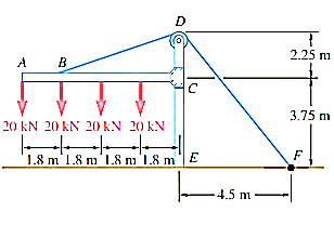
A17)
Strategy:
Draw a free-body diagram of the frame and of the cable BDF. The support at E is fixed, so the reactions here include a moment; to determine its value, sum moments about point E.
Modelling:
Free-body diagram:
Represent the reaction at the fixed end E by the force components  and
and  and the couple
  (fig 1.). The other forces acting on the free body are the four 20 kN loads and the 150 kN force exerted at end F of the cable.
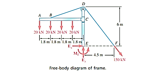
Analysis:
Equilibrium Equations:
First note that

Then you can write the three equilibrium equations and solve for the reactions at E.


+


Q18) A 400-lb weight is attached at A to the lever shown. The constant of the spring BC is k = 250 lb/in., and the spring is unstretched when θ = 0. Determine the position of equilibrium.
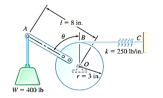
A18)
Strategy:
Draw a free-body diagram of the lever and cylinder to show all forces acting on the body (Fig. 1), then sum moments about O. Your final answer should be the angle θ.
Modelling:
Free-Body Diagram: Denote by s the deflection of the spring from its unstretched position and note that  . Then
Analysis:
Equilibrium Equation: Sum the moments of W and F about O to eliminate the reactions supporting the cylinder. The result is
+


Solving by trial and error, the angle is 