Unit – 1
Introduction to Surveying
Q1) What is surveying?
A1) Surveying is the process of analysing and recording the characteristics of a land area span to help design a plan or map for construction.
Q2) Difference between linear and angular survey?
A2) Linear surveying involves measurement of distances between points on the surface of the earth angular measurements are made between survey lines to determine the angle between the lines
Q3) What are the error in levelling?
A3) There are following types of Errors in Levelling:
1. Instrumental error and Correction
- Correction: Check before use and equalise sights.
- Correction: Check
- Correction: Permanent adjustment.
- Correction: Permanent adjustment
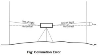
2. Error of Collimation
Collimation error occurs when the collimation axis is not truly horizontal when the instrument is level. The effect is illustrated in the sketch below, where the collimation axis is tilted with respect to the horizontal by an angle a.
3. Curvature & Refraction
Curvature of the earth:
The earth appears to “fall away” with distance. The curved shape of the earth means that the level surface through the telescope will depart from the horizontal plane through the telescope as the line-of-sight proceeds to the horizon.
This effect makes actual level rod readings too large by:

where D is the sight distance in thousands of feet.
Effects of Curvature are:
Atmospheric Refraction:
Refraction is largely a function of atmospheric pressure and temperature gradients, which may cause:
the bending to be up or down by extremely variable amounts.
The atmosphere refracts the horizontal line of sight downward, making the level rod reading smaller. The typical effect of refraction is equal to about 14% of the effect of earth curvature.
Combined Effect of Curvature and Refraction in Survey
The combined effect of curvature and refraction is approximately

The formula for computing the combined effect of curvature and refraction is:
C + R = 0.021K2
Where C = correction for curvature
R = correction for refraction
K = sighting distance in thousands of feet
4.Other sources of errors in levelling and their correction:
Type of Error | Correction |
1. Incorrect setting-up of instrument. |
|
2. Movement of staff from position when changing level station. |
|
3. Staff not held vertically. |
|
4. Parallax: Instrument knocked or moved during backsight-foresight reading |
|
5. Ground heating causes chaotic refraction of light |
|
6. Tripod or rod settles between measurements e.g., Bubble off center |
|
Q4) Write short note on contour?
A4) Contour is a line joining the points of equal elevation.
Contours show distinct characteristic features of the terrain as follows:
i) All points on a contour line are of the same elevation.
ii) No two contour lines can meet or cross each other except in the rare case of an overhanging vertical cliff or wall
iii) Closely spaced contour lines indicate steep slope
iv) Widely spaced contour lines indicate gentle slope
v) Equally spaced contour lines indicate uniform slope
vi) Closed contour lines with higher elevation towards the centre indicate hills
vii) Closed contour lines with reducing levels towards the centre indicate pond or other depression.
viii) Contour lines of ridge show higher elevation within the loop of the contours. Contour lines cross ridge at right angles
Q5) Explain use and method of contour?
A5) Contour maps are extremely useful for various engineering works:
There are two methods of contour surveying:
Direct Method of Contouring
It consists in finding vertical and horizontal controls of the points which lie on the selected contour line. Vertical control levelling instrument is commonly used. A level is set on a commanding position in the area after taking fly levels from the nearby bench mark. The plane of collimation of instrument is found and the required staff reading for a contour line is calculated.
The instrument man asks staff man to move up and down in the area till the required staff reading is found. A surveyor establishes the horizontal control of that point using his instruments.
After that instrument man directs the staff man to another point where the same staff reading can be found. It is followed by establishing horizontal control.
Then several points are established on a contour line on one or two contour lines and suitably noted. After required points are established from the instrument setting, the instrument is shifted to another point to cover more area. The level and survey instrument need not be shifted at the same time. It is better if both are nearby to communicate easily.
For getting speed in levelling sometimes hand level and Abney levels are also used. This method is slow, tedious but got more precision. It is suitable for small areas.
Indirect Method of Contouring
In this the levels are taken at some selected points and their levels are reduced therefore method horizontal control is established first and then the levels of those points found.
After locating the points on the plan, reduced levels are marked and contour lines are interpolated between the selected points.
For selecting points any of the following methods can be used:
Method of Squares
In this method area is divided into a number of squares and all grid points are marked
Commonly used size of square varies from 5 m × 5 m to 20 m × 20 m. Levels of all grid points are established by levelling. Then grid square is plotted on the drawing sheet. Reduced levels of grid points are marked and contour lines are drawn by interpolation
Method of Cross-Section
In this method cross-sectional points are taken at regularly. By levelling the reduced level of all those points are made. The points are marked on the drawing sheets, their reduced levels are marked and contour lines are changed.
The spacing of cross-section relies upon the nature of the ground, scale of the map and the contour interval needed. It varies from 20 m to 100 m. Closer intervals are required if ground level varies.
The cross- sectional line need not be always be at right angles to the main line.
Radial Line Method
In this method several radial lines are taken from a point in the area. The direction of each line is written down. On these lines at selected distances points are marked and levels determined. This method is ideally suited for hilly areas.
For interpolating contour points between the two points any one of the following methods may be used:
(a) Estimation
(b) Arithmetic calculation
(c) Mechanical or graphical method
Q6) What is plane table survey and its principle?
A6) This is the fast method of surveying. In this type of surveying plotting of the plan and field observations can be done parallel. In case of plane table surveying Geometrical conditions of site are manuscript in the map sheet using plane table and alidade after those topographic details are arranged on the map.
The principle of plane table survey is parallelism.
Q7) Explain reciprocal and profile levelling in detail?
A7) Profile levelling is the most common applications of running levels and vertical distance measurement for the surveyor. The results are plotted in the form of a profile, which is a drawing that shows a vertical cross section. Profiles are required for the design and construction of roads, curbs, sidewalks, pipelines, etc Profile levelling refers to the process of determining the elevation of points on the ground at mostly uniform intervals along a continuous line.
Equipment used for profile levelling
Procedure for profile levelling
1. Longitudinal levelling
Profile levelling is the same as benchmark levelling, with one difference. At each instrument position, where an HI is determined by a back sight rod reading on a benchmark or turning point, several additional foresight readings may be taken on as many points as desired. These additional readings are called rod shots, and the elevation of all those points is determined by subtracting the rod shot from the HI at that instrument
location.
The profile drawing is basically a graph of elevations, plotted on the vertical axis, as a function of stations, plotted on horizontal axis. A gridded sheet called profile paper is used to plot the profile data from the field book. All profile drawings must have a proper title block, and both axes must be fully labelled with stations and elevations.
The elevation or elevation scale is typically exaggerated; that is, it is ‘stretched’ in comparison to the horizontal scale. For example, the vertical scale might be 10 times larger. The horizontal line at the bottom of the profile does not necessarily have to start at zero elevation
3 Cross sectioning levelling
Cross sectioning levelling is another method in profile levelling. The term cross-section generally refers to a relatively short profile view of the ground, which is drawn perpendicular to the route centerline of a highway or other types of linear projects.
Cross-sectional drawings are particularly important for estimating the earthwork volumes needed to construct a roadway, they show the existing ground elevations, the proposed cut or fill side slopes, and the grade elevation for the road base. =
There is really no difference in procedure between profile and cross-section levelling except for the form of the field notes. Cross-section rod shots are usually taken during the route profile survey from the same instrument positions used to take rod shots along the centerline.
Cross-section data are obtained at the same locations along the route that are used for the profile rod-shot stations.
Reciprocal levelling:
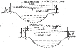
If the level is placed exactly midway between two points and staff reading are taken to determine the difference of level then an error is automatically eliminated but here in the case of a river or valley, it is not possible to set up the level midway between two points on the opposite bank so, the method of reciprocal levelling is adopted.
In reciprocal levelling, the level is set up on both bank of the river or valley and two sets of staff reading is taken by holding the staff on both banks in this case it is found that error is completely eliminated and true difference of level is equal to the mean of the two apparent differences of level.
Procedure:
1. Suppose A and B are two points on an opposite bank of a river. The level is set up very near A and after proper temporary adjustment staff reading are taken at A and B. suppose reading a1 and b1
2.level is shifted and set up very near B and after proper adjustment, staff reading is taken as A and B. Suppose the reading are a2 and b2
Let,
h= true difference of level between A and B
e= combine error due to curvature, refraction and collimation
(Error is +ve and –ve, here error is assumed +ve)
First case:
Correct staff reading A=a1
Correct staff reading B=b1 – e
True difference of level between A and B
h= a1 – (b1-e) ……………………………………………………..eq.1
Second case:
Correct staff reading B=b2
Correct staff reading a=a2 – e
True difference of level between A and B
h= (a2 - e) – b2 ……………………………………………………..eq.2
from (1) and (2)
2h= a1 – (b1-e) + (a2 - e) – b2
2h= a1 – b1 + e + a2 – e – b2
2h= (a1 – b1) + (a2 – b2)
h= [(a1 – b1) + (a2 – b2)] / 2
Q8) What are the formula of areas and volume in survey?
A8)
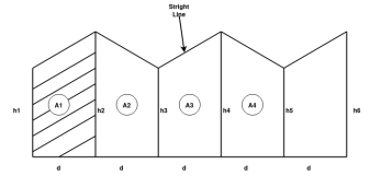
Area 

Total area =A = d (
2. Simpson's rule:


Total area=A=
We need odd number of offsets.
If even number of offsets.
One area is calculated by trapezoidal formula and added with remaining area, calculated by Simpson’s formula.


.
.
.
Total A =?
Volume:
If parallel areas at equal interval are available (or can be found)
1.Trapezoidal formula

2.Simpson's Formula

Q9) What is reduced level in levelling?
A9) Reduced level: elevation of any point with respect to mean sea level.
Q10) What is theodolite survey?
A10) - It is precise instrument for measuring angles in the horizontal and vertical planes.
- It is accurate method or instrument used for measuring horizontal and vertical angles.
- It can use in prolonging survey lines, and finding elevations etc.
Q11) Explain the parts of theodolite in surveying?
A11) Following are part of theodolite
(1) Telescope
- Telescope in theodolite is used for focusing at which object piece and eye piece at other.
- It rotates about horizontal axis in vertical plane.
(2) Vertical circle
- It is fitted to telescope and more simultaneously.
- Graduation is there in each quadrant from 0 to 90 degree.
(3) Index frame
- It is also known as vernier frame or t frame.
- It consists of two parts vertical and horizontal.
- Horizontal arm is used to measure Vertical angle.
- Vertical arm Culps to lock telescope at certain level.
(4) Standards
- They are the frames which support telescope and it is rotated about vertical axis.
- It is also called as A frame.
(5) Upper plate
- It gives support to standards.
- It consists of two vernier with magnifiers which are arranged diagonally.
- Upper clamping screw with respect to tension screw which helps to fixing with the lower plate.
(6) Lower plate
- It contains scale on which 0 to 360 reading are graduate.
- It is also called as scale plate.
- It is attached to outer spindle.
- It consists lower clamping screw.
- If lower clamp is loosened and upper is tightened both plates can rotate together.
- if the procedure is reversed that is lower clamp is tightened and upper loosened and then upper plate is movable and lower plate is fixed.
7) Levelling head
- It contains two parallel triangular plates known as tri batch plates.
- Upper path that is upper tri batch used to level up per plates and telescope with help of levelling screw.
- Lower part i.e., lower tri batch plate and is attached through tripod.
8) Shifting head
- It contains two parallel plates which are right angle to each other with one of them is parallel to trunnion axis.
9) Tripod: -
- It is just stand for theodolite which mounted over it.
- Levelled position is required for tripod to give correct observations.
- Steel shoes are there at the end of tripod leg.
- These legs hold the ground strongly
10) Plumb Bob
- It is cone-shaped weight attached or tie with long thread.
- These is used for entering of theodolite.
11) Magnetic compass:
- It is in circular compass box in centre of upper plate and used for selecting meridian.
Q12) What is trigonometric levelling?
A12) Case (1) if horizontal distance up to the point can be mean.
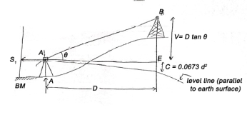
Given values:
1) Distance 'D'
2) Angle=
3) Staff reading 
Vertical height
V = D tan
R.L. of B = RL of B.M. + 
C= combined correction due to Earth curvature/ refraction
= (+) 0.0673  [positive for RL]
Case (2) If distance D cannot be measured
Given (known) values:
1) Distance 'B' = AB
2) Staff readings 
Difference of staff readings 
3) Angle measured
From 
From 
4) RL of BM
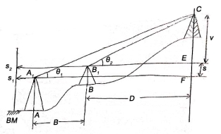

V+S=(B+D) tanθ1 (1)


RL of 
Q13) Derive the expression of Intervisibility of height and distances?
A13)
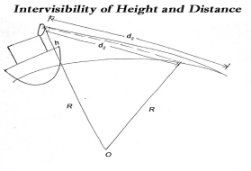
The maximum distance on ground that is visible to a person at certain height is called distance of visible horizon.
If there is no effect of refraction:


 h=in meter, d=in km
Q14) What is baseline?
A14) Baseline is a line between two points on the earth's surface and the direction and distance between them. A baseline is a line that is a base for measurement or for construction
Q15) How to measure the horizontal and vertical angle in theodolite?
A15) a) Horizontal angle:
- Horizontal angle are used to find bearing and direction in control survey.
- It is also used for locating detail when mapping.
b) Vertical angle:
-It is used to find out the height of points and to calculate slope connections.
Measurement of horizontal angle
1) To measure angle of ABC, instrument is set to B.
2) Upper clamp is loosened and lower clamp is fixed.
3) Telescope is turned and vernier A is a set O and Vernier B to 180°.
4) Now lower clamp is loosened and tightened scope is pointed to A and bisect ranging rod at A.
5) Now lower clamp is tightened and lower tangent screw is turned to perfectly bisect ranging rod at A.
6) Now upper clamp is loosened and telescope is turned clockwise to bisect the C which is tightened at upper clamp.
7) Now, vernier reading A and B is noted.
8) Vernier A result in angle directly and vernier B result reading by subtracting initial reading from final reading.
Measurement of vertical angle
1) The zeros of Vernier are set to 0 degree to vertical circle.
2) Telescope is den clamped.
3) Plate bubble are brought to center with foot screw and altitude bubble is brought to centre by clip screw.
4) Telescope in bisect to point A and measure the angle of elevation.
5) Finally reading of vernier is noted and elevation angle is also noted.
6) Now, face of instrument is changed and point A is bisected again and reading are noted.
7) Telescope is lowered slowly and B is bisected to measure angle of depression.
Q16) What are the base line correction in survey?
A16) Chain / Tape corrections
1)Correction due to standardization
Correction per chain length


Total correction

True length of line
Alternate solution of Q → (1)
Core (1) L = 30m and L' = 30.40 m
1) C' = L'-L = 30.40-30 = (+) 0.40m
2) Number of chains = n = 
3) Total correction
 = 42.3×0.40= (+)169.20
4) Total length
l = 12690+169.20 = 16459.2 m
1) Correction due to slope
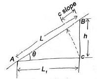
This correction is always a negative correction.
Correct distance between any two points on ground is horizontal distance.
Correction required = L – 

 approximate formula
If  angle is given

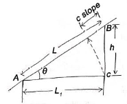

2) Correction due to wrong alignment

Same as slope correction
If endpoint of chain is not put on the straight line between points to be measured


Correction is always negative.
4)Temperature correction
If  is the temperature at the time of standardization.
 is the temperature at the time of measurement
L = length of chain / tape
 = Coefficient of thermal expansion

| Length of chain | Noted down value | Error | Correct |
| Increase | Less | Negative | Positive |
| Decrease | More | Positive | Negative |
5) Pull correction
 = value of pull applied at the time of standardization
 value of pull applied at measurement
L = length of chain / tape
 Cross section area of tape
E = Young's modulus
Pull correction = 
| Error | Correction |
| Negative | Positive |
| Positive | Negative |
6) Sag correction
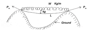

This collection is always negative.
Formal tension
The value of pull 
For which positive pull correction is exactly equal to negative sag correction is called normal tension.

Q17) How to choose baseline?
A17) Choices of Site selection for baseline
Following factors must be accounted for while selecting the site for baseline
a. Ground should be firm and smooth
b. Two ends of baseline must be intervisible.
c. Site must be free from any obstruction throughout base length.
d. Site should be well shaped triangle can be obtained while connecting it’s and stations to main triangulation station.
e. Site should be such that less length of baseline as specified is available.
f. Site must be level.
Q18) What is signal in triangulation?
A18)
- It is small device which is used to define location of triangulation station such that it is easily observed from other stations.
- Signal must be vertical over station.
- It is placed centrally over station mark.
Q19) What do you mean by satellite station?
A19) It is also known as eccentric station.
Satellite station is a false station because it is not possible to set the instrument over the structure false station point is assumed.


