Unit - 3
Compression Member
Q1) Explain compression member?
A1) Compression contributors are structural factors which can be driven collectively or bring a load, extra technically they're subjected best to axial compressive forces. That is, the masses are implemented at the longitudinal axis via the centroid of the member pass segment, and the load over the pass sectional place offers the pressure at the compressed member.
In homes, posts and columns are nearly continually compression contributors as are the top chord of trusses.
A structural member loaded axially in compression is normally referred to as a compression member.
Vertical compression contributors in homes are referred to as columns, posts or stanchions.
A compression member in roof trusses is referred to as struts and in a crane is referred to as a boom.
Columns which are short are subjected to crushing and behave like members under pure compression. Columns which are long tend to buckle out of the plane of the load axis.

The most important styles of column bases are the following:
(i) Slab base
(ii) Gusseted base
(i) Slab Base:
In this association the column stands at once over a metal base plate which rests over a concrete basis.
The base plate is attached to the column flanges with connecting angles with the aid of using welding or bolting.
The column-base plate unit is geared up within side the concrete basis with basis bolts.
(ii) Gusseted Base:
Gusseted base plates are used for columns sporting heavy loads. In this example fastenings are used to connect the bottom plate and the column within side the shape of gusset plates, angles etc.
Compression contributors of roof trusses are composed of unmarried angles or double angles. These contributors can be non-stop contributors (just like the fundamental rafter of the roof truss) or discontinuous contributors (just like the vertical and diagonal contributors of the truss).
The powerful duration KL of the compression contributors can be taken as zero.7 to 1. Zero instances the space among centers of connections relying at the diploma of cease restraint provided.
In the case of contributors of trusses for buckling within side the aircraft perpendicular to the aircraft of the truss, the powerful duration, KL will be taken as the space among the centers of intersection.
Angle Struts of Compression Members:
Single Angle Struts:
The compressive pressure in unmarried or single perspective can be transferred both concentrically to its centroid via cease gusset or eccentrically with the aid of using connecting one in all its legs to a gusset or adjacent member.
Concentric Loading:
When an unmarried perspective is concentrically loaded in compression, the layout power can be decided as within side the case of axially loaded columns.
Common section of compression members
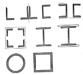
The not unusual place sections used for compression contributors are proven in Fig. With their approximate radii of gyration.
A column or a compression member can be made of many different sections to guide a given load.
Few sections fulfill realistic requirement in a given case. A tubular phase is maximum green and comparatively cheap for the column unfastened to buckle in any route.
The radius of gyration r for the tubular phase in all of the instruction stays identical. The tubular phase has excessive local buckling power. The tubular sections are appropriate for medium loads.
However, it's miles hard to have their cease connections. A stable spherical bar having a cross-sectional place identical to that of a tubular phase has radius of gyration, r a great deal smaller than that of tube. The stable spherical bar is much less comparatively cheap than the tubular phase.
The stable spherical bar is higher than the skinny rectangular phase or a flat strip. The radius of gyration of flat strip approximately its narrow route could be very small.
Theoretically, the rods and bars do face up to some compression. When the duration of structural member is set three m, then the compressive strengths of the rods and bars are very small.
Single perspective sections are not often used besides in mild roof trusses, due to eccentricity on the cease connections. Tee-sections are frequently utilized in roof trusses. The unmarried rolled metal I-phase and unmarried rolled metal channel phase are seldom used as column.
The fee of radius of gyration r, approximately the axis parallel to the web is small. The intermediate extra help switch inside the susceptible route make the use of those sections comparatively cheap.
Sometimes the usage of I-sections and channel sections are favored due to the technique of rolling on the mills, since, the out-to-out dimensions stay identical for a given depth.
This failure is not there with different rolled metal sections. The charges of unmarried rolled metal sections according to unit weight are much less than the ones of constructed-up sections. Therefore, the unmarried rolled metal sections are favored as long as their use is feasible.
Strength of compression member
The power of a compression member is described as its secure load sporting potential. The power of a centrally loaded immediately metal column relies upon at the powerful cross-sectional place, radius of gyration (viz., form of the cross-phase), the powerful duration, the importance and distribution of residual stresses, annealing, out of straightness and bloodless straightening.
The powerful cross-sectional place and the slenderness ratio of the compression contributors are the primary features, which have an effect on its power.
In case, the allowable stress is thought to differ parabolic ally with the slenderness ratio, it could be proved that the performance of a form of a compression member is associated with A/r2.
The performance of a form is described because the ratio of the allowable load for a given slenderness ratio to that for slenderness ratio identical to zero. The secure load sporting potential of compression member of recognized sectional place can be decided as follows:
Step1]
From the actual duration of the compression member and the guide situations of the member, that are recognized, the powerful duration of the member is computed.
Step 2]
From the radius of gyration approximately diverse axes of the phase given in phase tables, the minimum radius of gyration (rmin) is taken. rmin for a constructed-upphase is calculated.
Step 3]
The most slenderness ratio (l/ rmin) is decided for the compression member.
Step 4]
The allowable running stress (σac) within side the route of compression is found similar to the most slenderness ratio of the column from IS:800-1984.
Step 5]
The powerful sectional place (A) of the member is stated from structural metal phase tables. For the constructed-up contributors it could be calculated.
Step 6]
The secure load sporting potential of the member is decided as P= (σac. A), where P=secure load
Q2) A single angle discontinuous strut ISA 150 mm x 150 mm x 12 mm (ISA 150 150, @0.272 kN/m) with single riveted connection is 3.5 m long. Calculate safe load carrying capacity of the section.
A2) Step 1: Properties of angle section
ISA 150 mm x 150 mm x 12 mm (ISA 150 150, @0.272 kN/m) is used as discontinuous strut. From the steel tables, the geometrical properties of the section are as follows:
Sectional area A = 3459 mm2
Radius of gyration rxx= ryy=149.3 mm
Radius of gyration ruu= 58.3 mm, rvv=29.3 mm
Step 2: Slenderness ratio,
Minimum radius of gyration rmin= 29.3 mm
Effective length of strut l= 3.5 m
Slenderness ratio of the strut
Step 3: Safe load
From IS:800-1984 for l/r=119.5 and the steel having yield stress, fy=260 N/mm2, allowable working stress in compression σac =64.45 N/mm2 (MPa)
For single angle discontinuous strut with single riveted connection, allowable working stress
0.80 σac = (0.80 x 64.45) = 51.56 N/mm2.
The safe load carrying capacity

Q3) In case in Example 1, a discontinuous strut 150 x 150 x 15 angle section is used, calculate the safe load carrying capacity of the section.
A3) Step 1: Properties of angle section
Angle section 150 mm x 150 mm x 15 mm is used as discontinuous strut. From the steel tables, the geometrical properties of the section are as follows:
Sectional area A = 4300 mm2
Radius of gyration rxx= ryy=45.7 mm
Radius of gyration ruu= 57.6 mm, rvv=29.3 mm
Step 2: Slenderness ratio,
Minimum radius of gyration rmin= 29.3 mm
Effective length of strut l= 3.5 m
Slenderness ratio of the strut

Step 3: Safe load
From IS: 800-1984 for l/r=119.5 and the steel having yield stress, fy=260 N/mm2, allowable working stress in compression σac =64.45 N/mm2 (MPa)
For single angle discontinuous strut with single riveted connection, allowable working stress
0.80 σac = (0.80 x 64.45) = 51.56 N/mm2.
The safe load carrying capacity

Q4) If single angle discontinuous strut is connected with more than two rivets in line along the angle at each end, calculate the safe load carrying capacity of the section.
A4) Step 1: Properties of angle section
Discontinuous strut ISA 150 mm x 150 mm x 12 mm (ISA 150 150, @0.272 kN/m) is used with double riveted connections. From the steel tables, the geometrical properties of the section are as follows:
Sectional area A = 3459 mm2
Radius of gyration rxx= ryy=149.3 mm
Radius of gyration ruu= 58.3 mm, rvv=29.3 mm
Length of strut between center to center of intersection L=3.50 m
Step 2: Slenderness ratio,
Minimum radius of gyration rmin= 29.3 mm
Effective length of discontinuous strut double riveted 0.85 x L= 0.85 x 3.5 = 2.975 m
Slenderness ratio of the strut

Step 3: Safe load
From IS:800-1984 for l/r=101.5 and the steel having yield stress, fy=260 N/mm2, allowable working stress in compression σac =71.65 N/mm2 (MPa)
Allowable working stress for discontinuous strut double riveted is not reduced.
The safe load carrying capacity 
Q5) A double angle discontinuous strut ISA 125 mm x 95 mm x 10 mm (ISA 125 95, @0.165 kN/m) long legs back-to-back is connected to both the sides of a gusset plate 10 mm thick with 2 rivets. The length of strut between center to center of intersections is 4 m. Determine the safe load carrying capacity of the section.
A5) Step 1: Properties of angle section
The double angle discontinuous strut 2 ISA 125 mm x 95 mm x 10 mm (ISA 125 95, @0.165 kN/m) is shown in Fig. 11.4. Assume the tacking rivets are used along the length. From the steel tables, the geometrical properties of (two angle back-to-back) the sections are as follows:
Sectional area A = 4204 mm2
Radius of gyration rxx= 39.4 mm
Angles are 10 mm apart
Radius of gyration ryy= 40.1 mm
Length of strut between center to center of intersection L=4 m
Step 2: Slenderness ratio,
Minimum radius of gyration rmin= 39.4 mm
Effective length of discontinuous strut 0.85 x L= 0.85 x 4.0 = 3.40 m
Slenderness ratio of the strut

Step 3: Safe load
From IS:800-1984 for l/r=86.3 and the steel having yield stress, fy=260 N/mm2, allowable working stress in compression σac =95.96 N/mm2 (MPa)
The safe load carrying capacity

Q6) Explain angle strut in compression member?
A6) The compression members consisting of single sections are of two types:
- Discontinuous members
- Continuous members
Continuous members
The compression members (consisting of single or double angles) which are continuous over a number of joints are known as continuous members. The top chord members of truss girders and principal rafters of roof trusses is continuous members. The effective length of such compression members is adopted between 0.7 and 1.0 times the distance between the centers of intersections, depending upon degree of restraint provided.
When the members of trusses buckle in the plane perpendicular to the plane of the truss, the effective length shall be taken as 1.0 times the distance between the points of restraint
The working stresses for such compression member is adopted from are IS: 800-1984 corresponding to the slenderness ratio of the member and yield stress for steel.
Discontinuous members
The compression members which are not continuous over a number of joints, i.e., which extend between two adjacent joints only are known as discontinuous members.
The discontinuous members may consist of single angle strut or double angle strut. When an angle strut is connected to a gusset plate or to any structural member by one leg, the load transmitted through the strut, is eccentric on the section of the strut. As a result of this, bending stress is developed along with direct stress.
While designing or determining strength of an angle strut, the bending stress developed because of eccentricity of loading is accounted for as follows:
- Single angle strut
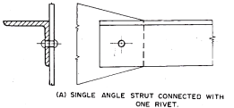
- When single angle discontinuous strut is connected to a gusset plate with one rivet as shown in Fig. 11.2.A, its effective length is adopted as center to center of intersection at each end and the allowable working stress corresponding to the slenderness ratio of the member is reduced to 80 per cent. However, the slenderness ratio of such single angle strut should not exceed 180.
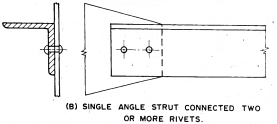
- When a single angle discontinuous strut is connected with two or more number of rivets or welding as shown in Fig. 11.2.B, its effective length is adopted as 0.85 times the length of strut center to center of intersection of each end and allowable working stress corresponding to the slenderness ratio of the member is not reduced.
Ii. Double angle strut
- A double angle discontinuous strut with angles placed back-to-back and connected to both sides of a gusset or any rolled steel section by not less than two rivets or bolts or in line along the angles at each end or by equivalent in welding as shown in Fig. A, can be regarded as an axially loaded strut. Its effective length is adopted as 0.85 times the distance between intersections, depending on the degree of restraint provided and in the plane perpendicular to that of the gusset, the effective length ‘l’ shall be taken as equal to the distance between centers of the intersections. The tacking rivets should be provided at appropriate pitch.
- The double angles, back-to-back connected to one side of a gusset plate or a section by one or more rivets or bolts or welds as show in Fig. B, these are designed as single angle discontinuous strut connected by single rivet or bolt.
If the struts carry in addition to axial loads, loads which cause transverse bending, the combined bending and axial stress shall be checked as described for the columns subjected to eccentric loading. The tacking rivets should be provided at appropriate pitch.
The tacking rivets are also termed as stitching rivets. In case of compression members, when the maximum distance between centers of two adjacent rivets exceeds 12 t to 200 mm whichever is less, then tacking rivets are used. The tacking rivets are not subjected to calculated stress.
The tacking rivets are provided throughout the length of a compression member composed of two components back-to-back. The two components of a member act together as one piece by providing tacking rivets at a pitch in line not exceeding 600 mm and such that minimum slenderness ratio of each member between the connections is not greater than 40 or 0.6 times the maximum slenderness ratio of the strut as a whole, whichever is less.
In case where plates are used, the tacking rivets are provided at a pitch in line not exceeding 32 times the thickness of outside plate or 300 mm whichever is less. Where the plates are exposed to weather the pitch in line shall not exceed 16 times the thickness of the outside plate or 200 mm whichever is less. In both cases, the lines of rivets shall not be apart at a distance greater than these pitches.
The single angle sections are used for the compression members for small trusses and bracing. The equal angle sections are more desirable usually. The unequal angle sections are also used.
The minimum radius of gyration about one of the principal axis is adopted for calculating the slenderness ratios. The minimum radius of gyration of the single angle section is much less than the other sections of same cross-sectional area. Therefore, the single angle sections are not suitable for the compression member of long lengths.
The single angle sections are commonly used in the single plane trusses (i.e., the trusses having gusset plates in one plane). The angle sections simplify the end connections.
The tee-sections are suitable for the compression members for small trusses. The tee-sections are more suitable for welding.
Q7) What is effective length?
A7) Buckling of columns are largely depends upon support conditions. In each case there is a portion of the length of the compression member bends from the points of contra flexure.
The effective length KL of a compression member is the distance between these points. Therefore, it should be derived from the actual length and end / support conditions. Tables 1 and 2 the effective length (kl) of columns and struts respectively for various end conditions.
Boundary condition | Schematic representation | Effective length | |||
At one end | At the other end | ||||
Translation | Rotation | Translation | Rotation | ||
Restrained | Restrained | Free | Free | 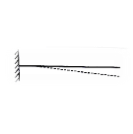 | 2.0 L |
Free | Restrained | Restrained | Free |  | 2.0 L |
Restrained | Free | Restrained | Free |  | 1.0L |
Restrained | Restrained | Free | Restrained |  | 1.2 L |
Restrained | Restrained | Restrained | Free |  | 0.8L |
Restrained | Restrained | Restrained | Restrained |  | 0.65L |
Q8) What is slenderness ratio?
A8) The tendency of a compression member to buckle is usually measured by its slenderness ratio. It is given by
Formula, 
Where,
KL= Effective length of a member
Rmin =Radius of gyration about minor axis = NA
I= Moment of inertia of a member.
The maximum slenderness ratio should be under a limit of permissible slenderness ratio of compressive member given in Table 3 of IS 800-2007.
Q9) What are types of cross section?
A9) As the compressive strength (P) decreases with increase in the slenderness-ratio, a section for the compression member should be such that it has the maximum moment of inertia for the same sectional area. So, it is preferable to choose the section having same moment of inertia about both the principle axes. Some of the sections used for compression members are shown in Fig.
Q10) Explain classification of cross section?
A10)
Cross section | Limit | Buckling about axis | Buckling class |
Rolled I section | h/bf>1.2:tf<40mm 40<mm<tf<100mm | z-z y-y z-z y-y | A B B C |
Welded I section | Tf<40mm Tf>40mm | z-z y-y z-z y-y | b c c d |
Hollow section | Hot rolled | Any | a |
| Cold rolled | Any | B |
Welded box section | Generally (expected as below) | Any | B |
| Thick welds and b/tf<30 h/tf<30 |
z-z y-y |
c c |
Channel, angle, T and Solid sections |
| Any | C |
Built up member |
| Any | c |
Q11) What is design of axially loaded compression member?
A11) To design a compression member, length, end conditions and load it has to support are required.
The designer is supposed to select a section which provides a large radius of gyration without providing more area and in which the design compressive strength (P) just exceeds the factored compressive load.
To find compressive strength, the area of cross section and radius of gyration must be known. So cut of these two unknowns, one unknown should be assumed and compute other. Then section is checked
Step (1): The design compressive stress (F) is to be assumed.
There is no proper estimation of slenderness ratio for any length and support condition, therefore for a trial, range of F for slenderness ratio given below.
(a) For Angle strut: The slenderness ratio varies from 110 to 130. Hence assume F in between 80 to 110
(b) For rolled beam sections: The slenderness ratio varies from 70 to 100. Hence assume F in between 110 to 180 MPa.
Notes: For a column with heavy factored load and large lengthy height, required large radius of gyration. Therefore, built up sections are required to the selected for design
Step (2): Selection of section:
A required= P/fcd
Step (3): Classification of section
Step (4): Knowing and conditions and determine effective length (kl). Also find out slenderness ratio.
Step (5): Determine buckling class using table 10 of IS 800-2007
Step (6): Determine design compressive stress (f)
Step (7): Determine design compressive strength P
Using Pd= Ae.fcd>P Safe
Step (8): Revise the section if P, <P (factored load) till it will safe.
Q12) What do you mean by lacing?
A12) In this case the components of the composite section are connected by lacing. Lacing consists of connecting the components of the column by a system of generally flat plates. (In some cases, angles and channels are also used as lacings). Lacing plates may be 50 mm to 75 mm wide and 8 mm to 10 mm thick.
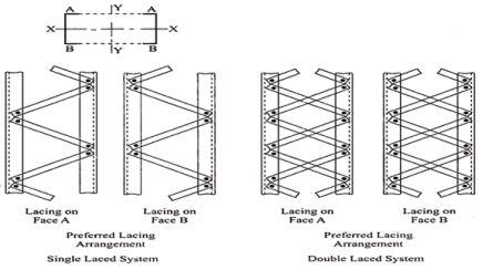
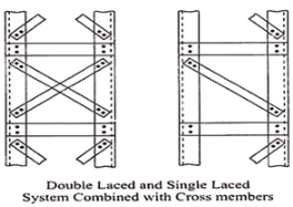
General Requirements for Lacing (IS 800):
(i) Compression members comprising two main components laced and tied, should where practicable have a radius of gyration about the axis perpendicular to the plane of lacing not less than the radius of gyration about the axis parallel to the plane of lacing.
(ii) As far as possible the lacing system shall be uniform throughout the length of the column.
(iii) Single laced systems on opposite faces of the components being laced together shall preferably be in the same direction so that one is the shadow of the other instead of being mutually opposed in direction.
(iv) The effective slenderness ratio (KL/r) e of laced columns shall be taken as 1.05 times the (KL/r) o, the actual maximum slenderness ratio, in order to account for shear deformation effects.
(v) Width of lacing bars – In bolted/riveted construction, the minimum width of lacing bars shall be three times the nominal diameter of the end bolt/rivet.
(vi) Thickness of lacing bars – The thickness of flat lacing bars shall not be less than one-fortieth of its effective length for single lacing and one-sixtieth of the effective length for double lacings.
(vii) Rolled sections or tubes of equivalent strength may be permitted instead of flats for lacings.
(viii) Angles of inclination – Lacing bars, whether in double or single or double system shall be inclined at an angle not less than 40° nor more than 70° to the axis of the built-up member.
(ix) Spacing – The maximum spacing of lacing bars, whether connected by bolting, riveting or welding, shall also be such that the maximum slenderness ratio of the components of the main member (a1/r1) between consecutive lacing connections is not greater than 50 or 0.7 times the most unfavourable slenderness ratio of the member as a whole, whichever is less, where a1 is the unsupported length of the individual member between lacing points, and r1 is the minimum radius of gyration of the individual member being laced together.
Design of Lacings:
The lacing shall be proportioned to resist a total transverse shear Vt, at any point in the member, equal to at least 2.5 per cent of the axial force in the member and shall be divided equally among all transverse lacing systems in parallel planes.
Q13) What is mean by battening?
A13) Compression members composed of two main components battened should preferably have the individual members of the same cross-section and symmetrically disposed about their major axis.
Where practicable, the compression members should have a radius of gyration about the axis perpendicular to the plane of the batten not less than the radius of gyration about the axis parallel to the plane of the batten.
The battens should be placed opposite to each end of the member and at points where the member is stayed in its length and as far as practicable, be spaced and proportioned uniformly throughout.
The number of battens shall be such that the member is divided into not less than three bays within its actual length from center to center of end connections.
The effective slenderness ratio (KL/r) c of battened columns, shall be taken as 1.1-time (KL/r) o, the maximum actual slenderness ratio of the column, to account for shear deformation effects.
Design of Battens:
Battens shall be designed to carry the bending moments and shear forces arising from transverse shear force Vt equal to 2.5 per cent of the total axial force in the whole compression member, at any point in the length of the member divided equally between parallel planes of the battens.
Battened member divided equally between parallel planes of the battens.
Battened member carrying calculated bending moment due to eccentricity of axial loading, calculated end moments or lateral loads parallel to the plane of battens, shall be designed to carry actual shear in addition to the above shear.
The main members shall also be checked for the same shear force and bending moments as for the battens.
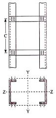
Battens shall be of plates, angles, channels or I-sections and at their ends shall be riveted, bolted or welded to the main components so as to resist simultaneously a shear Vb = (V1C)/N5 along the column axis and a moment M = (V1C)/2N at each connection.
Where,
V1 = Transverse shear force as defined above
C = Distance between center to center of battens, longitudinally
N = Number of parallel planes of battens, and
S = Minimum transverse distance between the centroid of the rivet/bolt group/welding connecting the batten to the main member.
Tie Plates:
Tie plates are members provided at the end of battened and laced members, and shall be designed by the same method as battens. In no case shall a tie plate and its fastening be incapable of carrying the forces for which the lacing or batten has been designed.
Size:
When plates are used for battens, the end battens and those at points where the member is stayed in its length shall have an effective depth, longitudinally, not less than the perpendicular distance between the centroids of the main members.
The intermediate battens shall have an effective depth of not less than three quarters of this distance, but in no case shall the effective depth of any batten be less than twice the width of one member in the plane of the battens.
The effective depth of a batten shall be taken as the longitudinal distance between outermost bolts, rivets or welds at the ends. The thickness of batten or the tie plates shall be not less than one-fiftieth of the distance between the innermost connecting lines of rivets, bolts or welds, perpendicular to the main member.
The requirement of bolt size and thickness of batten specified above does not apply when angles, channels or I-sections are used for battens with their legs or flanges perpendicular to the main member. However, it should be ensured that the ends of the compression members are tied to achieve rigidity.
Spacing of Battens:
In battened compression members where the individual members are not specifically checked for shear stress and bending moments, the spacing of battens, center to center of its end fastenings shall be such that the slenderness ratio (KL/r) of any component over that distance shall be neither greater than 50 nor greater than 0.7 times the slenderness ratio of the member as a whole about its Z-Z (axis parallel to the battens).
Q14) Explain design of columns bases?
A14) The columns are supported at the column bases. The column bases transmit the column load to the concrete or masonry basis blocks.
The column load is unfolded over massive location on concrete or masonry blocks. The depth of bearing stress on concrete or masonry is stored inside the most permissible bearing stress.
The protection of the shape relies upon up on balance of basis. The column bases need to be designed with utmost care and skill. In the column bases, depth of stress on concrete block is thought to be uniform.
The column bases will be of ok strength, stiffness and location to unfold the burden upon the concrete, masonry, different basis or different helps without exceeding the allowable strain on such basis below any mixture of the burden and bending moments.
The column bases are of types;
- Slab base
- Gusseted bases
- Slab base
The column give up is confronted for bearing over the complete area. The gussets (gusset plates and gusset angles) aren't supplied with the column with slab bases. The enough fastenings are used to hold the elements securely in plate and to withstand all moments and forces, apart from the direct compression. The forces and moments springing up all through transit, unloading and erection also are considered. When the slab by myself distributes the weight uniformly the minimal thickness of a square slab is derived as below;
Procedure
Step 1) Assume a suitable grade of concrete. Depending upon the grade of concrete used bearing strength of concrete is determine by 0.45fck
Step 2) The area of a slab base may be computed by
A= P/ bearing strength of concrete
Where,
A= area of base plate
P= Factored load
Step 3) A square base plate is generally provided. The side of the base plate may be worked out
L= B= 
Some designer feels that the projections of the base plate beyond column edges a and b are kept equal and these sides can be work out.
Using
(D+2b) x (bf+2a) = A
Where,
L= length of base plate in mm
B= width of base plate in mm
D= depth of column section in mm
Step 4) The intensity of pressure w from the concrete pedestal is determine by
W= P/A1
Where, w= intensity of pressure from concrete under the slab base
A1= Area of base plate provided in mm2
Step 5) The minimum thickness ts of the base plate is calculated by using

Step 6) Holding down bolts 2 or 4 in number and of 20 mm diameter are usually provided. When the base subjected to only axial compressive load two bolt will be enough.
Step 7) welded joint between the column and base plate is designed.
Step 8) Detailing
2. Gusseted base
Procedure
Step 1) Bearing strength of concrete is determined = 0.45 f
Step 2) Area of the base plate may be computed by,
A = P/0.45 fck
Step 3) The size of gusset base assumed
(i) Thickness: For bolted gusset base t <16 mm.
(ii) The gusset angle is chosen so as to accommodate two rows of bolts in the vertical leg and one row of bolt in the horizontal leg. Therefore, an unequal angle section is provided.
(iii) The thickness of gusset angle should be same as thickness of gusset plate.
(iv) Width of base plate.
L = depth of section + 2 (thickness of gusset plate + leg length of angle + over hang) (for bolted connections)
L = depth of section + 2x (thickness of gusset plate + overhang)
(For welded connections)
(v) Width of base plate
B = A/L
Step 4) The intensity of bearing pressure
W = P/A1
Where
A₁ = Area of base plate provided
Step 5) The thickness of the base plate is computed by equating the moment at the critical section to the moment of resistance of the gusset at that section.
B.M. At critical section
M = wc12/2(considering unit width)
Where
c.- Minimum over hang
Design bending moment at critical section M, 12

Now equating, M = Md


Where,
t= Total thickness including thickness of base plate and gusset angle (for bolted gusset base)
= Thickness of base plates (for welded gusset base)
W= Intensity of pressure from concrete under the slab faze.
C₁=Cantilever portion of base plate
Step 6) Holding down bolts 2 or 4 in numbers and of 20 diameters are usually provided.
Step 7) Design connection
Step 8) Detailing
Q15) Explain design of foundation bases?
A15) The column footings are designed to maintain the carried-out loads, moments and forces and the caused reactions.
The column load is unfolded over huge area, in order that the depth of bearing stress among the column footing and soil does now no longer exceed the secure bearing ability of the soil. It's far ensured that any agreement which might also additionally arise will be as almost uniform as viable and restrained to a typical small amount.
The column load is first transmitted to the column footing thru the column base. It is then unfolded over the soil thru the column footing. The column footings are of types;
- Independent footings
- Combined footings.
Procedure
Step 1) Transfer of axial pressure at the bottom of column
Step 2) Size of the footing
Step 3) Thickness of footing
Step 4) Minimum reinforcement
Step 5) Check for the gross base pressure
Step 6) Size of the footing
Step 7) Thickness of footing slab primarily based totally on one-manner shear
Step 8) Checking for two-manner shear