Unit - 5
Plate girder
Q1) Explain plate girder and various elements?
A1) Plate Girders:
A plate girder is a metal beam this is broadly utilized in bridge production. Depending at the layout necessities and as according to the character of the structure; steel thicknesses for internet, flanges, stiffness, and many others are decided.
The use of the right cloth (metal) having the desired electricity and doing the welding are the 2majorelements to be attended to while growing the plate girder.
A plate girder is used while we want deeper sections having better stiffness to deliver heavy hundreds.
Further, there may be an obstacle in producing a hot-rolled phase while the intensity of the phase is increased.
Therefore, we must use built-up sections which could deliver big bending moments and shear forces.
- Types of Plate Girders
There may be exclusive classifications relying at the requirements used or relying on the character of the manufacturing of the girders.
There varieties of plate girders.
1. Reverted Plate Girder
2. Welded Plate Girder
1. Reverted Plate Girder
It is an aggregate of flanges, internet, and different vital stiffness. There are related via way of means of a mechanical method, revert, and plates aren't welded collectively.
- Generally, 90% of the shear is carried via way of means of the internet.
- Connection of the internet and the flange is stabilized via way of means of the angel sections reverted to the flange. Reverts want to be designed for the horizontal shear.
- The reverts that make the relationship among the internet and flange angles want to be designed for horizontal shear and vertical hundreds that carried out to the flange after they switch to the internet.
- Angle sections are used as internet stiffness in revert girders.
2. Welded Plate Girders
Welded plate girders are maximum broadly utilized in production because of the convenience of manufacturing and its miles a far extra green sort of girder.
These sections are specifically utilized in bridge production. The plate girder bridge could be very stiff and it is able to retain very excessive hundred seven as resisting the lateral movements. This movement may be found within side the railway bridges. Further, they may be used to increase the field kind girders.
There are empirical or approximation strategies to decide the general peak of the plate girder and thickness of the flange and internet.
B. Components of Plate Girders
Mainly there are 5additives in a girder. The meeting of that 5-thing is the entire girder. The basic requirement is to make an ”I” girder having very excessive bending and shear stiffens similarly to the alternative nearby buckling resistances.
- Web Plate
- Flange
- Stiffeners (bearing, longitudinal, and intermediate)
- Splices for flange and internet
- End Connection
- Web Plate
The vertical plate of the girder is called the internet plate.
Its thickness is primarily based totally at the layout necessities and the peak can also be determined primarily based totally at the web page condition and as according to the hundreds carried out at the internet.
The internet typically includes the carried-out hundreds at the flange as shear forces. The impact of the internet isn't always usually taken into consideration while the layout for the bending.
The internet is at risk of buckling while thinner and better boom while the hundreds are carried out. Therefore, exclusive varieties of stiffness so as to be discussing on this article, are welded to the internet have its electricity.
2. Flange
There isn't any distinctiveness aside from using a separate plate for the flange. The flange plate could be welded or related via way of means of different method as mentioned beneath exclusive varieties of plate girders.
Not like rolled sections, we connect the internet and the flange collectively to shape the plate girder.
The flange is layout to hold the bending movement and stiffener or extra plate are furnished as according to the layout necessities.
3. Stiffeners
Stiffeners are furnished to enhance structural potential heading off the nearby buckling failures. In addition, they may be used to hold the hundreds carried out to the beam till it allotted into the beam.
The following varieties of stiffeners can be found in those varieties of metal elements.
- Bearing stiffeners
- Longitudinal stiffeners
- Intermediate stiffeners
The bearing stiffeners are furnished at assist to distribute the assist response to the internet with none buckling failures. There are jacking stiffness except the bearing stiffeners for installations functions as indicated within side the following figure.
Steel plates welded within side the longitudinal and the transverse instructions also are used to reinforce the internet.
The vertical or the transverse stiffeners may be typically found in maximum of the metal beams that deliver heavy hundreds.
4. Splices for Flange and Web
It is the splice connection of the internet and the flange of the girder.
When the duration of the girder is less than the span, we must have a splice connection.
This is a second and shear shifting joint which gives beam continuation.
5. End Connection
End connection is the maximum tough a part of the structural detailing of a metal beam.
When there is continuation or if we are assisting the girder to a few assists, the relationship desires to be designed accordingly.
However, maximum of the time, plate girders are saved as definitely supported on the stop assist. In such situations, we must offer the stiffeners on the stop connection.
A comparable layout system is followed while designing the endplates and the stiffener furnished vertically connecting the internet and the flange.
C. Application of Plate Girders
Plate girders are broadly used as assisting systems in exclusive regions. The following regions may be highlighted as key regions of use.
- Bridge production
Plate girders are specifically utilized in railway and avenue bridges. Mostly the antique railway bridges may be highlighted as plate girder bridges.
In addition, field girder bridges, beam bridges, navy girder composite bridges, and half – thru plate girder bridges are taken into consideration because it uses.
- Ships
- Gantry beams
- Oil and fuel line platforms
- Load testing
- Cranes
- Lifting systems
D. Advantages of Plate Girder
- They may be used to hold heavy hundreds
- Speed production
- Grater balance
- High resistance to fatigue failures
- Easy to assemble while as compared with truss kind bridges
- Easy for maintenance
E. Disadvantages of Plate Girder
- They cannot be used to assist big spans
- Less architectural appearance
- A bit tough to deal within the course of the placement
- Production will be finished strictly according with the layout.
The articles have been written on Steel Beam Design as according to BS 5950 and Steel Beam Design Worked Example [Universal Beam] could be referred for extra facts on metal beam designs.
Further facts on metal beams may be studied from the article types of metal beams.
Q2) Explain Design of components Eccentric and moment connection?
A2)
- Eccentric Connections
If the force applied does not passes through the CG of the joint then such joint carries moment in addition to an axial direct force. Such types of connections are called as eccentric connections.
Two common loading conditions are discussed in the next two sections, followed by a discussion of the generalized approach for distributing applied loads over a bolt pattern.
- In-Plane Eccentric Shear Load.
- Out-of-Plane Eccentric Shear Load.
- Generalized Approach.
- Bolt Pattern Moments of Inertia.
- Axial Forces.
- Shear Forces.
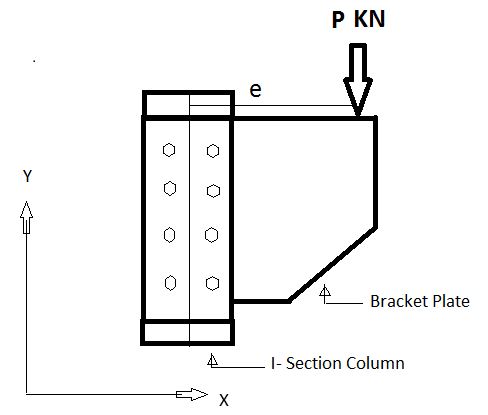
Connection subjected to eccentric shear
Seat Connections
Framed Connections
Bracket Connections
The connections are categorized as shear connections whilst the switch of load passed off via shear. Example: lap joint, butt joint
Bearing kind connections: To switch the pressure bolts undergo towards the hole
When the bolt is in double shear, cross-sections are powerful in resisting the weight. The bolt in double shear can have the two times the shear power of a bolt in unmarried shear.
2. Moment connection:
Moment resisting connections are used in multi-story un-braced buildings and in single-story portal body buildings. Connections in multi-story frames are maximum possibly to be bolted, complete intensity quit plate connections or prolonged quit plate connections. Where a deeper connection is needed to offer a bigger lever-arm for the bolts, a hunched connection may be used. However, as extra fabrication will result, this scenario ought to be averted if possible.
For portal body structures, hunched second resisting connections on the eaves and apex of a body are nearly always used, as similarly to presenting extended connection resistances, the haunch will increase the resistance of the rafter.
The maximum generally used second resisting connections are bolted quit plate beam-to-column connections; those are proven within side the parent below.
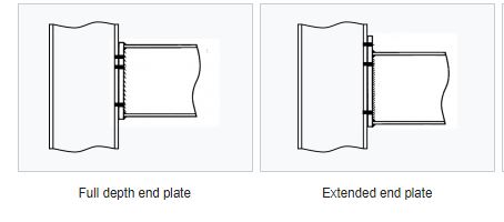
Instead of bolted beam-to-column connections, welded connections can be used. These connections can provide full moment continuity but are expensive to produce, especially on site. Welded beam-to-column connections can be prepared in the fabrication workshop with a bolted splice connection within the beam spam, at a position of lower bending moment. Welded connections are also used for the construction of buildings in seismic areas.
Other types of moment resisting connections include:
- Splices in columns and beams, including apex connections in portal frames, and
- Column bases.
Bolted beam-to-column connections
Bolted end plate joints between I-section or H-section beams and columns as shown in the figure below are designed using the approach described in BS EN 1993-1-8[1]. Bolted end plate splices and apex connections, which use similar design procedures, are covered in the section on splices.
Q3) What is roof trusses?
A3) Auditoriums, assembly halls, workshops, warehouses, industrial sheds etc. required large column free areas.
To get such areas, the commonly used roofing system is to be provided as a set of steel roof trusses, interconnected with purlins which supports GI (Galvanized Iron) or A.C. (Asbestos Cement) sheet.
A typical industrial building with its components is shown in Fig.
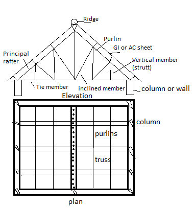
The nomenclature used for the various members of a truss are described given below
- Top chord members:
These are the members along the uppermost line of roof truss starting from one end of support to another end and passing through ridge.
These members are also called principle rafters which directly support to purlins. They are mainly subjected to axial compression due to dead loads and live loads.
If the purlins are not supported at joint, then these members are subjected to bending stresses also.
2. Bottom chord members
These are the members extending from one end of support to another end along the lowermost line of truss. These members are also known as main ties. They are mainly subjected to tensile forces due to dead loads and live loads.
3. Struts
The members which do not belong to top or bottom chord and subjected to compressive forces are called struts,
4. Slings
The members which do not belong to top or bottom chord but are mainly subjected to tension are called slings.
5. Sag tie
If no load is in the member and usually, they provided to reduce the sag in the adjacent member is called sag tie.
Types of Roof truss
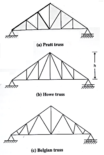
The types of roof truss depend upon the fancy of the architect and upon the demands of the particular building for which it is used. Some typical roof trusses are shown in Fig. Fink truss provided for large pitch, Pratt and Howe truss for medium pitch and warren truss provided for small pitch respectively.
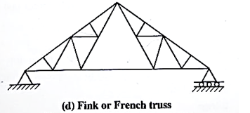
Q4) Explain geometry of roof truss?
A4)
- Pitch of truss
It is defined as the ratio of the height of truss to the span. The minimum pitch is to be maintained for G.L sheet covering is of 1/6 and for AC sheet 1/12
2. Spacing between trusses
The distance between the two consecutive trusses is called spacing of truss. As spacing of tw increases, the number of trusses may reduce cont of purlins increases. The following g may be used to decide the spacing trusses
Spacing of truss = 1/3 to 1/5 span of truss
= Span/4 (up to 20 m span)
3. Purling
As far as possible purlins should be loading panel points of top chord members However depends upon the type and length of mofag materials also. Generally, the spacing of purling varies from 1.35 to 2.0 m. Angle sections are u for smaller value of trusses (3 to 4 m) for mode sizes (4 to 5 m) channel section or I section can be preferred.
4. Central rise
Central top part of truss is called ridge time and central rise is called height of truss. Generally, it is Span/5 to Span/6 provided
5. Sheeting
(1) GI sheets: Galvanized iron sheets und protection against corrosion. The common size of GI sheet is (From 275 p Table 5)
(a) 8 corrugations 75 a 19 depth with overall width of 660 mm.
(b) 10 corrugations 75 x 19-man dog smith overall width of 810 mm
(c) Length available are 18, 22, 23, 24 and 3 m
(2) AC sheets: Asbestos cement sheets are better insulators for sun's beat compared to Gl sheet. They are used only for factories and godowns. They are available in lengths of 1.75, 2, 2.5 and 3 m.
Load calculation:
The main loads on trusses are:
- Dead loads
- Imposed loads (live loads)
- Wind load
- Other loads
- Dead load
Dead loads include the weight of roof sheeting. Purlins, bracings, self weight of truss and other loads suspended from trusses.
The unit weight of various materials is given in IS875 part I. The following values may be noted:
(a) AC sheet:
Corrugated (pitch=146 mm) = 118 to 130 N/m²
Semi-corrugated (pitch = 340 mm) = 118 to 127 N/m² Plain = 102 N/m²
(b) GI sheet: 85 N/mm²
In general, the roof covering weight including laps, connector etc. may be taken as
GI sheet: 100-150 N/m² = 130 N/m²
AC sheet: 170-200 N/m² = 180 N/m
(c) Weight of purling: 100-120 N/m²
(d) Self weight of truss for span L W 10+5) N/m² =10
Where,
S= spacing of trusses
L = span of truss
2. Imposed load (Live load)
Normally no access is provided for sloping roofs with sheets. In such cases IS 875 part II makes provision for the design of sheets and purlin are: Live load (LL): (Table-2 IS 875-part-2)
- Up to 10° slope; LL = 0.75 kN/m²
- From more than 10° slope, LL = 0.75 -0.02 (a-10)
Where a is slope of sheeting for the design of truss the above live load may be reduced to
3. Wind load
IS 875 part 3 gives guide lines to determine wind forces on different components of buildings. If consist of the following steps.
Determine basic wind speed:
(Cl.52 and Appendix A of IS 875 part 3) for finding basic wind pressure in any place in India, IS 875 part-3 divides the country into six zones. It is based on peak velocity averaged over a short time interval of about 3 seconds studied over a period of 50 years.
The values correspond to the speed at 10 m height above ground level and in an open terrain. It may be observed that highest basic wind speed is 55 m/s and the lowest is 33 m/s.