Unit - 4
Stress Distribution in Soil
Q1) Explain Boussinesq’s Equation for vertical stress?
A1)
Boussinesq Theory for Point Load:
- The problem of stress evaluation at a point inside soil mass due to point load acting on the surface of a homogeneous, elastic, isotropic and semi-infinite medium of soil mass has solved by Boussinesq)
Assumptions Made by Boussinesq:
- The soil medium is an elastic, homogeneous, isotropic and semi-infinite medium.
- The soil medium obeys Hooke's law.
- The self-weight of the soil is ignored.
- The soil is initially unstressed.
- The change in soil volume due to load application is neglected.
- The top surface of the soil is free of shear stress and only point load is acting at a point.
- Consider a point load Q acting at point O. Consider point 'S' inside soil mass where
 is acting.
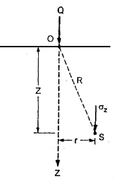
Fig.: Vertical stress due to point load
 =
=
Where r= radial distance of point S from axis of load
 = Vertical stress at point 'S'
R =Polar radial co-ordinate
The above Equation (iii) can be written as
 = KB
= KB where, KB=
KB is Boussinesq's influence factor.
Shear stress at point S due to point load Q is,
Trz= ^5/2
^5/2
The typical values of KB are as follows:
Table: Values of influence factor for r/z ratios
r/z | KB | r/z | KB | r/z | KB |
0.00 | 0.4775 | 0.40 | 0.3294 | 0.80 | 0.1386 |
0.10 | 0.4657 | 0.50 | 0.2733 | 0.90 | 0.1083 |
0.20 | 0.4329 | 0.60 | 0.2214 | 1.00 | 0.0844 |
0.30 | 0.3849 | 0.70 | 0.1762 | 2.00 | 0.0085 |
|
|
|
| 3.00 | 0.0015 |
Boussinesq's Theory for Circular Load:
- Consider the loaded circular area of radius a, 'q' is uniformly distributed load intensity on circular area. Consider elemental ring of radius 'r' and thickness dr.
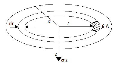
Fig.: Vertical stress on circular area
- Consider point 'P' at depth Z from the centre of loaded area.
- The vertical stress at a depth. 'Z' under the centre of circular area of diameter 'a' is,
 =
=
Q2) What is the Westergaard’s Equation?
A2)
- Boussinesq's theory for determination of vertical stress in a soil mass is for isotropic soils. But if soil deposits like sedimentary deposits are generally made up of thin layers of sand and homogeneous clay strata (i.e., anisotropic) Westergaard's theory for solution of stresses is related to such soils only. This theory is more suitable for stratified soil layers (i.e., sedimentary deposits)
Assumptions In Westergaard's theory:
- The soil mass is an elastic medium.
- The modulus of elasticity (E) of soil is constant.
- The soil mass is semi-infinite in extent i.e., boundary surface is ground level itself but extends infinitely in all other directions.
- The soil mass is anisotropic i.e., properties are not same throughout the soil mass.
The vertical stress from Fig.
 ^3/2
^3/2
Where ɳ=
- The value of 0.2 to 0.3 in above equation is quite realistic for many types of stratified soil deposits. In many cases, for practical purposes, ju is taken as zero.
 =
= KW
KW
Where, Kw is called Westergaard influence factor.
Q3) Explain Stress Distribution under loaded areas?
A3)
Pressure distribution diagram on horizontal plane:
- Consider a horizontal plane at a depth Z from point of application of load Q)
- Hence the vertical stress on horizontal plane due to point load acting at surface is
 =
=
Where  =Vertical stress on horizontal plane
Z=Depth from the point of application of load
r=horizontal distance of a point from a point load
Q = point load
Pressure Distribution Diagram on a Vertical Plane:
- Consider a vertical plane at radial distance r from a point load acting on the surface of soil mass, The equation is useful to calculate stress on a vertical plane.
e.g., Let Q= 150 KN and r=3m
 =
=
Following table gives the values of a, for different depths.
Z(m) |  |
1m | 0.295 |
2m | 0.94 |
3m | 1.407 |
4m | 1.467 |
5m | 1.328 |
6m | 1.1388 |
Q4) What is Pressure Bulb?
A4)
- Pressure bulb is also known as Isobar.
- 'Isobar' is a line or contour joining points of equal vertical stress inside soil mass.
- Isobar is a spatial curve which shows the same vertical pressure at all points in a horizontal plane at equal radial distances from the load. This stress isobar is bulb in shape hence it is called as pressure bulb. The area outside the pressure bulb is assumed to have negligible stresses. The zone within which the stresses have a significant effect on the settlement of structures is known as the pressure bulb.
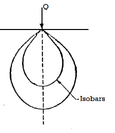
Fig.: Isobar
- The Boussinesq Equation for vertical stress due to point load is,
 =
=
- Stress isobars for different vertical stress intensity can be plotted.
Q5) What is Contact Pressure?
A5)
- The pressure transmitted from the base of a foundation to the soil is termed the contact pressure.
- This depends on the rigidity of the foundation structure and the nature of the soil.
- The pressure of a thick compressible layer like soft clay beneath a flexible foundation presents a bowl-shaped settlement profile with more settlement at the centre and almost zero at the edge.
- But the pressure distribution is uniform. This is the conventional distribution pattern used in the calculation of stresses and settlements.
- An extremely rigid footing on the same clay will settle uniform amount across its breath.
- Thus, the compressible cohesive soil under a rigid footing has to transmit high contact pressure near the edges than at the centre so as to maintain a uniform settlement.
- For a flexible foundation resting on a non-cohesive soil, the distribution of contact pressure is uniform, but the edges of the foundation experience a large settlement. Because of lack of confining pressure at the edges, the foundation settles more.
- The settlement of a rigid footing on sand layer is uniform and contact pressure increases for zero at the edge to a maximum at the centre.
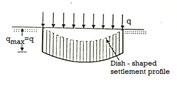
Fig.: Flexible footing on cohesive soil (Clayey soil)
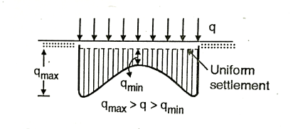
Fig.: Rigid footing on cohesive soil (clayey soil)
- In practice, no foundation is perfectly flexible nor infinitely rigid, and hence the actual distribution of contact pressure is somewhere between the extreme values.
- Sufficient accuracy in the calculation of stresses and displacements can be obtained by assuming a uniform distribution of contact pressure.
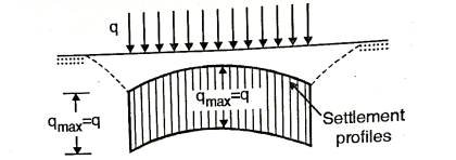
Fig.: Flexible footing on non-cohesive soil(sandy)
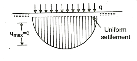
Fig.: Rigid footing on non-cohesive soil(sandy)
Q6) Explain Mohr-Coulomb Failure Criteria?
A6)
- Mainly shear failure in soil occurs by slippage of particle due to shear stress.
- Shear stress at failure normally depend upon normal stresses on the potential failure plane.
- According to Mohr soil failure is a function of normal stress applied on the soil.
i.e.,  f=f (
f=f ( )
)
 f = shear stress
 = normal stress
- The shear stress at failure is called as shear strength.
Equation (i) becomes,
 f =s= f (
 )
)
S =shear strength.
- A curve as shown is obtained when normal and shear stress corresponding to failure are plotted are called as strength envelope.
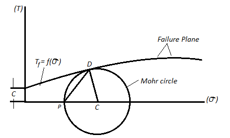
Fig.: Mohr’s Theory
Columb later modified Mohr’s equations and gave the following equation.
S=c+ 
∴Thus, Mohr envelope is replaced by straight Line
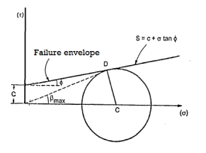
Fig.: Mohr’s coulomb envelope
We can say that c is intercept on c axis and is angle made by envelope with  axis. The component 'c' of shear strength is called as cohesion which is independent of normal stress which hold soil particle together and d-represent angle of internal friction. Failure occurs when Mohr circle touches failure envelope or one can say at a maximum obliquin (Bmax) in which resultant touches Mohr circle and when
  and c gives a critical combination failure occurs.
In case where c=0 the graph starts from origin and equation becomes.
S= 
In case where =0 i.e., friction less or fully cohesive soil the line will be horizontal. Later it will be found that c and depends upon number of factors like water content drainage conditions and lasting condition. Thus, Terzaghi shows that the effective stress controls the shear strength and hence the equation gets modified
:. s = c’+tan
c' =Effective cohesion intercept
 Effective angle of shearing resistance
 = Effective stress
This above equation is called as Mohr Coulomb equation for shear strength of soil.
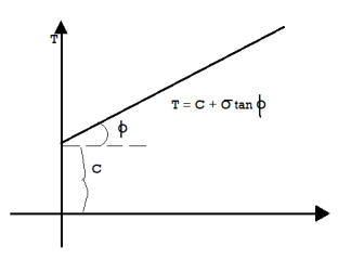
Fig.: Soil with internal friction and cohesion
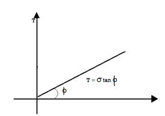
Fig.: Cohesionless soil
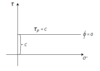
Fig.: Frictionless soil
Q7) Explain Direct shear test?
A7)
- This is the oldest shear test method in use and still most common because of its simplicity. It is also known as shear box test.
- The soil specimen is confined in a metal box that is split horizontally.
- If the specimen is fully or partially saturated, perforated metal plates and porous stones are placed above and below the specimen for drainage.
- If the specimen is dry, solid metal plates are used.
- A pressure pad is placed on top and the entire box is placed in a trolley.
- The upper half of the box is fixed to a support through a proving ring and the lower half of the box is pushed at a constant rate of strain. A vertical load is applied on the pressure pad. At time of failure, shear stress is measured by the proving ring.
- Then the test is repeated for another sample of the same soil, for a different vertical load on the pressure pad.
- 4-5 repetitions are made for 4-5 different normal loads. By dividing normal load and corresponding shear load at failure by the internal horizontal area of the shear box, the normal and shear stress values can be obtained.
- These values are plotted and a best fit straight line through these points gives the strength envelope. From this C and
 can be determined.
 - The arrangement is shown in Fig.

Fig.: Test arrangement
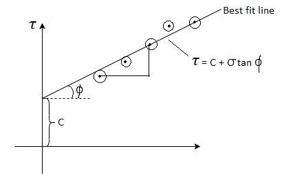
Fig.: Graph of direct shear test
- Thus, the direct shear test is the most commonly used test as it has following advantages.
Advantages and Disadvantages of Direct Shear Test:
Advantages:
- Test is simple and fast.
- Drainage is quick due to less thickness of sample.
- CD and CU tests takes relatively small period, because of quick drainage and rapid dissipation of pore water pressure.
- Test is ideally suited for drained tests on cohesionless soils.
- The direct shear test apparatus is relatively cheap.
Disadvantages:
- Failure of soil specimen is always along a horizontal plane, which may not be very realistic.
- If any large soil particles or stones etc. are present at failure plane, it will give wrong results.
- Actual field condition is not simulated in the set up.
- Measurement of pore pressure is not possible.
Q8) Explain Triaxial Compression test?
A8)
- A Casagrande invented the triaxial compression test so as to remove the disadvantages of the direct shear test. The triaxial compression test is most efficient and versatile of all the shearing testing methods of any type of soil. In this method, drainage condition can be controlled. Pore water pressure can be measured accurately and also volume changes can be measured with the help of triaxial test.
- Fig. Shows the triaxial cell in which the soil sample is subjected to confining pressure (
 ) by applying pressure to water in the cell. Note that there is no rotation of the principal stresses during the test and the failure plane is not forced. The soil sample can fail on any weak plane or can simply bulge. In short, the soil sample may subject to brittle failure or plastic failure.
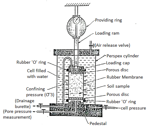
Fig.: Triaxial cell
- The triaxial test is carried out on a cylindrical sample er specimen of soil which is being taken securely in the rubber membrane. Cylindrical specimen of soil having a length to diameter ratio as 2. The usual sizes of specimen of soil are 76 x 38 mm or 100 x 50 mm.
- The triaxial test apparatus consists of the following components:
- Loading frame
- Proving ring
- Pressure apparatus
- Loading arm
- Porous disc
- Triaxial cell
- Pressure chambers
- Sample trimmer
- Rubber 'O' ring
- Air release value
- Triaxial cell is a Perspex cylinder which is attached to the base with rubber seals so as to make the cell water tight. The pressure cylinder controls the constant pressure in the triaxial cell. Sometime a separate compressor is used to apply fluid pressure in the cell. There is a separate pore pressure means equipment which measure the pore pressure developed in the soil specimen during test. Cylindrical soil specimen is enclosed in a rubber membrane.
- A stainless-steel piston running through the centre of the top from which the vertical compressive load (deviator stress) can be applied on the soil specimen under test.
- Porous discs are placed on the top and bottom of the soil specimen and rubber membrane is sealed by rubber 'O' ring depending upon the drainage conditions of the test.
Test procedure:
Following are the various points which explains the test procedure.
- The cylindrical specimen is kept on a saturated porous disc resting on the pedestal of the triaxial cell.
- The cylindrical specimen is enclosed by a rubber membrane and sealed at the top and bottom by rubber 'O' ring. The rubber membrane prevents the penetration of water into the soil specimen.
- The triaxial cell is filled with water at the required pressure through cell pressure unit. This water pressure is subjected to the soil specimen to all-around. This water pressure is called as cell pressure or the confining pressure (
 )). Cell pressure acts radially on the vertical surface of the specimen and axially at the top and bottom.
 - By keeping constant cell pressure, additional axial stress is applied through the ram gradually until the soil specimen fails. This t additional axial stress is also called as deviator stress produces shear stresses within the soil sample on all planes except the horizontal and vertical planes.
Fig. Shows the principal stresses on the triaxial specimen
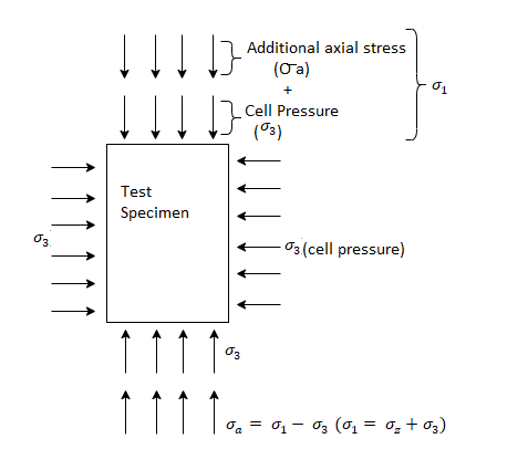
Fig.: Principal stress on the triaxial specimen
In the first stage, cell pressure ( )) is applied on the test specimen and in the second stage, deviator stress (ie. Additional axial stress,
  ) is applied on the sample until the failure of the soil specimen.
 =deviator stress (
 )+cell pressure (
 )
)
 =
= -
-
5. During triaxial loading, outlet valve of drainage burette is kept open so as to have the result for drained loading. This outlet valve is kept closed for an undrained loading.
6. The drainage burette or drainage outlet is connected to the pore pressure apparatus by which pore pressure can be measured.
7. The drainage burette is also connected to the volume measuring apparatus so as to measure change in volume for drained loading.
Advantages of Triaxial Test:
Following is the various advantage of triaxial test
- A Casagrade developed the triaxial test in his research and removed the disadvantages of direct shear test.
- There is a complete control during conducting the shear test under all the three drainage conditions.
- Porewater pressure and volume change are precisely measured during the test.
- There is uniform stress distribution on the failure plane.
- State of stress within the soil sample during any stage of the test and at the failure of soil sample is completely determinate.
Disadvantages of Triaxial Test:
- The apparatus in triaxial test is bulky, costly and elaborate.
- Triaxial test takes longer period in case of drained test as compared with that in a direct shear test.
Q9) Explain unconfined Compression test?
A9)
- This test is especially useful for homogenous cohesive clayey soils. It cannot be used for dry.
- In this test, a cylindrical soil specimen is fitted between two plates, with slight conical projections for firm grip on the specimen, and a compressive axial stress is applied on it till it fails.
- Since the test is quick, water is not allowed to drain out from the specimen, hence it is an undrained test. If qu, is the stress at failure, then the shear strength is given as,
 f=Cu=qu/2
- The arrangement is shown in Fig. The Mohr's circle in this case is drawn and the various parameters are shown.
- Internal friction is assumed to be zero as this test can be used only for purely cohesive soils.
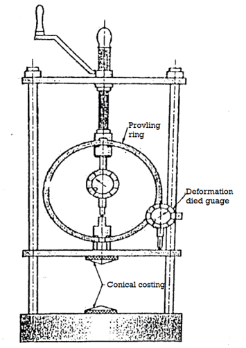
Fig.: Test arrangement
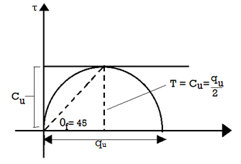
Fig.: Mohr’s circle
Advantages of Unconfined Compression Test:
- It is quick and convenient for meaning shear strength.
- It is useful for homogeneous cohesive clayey soil.
- It is suitable for measuring unconsolidated, undrained shear strength of saturated class
- It is used to measure in situ strength and very useful for field test.
Disadvantages of Unconfined Compression Test:
- This test cannot be carried out on coarse grained soils like sands and gravels and also not carried out on fissured clays.
- The test result may be misleading for the soils for which
 0.
0.
Q10) What is Soil Liquefaction?
A10)
- Soil liquefaction, additionally known as earthquake liquefaction, floor failure or lack of power that reasons in any other case stable soil to act briefly as a viscous liquid.
- The phenomenon happens in water-saturated unconsolidated soils suffering from seismic S waves (secondary waves), which reason floor vibrations at some stage in earthquakes.
- Although earthquake surprise is the excellent acknowledged reason of liquefaction, sure creation practices, which include blasting and soil compaction and vibroflotation (which makes use of a vibrating probe to alternate the grain shape of the encircling soil), produce this phenomenon intentionally.
- Poorly tired fine-grained soils including sandy, silty, and gravelly soils are the maximum at risk of liquefaction.
- Granular soils are made of a combination of soil and pore areas. When earthquake surprise happens in waterlogged soils, the water-crammed pore areas collapse, which decreases the general quantity of the soil.
- This technique will increase the water strain among character soil grains, and the grains can then flow freely withinside the watery matrix. This extensively lowers the soil’s resistance to shear strain and reasons the mass of soil to take at the traits of a liquid. In its liquefied state, soil deforms without difficulty, and heavy gadgets including systems may be broken from the unexpected lack of guide from below.
- Buildings built on unfastened soil pitch and tilt without difficulty while liquefaction happens, for the reason that soil now not helps the systems’ foundations.
- In contrast, systems anchored to bedrock or stiff soils in earthquake-susceptible regions go through much less damage, due to the fact much less vibration is transmitted thru the muse to the shape above. In addition, homes anchored to bedrock have a discounted threat of pitching and tilting.
Q11) A concentrated load of 40 KN is applied vertically on ground surface. Determine the vertical stress intensities at the following points:
1)At a depth of 3m below the point of application of the load.
2)At a depth of 1m and at a radial distance of 3m from the line of action of load.
A11)
1) Given: Z=3m, Q=40KN
Here r=0 due to stress intensity below the point of application of load.
To find stress intensity ( )
)
Using Boussinesq’s equation as,
 =
=
=
∴
2)To find stress intensity at a depth of 1m and at a radial distance of 3m from the load
Here Z=depth=1m and r=radial distance=3m
Using Boussinesq’s equation as,
 =
=
=

Q12) A concentrated load of 100 kN acts on the surface of homogenous soil mass of large extent. Find the stress intensity at a depth of 4 meters directly under the load. Use Bossinesq’s equation.
A12)
Given:
Q=100KN
Z=depth=4m
Since the stress intensity is directly under the load, r=0
To find stress intensity ( ) by Bossinesq’s equation,
 =
=
=

Q13) A concentrated load of 300KN is applied at the ground surface. Compute the vertical pressure.
1)at a depth of 6m below the load
2)at a distance of 5m at the same depth
A13)
Given:
Q=300KN, z=6m, r=5m
1. To compute the vertical pressure at a depth of 6m below the load:
Using Boussinesq’s equation as,
 =
=
Since the stress intensity directly below the load, r=0
=

2.To compute vertical stress at a horizontal distance of 5m
Here z=6m, and r=5m
 =
=
=

Q14) A load of 1000KN acts as a point load at the surface of a soil mass. Estimate the stress at appoint 3m below and 4m away from the point of action of the load by Bossinesq’s formula. Compare the value with the result from westergaard’s theory.
A14)
Given:
Q=load=1000KN
Z=3m, r=4m
1. As per Boussinesq’s theory


2. As per Westergaard theory:


