Unit - 3
Pipeline and superscalar techniques
Q1) Explain linear pipeline processors?
A1) Linear pipelining is a method of decomposing any sequential process into small, distinct subprocesses such that each subprocess can be implemented in its own dedicated segment and all of these segments can work at the same time. As a result, the entire function is divided into subtasks, each of which is carried out by a segment.
Pipelining is a computer architecture concept that corresponds to a technical assembly line. A product is made by the manufacturing division, while it is packed by the packaging division, and a new product is manufactured by the manufacturing unit, as there are various divisions in the market such as production, packing, and delivery.
Pipelining in a straight line Pipelining is a technique for decomposing any sequential operation into small, independent subprocesses so that each subprocess can be executed in its own dedicated segment and all of these segments can run at the same time. As a result, the entire task is divided into distinct tasks, each of which is carried out by a segment. The output of a segment (after executing all computations in it) is sent to the next segment in the pipeline, and the ultimate result is produced when the data has passed through all segments. As a result, if each segment consists of an input register followed by a combinational circuit, it would be understandable.
The needed sub operation is performed by this combinational circuit, and the intermediate result is stored in a register. The output of one combinational circuit is fed into the following section as an input. Pipelining is a computer organizing idea that is similar to an industrial assembly line. A product is made by the manufacturing division, while it is packed by the packing division, and a new product is manufactured by the manufacturing unit, since there are different divisions in industry such as production, packing, and delivery. A third product is being created by the production unit while this product is being delivered by the delivery unit, and the second product has been packed.
As a result of the pipeline, the total process is sped up. Pipelining is most successful for systems that have the following characteristics:
● A system performs a basic function over and over again.
● A basic function must be divided into discrete stages with little overlap between them.
● The phases' complexity should be relatively comparable.
The flow of information is what pipelining in computer organization is all about. Consider a process that has four steps/segments and needs to be repeated six times to understand how it works for the computer system.
If each step takes t nsec, then it will take 4 t nsec to finish one procedure, and 24t nsec to repeat it six times. Now let's look at how the problem behaves when using the pipelining concept. This is demonstrated in the space-time diagram below, which depicts segment use as a function of time. Consider the following scenario: There are six processes to be managed (shown in the diagram as P1, P2, P3, P4, P5, and P6), each of which is divided into four segments (S1, S2, S3, S4). For the sake of simplicity, we assume that each segment takes the same amount of time to complete the assigned task, i.e., one clock cycle. The horizontal axis shows the time in clock cycles, while the vertical axis shows the number of segments. Process1 is initially handled by segment 1. After the first clock segment 2, process 1 is handled by segment 2, while new process P2 is handled by segment 1.
As a result, the first process will take four clock cycles, and the subsequent operations will be finished one at a time. As a result, the total time necessary to finish the operation in the previous example will be 9 clock cycles (with pipeline organization) rather than the 24 clock cycles required in the non-pipeline version.
1 2 3 4 5 6 7 8 9
P1 S1 S2 S3 S4
P2 S1 S2 S3 S4
P3 S1 S2 S3 S4
P4 S1 S2 S3 S4
P5 S1 S2 S3 S4
P6 S1 S2 S3 S4
Fig 1: Space Timing Diagram
Q2) Explain asynchronous and synchronous model?
A2) With k processing stages, a linear pipeline processor is built. At the first stage S1, external inputs (operands) are fed into the pipeline. The processed results are passed from stage Si to stage Si+i, and at step Sn, the final output emerges from the pipeline. We categorize linear pipelines into two types based on the control of data flow through the pipeline: asynchronous and synchronous.cking division, a new product is made by the manufacturing unit.
Asynchronous Model
A handshaking protocol controls data flow between neighboring stages in an asynchronous pipeline, as depicted in the diagram. Stage Si transmits a ready signal to stage Si+1 when it is ready to transmit. After receiving the data, stage sends an acknowledgement signal to Si. In message-passing multi-computers where pipelined wormhole routing is used, asynchronous pipelines are useful in creating communication channels. The throughput rate of asynchronous pipelines might be varied. At different stages, different amounts of delay may be encountered.

Fig 2: Asynchronous model
Synchronous Model
Figure depicts synchronous pipes. Interfacing between stages is done with clocked latches. The latches are constructed using master-slave flip flops, which may separate inputs from outputs. When a clock pulse is received, All latches send data to the next step at the same time. Combinational logic circuits are used in the pipeline phases. In all stages, it is desirable to have about equal delays. The clock period and consequently the pipeline speed are determined by these delays. Only synchronous pipes are investigated unless otherwise stated. A reservation table specifies the pattern of consumption of subsequent stages in a synchronous pipeline.

Fig 3: Synchronous model
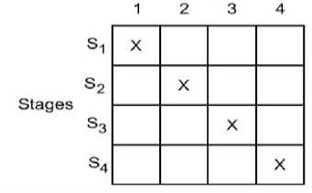
The use of a linear pipeline follows the diagonal streamline pattern seen in Fig. The precedence relationship in employing the pipeline phases is depicted in this table, which is effectively a space-time diagram. To enter the pipeline, successive tasks or operations are started one at a time. When the pipeline is full, one result emerges from the pipeline for each subsequent cycle. Only if the jobs are independent of one another can this throughput be maintained.
Clocking and Timing Control
A pipeline's clock cycle is calculated as follows. Let T* be the circuitry's time delay in stage Si, and d be the latch's time delay.
Clock Cycle and Throughput: Denote the maximum stage delay as Tm ,and we can write T as T = max{Ti} + d =Tm+d
The data is latched to the master flip-flops of each latch register at the rising edge of the clock pulse. The width of the clock pulse is equal to d. T m »d for one to two orders of magnitude in general. This means that the clock period is dominated by the greatest stage delay Tm. The inverse of the clock period is used to calculate the pipeline frequency.
If the pipeline is intended to produce one result per cycle, f denotes the pipeline's maximum throughput. The actual throughput of the pipeline may be lower than f, depending on the rate at which consecutive tasks enter the pipeline. This is due to the fact that more than one clock cycle has passed between job initiations.
Clock Skewing: The clock pulses should ideally arrive at all stages (latches) at the same time. The same clock pulse may arrive at different stages with a temporal offset of s due to a problem known as clock skewing.
Let tmax be the time delay of the stage's longest logic path, and tm be the time delay of the stage's shortest logic path.
To avoid a race in two successive stages, we must choose Tm > tmax + s and d < tmn — s. These constraints translate into the following bounds on the clock period when clock skew takes effect: d + tmax +s <= T<= Tm+tmin-s Tn the ideal case s = 0, tmax = Tm, and tmin = d. Thus, we have T=Tm+ d Speedup, Throughput & Efficiency of Pipeline:
Speedup is defined as

Assume a function with k stages of equal complexity and a duration T of the same length. For one input, a non pipelined function will require kT time. Then T = nk/ (k+n-1)T = nk/ (k+n-1)T = nk/ (k+n-1)
Efficiency - Efficiency is a measure of how well the pipeline's resources are used. When a stage is available for a set amount of time, its availability becomes the resource unit. Efficiency can be described as the ability to perform tasks efficiently.

No. Of used stage time units = nk there are n inputs and each input uses k stages.
Total no. Of stage-time units available = k[ k + (n-1)]
Throughput: It is the average number of results computed per unit time. For n inputs, a k-staged pipeline takes [k+(n-1)]T time units Then, Throughput = n / [k+n-1] T = nf / [k+n-1] where f is the clock frequency.
Q3) Explain reservation and latency analysis?
A3) A dynamic pipeline can be changed to perform different functions at various times. Because they are employed to perform fixed functions, classic linear pipelines are static pipelines. In addition to streamlining connections, a dynamic pipeline provides for feedforward and feedback connections.
Reservation and Latency analysis
It is simple to split a given function into a sequence of linearly ordered sub functions in a static pipeline. However, because the pipeline stages are associated with loops in addition to streamlining connections, function partitioning in a dynamic pipeline becomes extremely complicated. Figure depicts a multifunctional dynamic pipeline.
There are three steps to this pipeline.
A feedforward link from S1 to S3 and two feedback connections from S3 to S2 and S3 to S1 are available in addition to the streamline connections from S1 to S2 and S2 to S3. The scheduling of subsequent events within the pipeline is complicated by these feedforward and feedback links. With these links, the pipeline's output isn't always from the final stage. In reality, if alternative data flow patterns are followed, the same pipeline can be used to evaluate several functions.

Fig 4: Three stage pipelines
Reservation table
Reservation Tables: In a static linear pipeline, the reservation table is simple because data flows in a straight path. Because a nonlinear pattern is followed, the reservation table for a dynamic pipeline becomes more interesting. Multiple reservation tables can be established for the evaluation of different functions based on a pipeline setup. In Figure, two reservation tables are shown, one for function X and the other for function Y.

Fig 5: Reservation table
One reservation table is used for each function evaluation. A single reservation table defines a static pipeline. More than one reservation table can specify a dynamic pipeline. Each reservation table depicts the data flow through the pipeline in time and space for a single function evaluation. On the reservation table, different functions may take different pathways.
The same reservation table might be used to represent a variety of pipeline layouts. Between multiple pipeline designs and different reservation tables, there is a many to many mapping. The evaluation time of a function is defined as the number of columns in a reservation table.
Latency analysis
The latency between two pipeline initiations is the amount of time units (clock cycles) between them. Values for latency must be non-negative integers. A delay of k indicates that k clock cycles separate two initiations. A collision will occur if two or more initiations attempt to use the same pipeline stage at the same time. A pipeline collision occurs when two initiations compete for resources. As a result, while scheduling a succession of pipeline initiations, all collisions must be avoided. Some latencies induce collisions, whereas others do not. The term "forbidden latencies" refers to latencies that induce collisions.
Q4) Describe Collision free scheduling?
A4) The basic goal of event scheduling in a nonlinear pipeline is to achieve the shortest average latency between initiations without incurring collisions. We will offer a systematic strategy for obtaining such collision-free scheduling in the following sections.
Collision vector
The set of allowed latencies can be distinguished from the set of restricted latencies by looking at the reservation table. The maximum permitted latency in m=n-1 for a reservation table with n columns. The maximum latency p that can be tolerated should be as low as possible. In the range 1=p=m-1, the choice is made. The ideal case corresponds to an allowed latency of p = I.
State Diagram
Based on the collision vector, specifies the allowable state transitions between subsequent initiations.
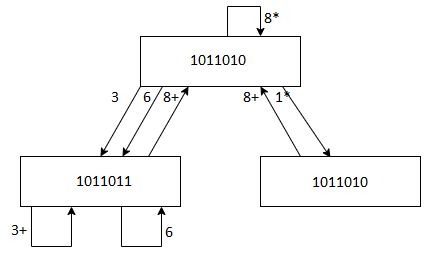
The state diagram's minimum latency edges are indicated with an asterisk.
Simple Cycle, Greedy Cycle and MAL - A Simple Cycle is a latency cycle with only one appearance of each state. Only (3), (6), (8), (1, 8), (3, 8), and (6, 8) are simple cycles in the preceding state diagram. The cycle (1, 8, 6, 8) is not straightforward because it passes through the state two times (1011010).
A Greedy Cycle is a basic cycle in which all of the edges are constructed with the shortest possible time from their respective beginning states. The greedy cycles (1, 8) and (3) are the most common.
The minimum average latency obtained from the greedy cycle is known as MAL (Minimum Average Latency). The cycle (3) leads to MAL value 3 in greedy cycles (1, 8) and (3).
Q5) What is pipeline scheduling optimization?
A5) The process of gathering instructions from the processor through a pipeline is known as pipelining. It provides for the systematic storage and execution of instructions. Pipeline processing is another name for it.
Pipelining is a method of executing many instructions at the same time. The pipeline is divided into stages, each of which is joined to the next to form a pipe-like structure. Instructions come in from one end and leave from the other.
Pipelining improves the total flow of instructions.
Each segment of a pipeline system is made up of an input register followed by a combinational circuit. The register is used to store data, and the combinational circuit manipulates it. The output of the combinational circuit is applied to the next segment's input register.
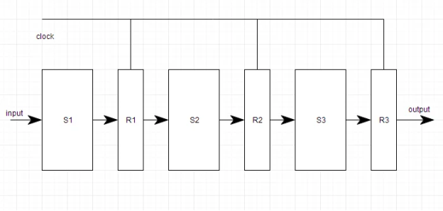
Fig 6: Pipeline system
A pipeline system is similar to a factory's modern assembly line setup. For example, in the automobile sector, massive assembly lines are built up with robotic arms performing specific tasks at each stage, and the car then moves on to the next arm.
Pipeline conflicts
Some variables cause the pipeline's performance to diverge from its regular state. The following are some of these factors:
Time variation
It is impossible for all steps to take the same amount of time. This problem is most common in instruction processing, because different instructions require different operands and hence take variable amounts of time to process.
Data Hazards
When numerous instructions are partially executed and they all relate to the same data, a problem occurs. We must make sure that the next instruction does not try to access data before the present one, as this will result in inaccurate results.
Branching
We need to know what the next instruction is in order to fetch and execute it. If the current instruction involves a conditional branch, the result of which will lead us to the next instruction, the next instruction may not be known until the current one is completed.
Interrupts
Unwanted instructions are inserted into the instruction stream by interrupts. Interrupts have an impact on how instructions are carried out.
Data dependency
It occurs when a subsequent instruction is dependent on the outcome of a preceding instruction, but the latter is not yet available.
Q6) Describe instruction pipeline design?
A6) A processor that executes separate instructions relating to a process in its various stages is known as an instruction pipeline processor.
A pipeline can execute a stream of instructions in an overlapping way.
Instruction execution phase
The phases are suitable for overlapping the execution of a linear pipeline; depending on the instruction type and processor/memory architecture, each phase may take one or more clock cycles to complete.
● Fetch stage - Instrs are retrieved from a cache memory, ideally one every cycle.
● Decode stage - determines the resources required to perform the instr function. Registers, buses, and Functional Units are examples of resources.
● Issue stage - Operands are read from registers, and resources are reserved.
● Execute stage - Instr's can be executed in one or more phases.
● Write back - To write results into registers, stage is utilized.

Fig 7: Seven stage instruction pipeline
Mechanism for instruction pipelines
Prefetch buffer - To match the instruction fetch rate to the pipeline consumption rate, three types of buffers can be used. As shown in figure, a block of consecutive instructions is fetched into a prefetch buffer in one memory access time. As shown in the MIPS R4000, block access can be accomplished utilizing an interleaved memory module or by using a cache to reduce the effective memory access time.
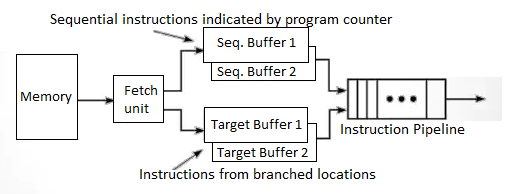
Fig 8: Prefetch buffer
For in-sequence pipelining, sequential instructions are loaded into a pair of sequential buffers. For out-of-sequence pipelining, instructions from a branch target are fed into a pair of target buffers. Both buffers work on the first-in-first-out principle. These buffers become part of the pipeline as additional stages.
For in-sequence pipelining, sequential insts are loaded into a pair of sequential buffers.
For out of sequence Pipelining, the instr's from Branch target are loaded into a pair of target buffers.
A conditional branch instr causes instr to fill both sequential and target buffers. Following the branch condition check, the appropriate instruction will be retrieved from one of the two buffers, and the instruction in the other buffer will be discarded.
One buffer from each pair can be used to load instrs from memory, while the other can be used to feed instrs into the pipeline, preventing collisions between instrs going IN and OUT of the pipeline.
Loop Buffer - keeps a loop of consecutive instrs. Fetch Stage is in charge of keeping it up to date.
In a loop body, pre-fetched instr's will be run until all iterations are completed.
Loop Buffer works in two stages:
First, it holds instrs that are sequentially ahead of the present instr, which saves time retrieving instrs from memory. It detects when a branch's goal is within the loop boundary. If the destination instruction is already in the loop buffer, unwanted memory accesses can be avoided.
Internal data forwarding
To save time, memory access procedures can be substituted with register transfer operations.
Store Load Forwarding
Because register transfer is faster than memory access and reduces memory traffic, the load operation (LD R2,M) from memory to register R2 can be substituted by the move operation (MOVE R2,R1) from register R1 to R2, resulting in a reduced execution time.
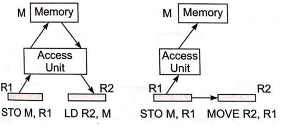
Fig 9: Store - load forwarding
Load-Load Forwarding
We can replace the 2nd load operation (LD R2,M) with a move operation (MOVE r2, R1).

Fig 10: Load-load forwarding
Multiple Functional Units
A certain pipeline stage becomes a bottleneck - this stage corresponds to the reservation table row with the most checkmarks.
Multiple copies of the same stage can be solved at the same time, i.e., employing multiple execution units in a pipelined processor design.
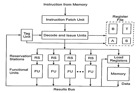
Fig 11: Multiple functional units
FIG - Tagging is used to support a pipelined processor with many FUs and dispersed RSs.
● Reservation Stations (RS) are utilized with each functional unit to resolve data or resource dependencies among subsequent instructions entering the pipeline.
● In RS, operators wait for data dependencies to be addressed.
● Each RS is recognized by a Tag that is monitored by a tag unit.
● Tag unit continuously checks tags from all currently used registers or RS's.
● RS also act as buffers to connect pipelined functional units to the decode and issue unit.
● Once dependencies are addressed, many functional units can work in parallel.
Hazard avoidance
If instructions in a pipeline are run out-of-order, the read and write of shared variables by separate instructions may result in different outputs.
There are three types of logic risks that can occur. As seen in the diagram below:
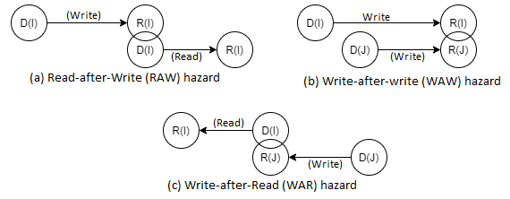
Fig 12: Hazards
Take, for example, instrs I and J, with J considered to logically follow instr I in program order.
If the order in which these two instructions are executed differs from the program order. Wrong - results could be read or written incorrectly, posing a risk.
- Hazards should be avoided before these instructions are sent down the pipeline, for example, by deferring instruction J until the dependency on instruction I is addressed.
- D is the domain of instr –input set D(I) and D is the domain of D is the domain of D is the domain of D is the domain of D is the domain of D is the domain of (J).
- R is the instr – output set range.
Q7) Explain arithmetic pipeline design?
A7) Because digital computers use fixed-size memory words or registers, arithmetic is executed with finite precision.
● Fixed-point or integer arithmetic allows you to work with a limited amount of numbers. Floating-point arithmetic has a significantly wider dynamic range of numbers than traditional arithmetic.
● Fixed-point and floating-point arithmetic operations are frequently handled by distinct circuitry on the same processing chip in modem processors.
Fixed point operations
● Internally, machines represent fixed-point numbers using sign-magnitude, one's compliment, or two's compliment notation.
● Because of its unique representation of all integers, most computers employ the two's complement notation (including zero).
● The four basic arithmetic operations are add, subtract, multiply, and division.
● When two n-bit integers (or fractions) are added or subtracted, the output is an n-bit integer (or fraction) with at most one carry-out.
● When two n-bit values are multiplied, the result is 2n-bit, requiring two memory words or two registers to carry the full-precision result.
● In fixed-point division with rounding or truncation, only an approximate result is expected.
Floating Point Numbers
A pair (m, e) represents a floating-point number X, where m is the mantissa and e is the exponent with an inferred base (radix). X=m* is the algebraic representation of the value.
The X symbol can be found in the mantissa.

Fig 13: Floating-point standard
With r = 2, a binary base is assumed. An extra – 127 code is used in the 8-bit exponent e field. (-127, 128) is the dynamic range of e, which is internally represented as (0, 255). A 25-bit sign-magnitude fraction is formed from the sign s and the 23-bit mantissa field m, which includes an implicit or "hidden" l bit to the left of the binary point. As a result, the entire mantissa represents the binary value 1.m.
The number does not contain this hidden bit. In the case of 0<e< 255, a nonzero normalized number represents the algebraic value:

Static Arithmetic Pipelines
Fixed-point and floating-point operations are performed separately by the arithmetic/logic units (ALUs).
- The integer unit is another name for the fixed-point unit.
- The floating-point unit can be integrated into the main processor or run on its own coprocessor.
Scalar operations involving one pair of operands are performed by these arithmetic units. As well as vector operations. The key differences between a scalar and a vector arithmetic pipeline are the register files and control mechanisms involved.
Vector hardware pipelines are frequently implemented as add-ons to scalar processors or as an attached processor controlled by a control processor.
Arithmetic Pipeline Stages:
Because all arithmetic operations (such as add, subtract, multiply, divide, squaring, square rooting, logarithm, and so on) may be implemented with the basic add and shift operations, the core arithmetic stages require hardware to add and shift.
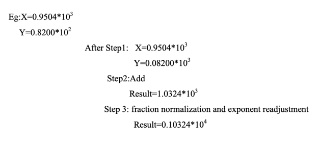
A common three-stage floating-point adder, for example, has the following stages:-
1. An integer adder and some shifting logic are used in the first stage for exponent comparison and equalization;
2. A high-speed carry lookahead adder is used in the second stage for fraction addition.
3. And a third stage employing a shifter and more addition logic for fraction normalization and exponent correction. (To obtain a non-zero number after fraction, shift the mantissa to the right and increase the exponent by one.)
● Shift registers can simply implement arithmetic or logical shifts.
● High-speed addition necessitates the use of a carry-propagation adder (CPA), which adds two numbers and provides an arithmetic sum, as shown in Fig. a below, or the use of a carry-propagation adder (CPA) that adds two numbers and produces an arithmetic sum, as shown in Fig. b below.
○ Using ripple carry propagation or any carry lookahead technique, the carries created in succeeding digits are allowed to travel from the low end to the high end in a CPA.
● or, as shown in Fig. b. Below, using a carry-save adder (CSA) to three input integers to create one sum output and one carry output.
○ The carries in a CSA are not permitted to propagate and are instead saved in a carry vector.
e.g., n=4
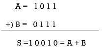
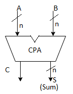
(a) An n-orbit carry-propagate adder (CPA) which allows either carry propagation or applies the carry-lookahead technique
e.g., n=4
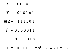
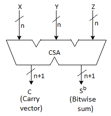
Fig 14: Carry propagate adder and carry save adder
(b) An n-orbit carry-save adder (CSA), where  is the bitwise sum of X, Y, and Z and C is a carry vector generated without carry propagation between digits.
Multiply Pipeline Design
Consider the multiplication of two 38-bit integers as an example. P is the 16-bit product, hence AxB = P. As seen below, this fixed-point multiplication can be represented as the sum of eight partial products: P = A x B = P0 + P1 + P2 +.....+ P7, where x and + denote the arithmetic multiply and add operations, respectively.
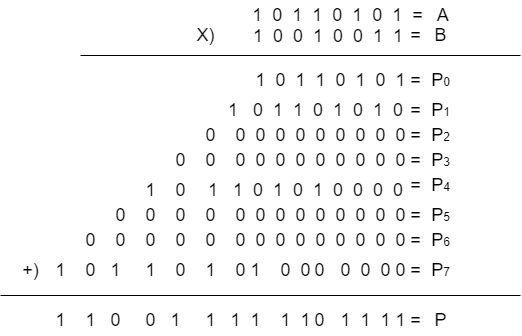
At the last stage, a Wallace tree of CSAs plus a CPA is used to total the eight partial products, as shown in Fig.
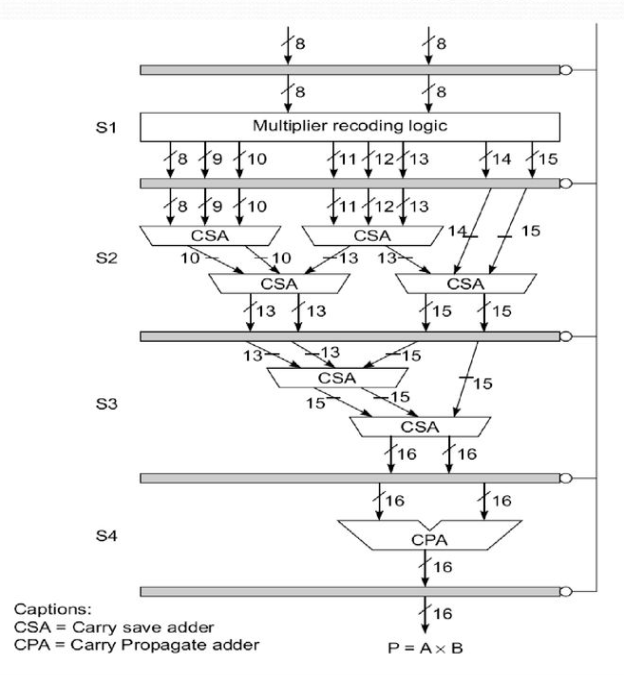
Fig 15: A pipeline unit for fixed point multiplication
● The first stage (S1) simultaneously generates all eight partial products, ranging from 8 to 15 bits.
● The second stage (S2) consists of two layers of four CSAs that combine eight numbers into four numbers ranging from 12 to 15 bits.
● The third stage (S3) is made up of two CSAs that combine four numbers from the first stage into two l6-bit numbers.
● The fourth and last step (S4) is a CPA, which adds the last two integers to produce the final result P.
Multifunctional Arithmetic Pipelines
● Uni-functional arithmetic pipelines are static arithmetic pipelines that are meant to fulfill a single function.
● The term "multifunctional" refers to a pipeline that may fulfill multiple functions.
○ A static or dynamic multipurpose pipeline is possible.
○ While static pipelines conduct one function at a time, dynamic pipelines can perform many functions at different times.
○ As long as there are no conflicts in the shared utilization of pipeline stages, a dynamic pipeline permits numerous functions to be performed simultaneously through the pipeline.
Q8) Explain super scalar and super pipeline design?
A8) In uniprocessors, instruction level parallelism is achieved mostly through pipelining and keeping many functional units busy executing numerous instructions at the same time. When a pipeline is longer than the standard five or six steps (e.g., I-Fetch, Decode/Dispatch, Execute, D-fetch, Writeback), it is referred to as Superpipelined. Superscalar refers to a processor that can execute several instructions at once. A superscalar architecture allows multiple instructions to be started at the same time and executed independently. A Superscalar pipeline architecture can be created by combining these two strategies.
Pipeline Design Parameters - For the pipeline processors to be investigated below, certain parameters used in constructing the scalar base processor and superscalar processor are given in the Table. All pipelines are considered to have k stages in them. The base cycle, or pipeline cycle, for the scalar base processor is considered to be l time units. The instruction issue rate, issue delay, and basic operation latency were all described. The greatest number of instructions that can be executed in the pipeline at the same time is known as instruction level parallelism.
All of these settings have a value of 1 for the base processor. The base processor is the basis for all processor types. The ILP is needed to fully utilize a given pipeline processor
Machine type | Scalar base machine of k pipeline stages | Superscalar machine of degree m |
Machine pipeline cycle | 1(base cycle) | 1 |
Instruction issue rate | 1 | m |
Instruction issue latency | 1 | 1 |
Simple operation latency | 1 | 1 |
ILP to fully utilize the pipeline | 1 | m |
Table: Design processor for pipeline processor
Super-pipeline
The concept of super-pipelining is to divide a pipeline's stages into substages, hence increasing the number of instructions supported by the pipeline at any given time. If we divide each stage in half, the clock cycle period t will be cut in half, t/2, and the pipeline will generate a result every t/2 s at maximum capacity. There is an optimal number of pipeline stages for a given architecture and instruction set; increasing the number of stages beyond this limit affects overall performance.
The superscalar architecture is one way to boost speed even more. By commencing operations at intervals of T/n, it may be able to execute at a faster rate given a pipeline stage time T. This can be done in one of two ways:
● Subdivide each stage of the pipeline into n substages.
● Provide a total of n overlapping pipelines.
The first method necessitates speedier logic and the ability to separate the phases into segments with consistent latency. More complicated inter-stage interlocking and stall restart logic may be required.
The second technique is similar to a staggered superscalar operation in that it has all of the same requirements as the first, with the exception that instructions and data can be obtained with a minor temporal offset.
Furthermore, because of the sub-clock period discrepancies in timing across the pipes, inter-pipeline interlocking is more complex to handle. Even so, superscalar designs may require staggered clock pipelines in the future to reduce peak power and the resulting power-supply induced noise. Alternatively, designs could be compelled to operate in a balanced mode, in which logic transitions are balanced by reverse transitions — a technique utilized in Cray supercomputers that resulted in the computer providing a pure DC load to the power supply and considerably reduced noise in the system.
The speed of reasoning and the frequency of unanticipated branches will inevitably restrict super pipelining. Stage duration can't go any shorter than the interstage latch time, therefore there's a limit to how many stages you can have.
Super scalar
The Cray-designed CDC supercomputers, in which many functional units are kept occupied by multiple instructions, gave rise to superscalar computing. The CDC machines could cram up to four instructions into a single word, which were then fetched and delivered via a pipeline. This arrangement was fast enough to keep the functional units active without surpassing the instruction memory, given the technology of the time.
The ability to give instructions in parallel has been enabled by current technology, but it has also generated the need to do so. Parallel execution has been required to boost performance as execution pipelines have neared their speed limits.
Because this necessitates higher memory fetch speeds, which haven't kept pace, it's become necessary to fetch instructions in parallel - fetching serially and pipelining their dispatch can no longer keep multiple functional units occupied. Simultaneously, the placement of the L1 instruction cache on the chip has allowed designers to fetch a cache line in parallel at a low cost.
Superscalar machines still use a single fetch-decode dispatch pipe to drive all of the units in some circumstances. After the third stage of a unified pipeline, the UltraSPARC, for example, splits execution. However, numerous fetch-decode dispatch pipes supplying the functional unit are becoming increasingly typical.
Superscalar pipeline structure/design
The instruction decoding and execution resources in an m-issue superscalar processor are augmented to essentially construct m pipelines running at the same time. Multiple pipelines may share functional units at particular pipeline stages.
A design sample of this resource-shared multiple pipeline topology is shown in Fig.a. If there are no resource conflicts or data dependencies, the processor can issue two instructions each cycle with this design. In the design, there are essentially two pipelines. Fetch, decode, execute, and store are the four phases of processing in both pipelines.
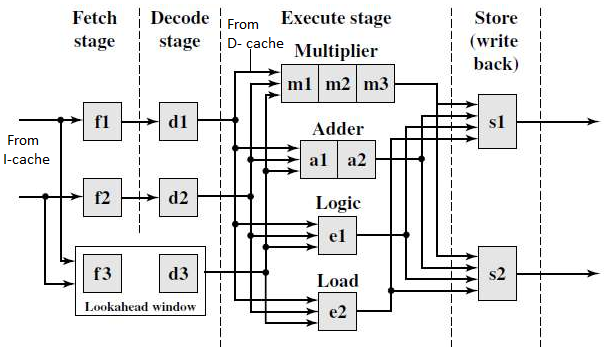

Fig 16: a - dual pipeline, super scalar processor, b - sample program and its dependence graph
Each pipeline, in essence, has its own fetch, decode, and store units. A single source stream feeds the two instruction streams that flow via the two pipelines (the I-cache). Resource restrictions and a data dependency relationship between successive instructions affect the fan-out from a single instruction stream.
Except for the execute stage, which may need a variable number of cycles, we assume that each pipeline stage requires one cycle for simplicity. In the execute step, four functional units are available: multiplier, adder, logic unit, and load unit. These functional units are dynamically shared between the two streams.
There are three pipeline stages in the multiplier, two in the adder, and one in each of the others.
The two store units (S1 and S2) can be employed dynamically by the two pipelines based on availability at any given cycle. A lookahead window exists, complete with its own fetch and decoding mechanism. In order to improve pipeline performance, the lookahead window is utilized for instruction lookahead in cases where out-of-order instruction issues are required.
Multiple pipelines must be scheduled at the same time, which necessitates complicated reasoning, especially when the instructions are acquired from the same source. The goal is to avoid pipeline stopping and keep pipeline idle time to a minimum.
Data dependence - A dependency graph is created in fig B to show the relationship between the instructions. We have flow dependence I1->I2 because the register content in R1 is loaded by I1 and subsequently used by I2.
Because the result in register R4 after executing 14 may affect the operand register R4 used by I2, we have anti-dependence: 13  14. Since 15 and 16 modify the register R6, and R6 supplies an operand for 16. We have both flow and output dependence: 15
  16 and 15
  16 as shown in the dependence graph.
These data dependencies must not be broken in order to schedule instructions through one or more pipelines (Eg fig ). Otherwise, incorrect results may be obtained.
Q9) Write the difference between an asynchronous and synchronous model?
A9) Difference between asynchronous and synchronous model
Asynchronous Model | Synchronous Model |
Data flow between adjacent stages is controlled by handshaking protocol. | Clocked latches are used to interface between stages. |
Different amount of delay may be experienced in different stages. | Approximately equal amount of delay is experienced in all stages. |
Ready and Acknowledgement signals are used for communication purpose. | No such signals are used for communication purpose. |
Transfer of data to various stages in not simultaneous. | All Latches Transfer of data to next stage simultaneous. |
No Concept of Combinational Circuit is used in pipeline stages. | Pipeline stages are combinational logic circuits. |
Q10) Write the difference between a fixed point and floating point?
A10) Difference between a fixed point and floating point
Fixed Point | Floating Point |
Limited Dynamic range | Large Dynamic Range |
Overview flow and quantization errors must be resolved | Easier to program since no scaling is required. |
Long product development time. | Quick time to market. |
Cheaper | More expensive |
Lower power consumption | High power consumption |