Unit – 1
Introduction
Q1) Define Distributed System. Explain goals/properties of distributed System. 8M
Ans.
Definition
Distributed System is a collection of multiple computers which are linked by the network to produce an integrated computing facilities. Distributed System is consider as LAN, MAN, or WAN in computer networks.
“A distributed system is a collection of independent computers that appears to its users as a single coherent system.”
The Distributed System changes its size depending upon the number of computers used in the network. Network consist of multiple computers are connected through the wired or wireless connection.
Following figure shows the Distributed system is work as a middleware in computer organization.
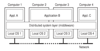
Fig (a)-A Distributed System work as middleware.
Above figure shows the Distributed System contains the three applications A, B and C. In this application B is distributed to other application and shares the interface.
Goals of Distributed System
Fowling are the key goals of Distributed System.
1) Resources Accessibility
Resource Accessibility is the key goal of distributed system in we can access the remote resources between the multiple users and applications. The resources such as computer, printer, storage devices, data, files, and web pages.
The main reason for resource sharing is economics. For example instead of buying and maintain a separate printer for each user in small office it is cheaper to share the printer among users.
Resource sharing is achieved by exchanging the information over the internet by using simple protocols such as http, ftp etc. for exchanging the files, mail, Documents, audio and video.
2) Transparency
Transparency makes the hiding of process details which are distributed on multiple computers.
It is used to achieving the image of a single system image without hiding the details of location, access, migration, concurrency, failure, relocation, persistence and resources to the users.
Types of Transparency
The concept of transparency can be applied to several aspects of a distributed system, following fig shows different types of transparency.
1. Access Transparency
Access Transparency hides the differences in data representation and the way that how resources can be accessed by users. In this type first we need to find how data is represented on different machine and operating system to hide differences in architecture.
For example in distributed system there are multiple computers with multiple operating system and multiple files are stored in it. Through the access transparency files can be hidden from the users.
2. Location Transparency
Location Transparency hide the resources where they located on computer system. Naming mechanism is used to achieve the location transparency.
In this type only logical names are assigned to resources. URL (Uniform resource locator) is used to assign the logical name. For example consider the URL https://www.shreeclass.com/index.html. Using this logical name we can access the index.html page but cannot find the physical location of it on server.
3. Migration Transparency
Migration Transparency hides the resources that moves from one location to another.
4. Relocation Transparency
Relocation Transparency hide a resource may be moved to another location while they are in use.
For example when users use the wireless network the can move at any location without affecting on the network.
5. Replication Transparency
It hides the resources is replicated.
6. Concurrency Transparency
Concurrency means different users at the same time access the same resource or system. When two or more different users save their files on the same file server or use the same resources. It hides the information about resources hide between different users.
7. Failure Transparency
Failure Transparency hides failure and recovery of resources.
3) Openness
Another important goal of distributed systems is openness. Open operating system provides the different services with standard rules and syntax.
For example, in computer networks, standard rules provide the format, contents, and meaning of messages sent and received. Such rules are made up within protocols. In distributed systems, services are generally specified through interfaces, which are described in an Interface Definition Language (IDL).
It Make the network easier to configure and modify component structure.
4) Reliability
Compared with single system, a distributed system should be highly capable of being secure, consistent and have a high capability of masking errors.
5) Performance
Distributed system provides the high performance for sharing the resources.
6) Scalability
Considering old communication system scalability is the most important goal for distributed system. It can be measured along at least three different dimensions that is geography, administration or size.
1) Size
The system can be scalable with respect to size that means we can easily add more number of users and resources to the system.
2) Geography
In this scalable system the users and resources may resides far apart.
3) Administration
Due to administration systems are easy to manage even it spans many independent administrative organization.
Q 2. Explain layered architecture and object based architecture in distributed system. 8M
Ans:
Architectural styles
In distributed system different architectural styles are present for successful development of large systems. The styles are important in terms of components, the way that components are connected to each other, the data exchanged between components and how these elements are jointly configured into a system.
Following are the most important architecture for distributed system.
1. Layered Architectures
2. Object-based Architecture
3. Data-centered Architecture
4. Event based Architecture
1. Layered Architecture
It is simple layered style in which components are organized in a layered fashion. Components of L1 layer is allowed to call components of L2 but no other way.
Consider the following figure it has n number of layers.
This model has been adopted by the networking community. In this architecture control generally follows from layer to layer. The request is go down and result is flow upward.
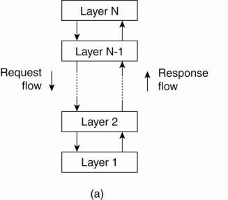
Fig .1.5(a) Layered architecture
2. Object based Architecture
Some organization follow the object based architecture. In this architecture objects are corresponds with what we defined as component. These components are connected through a remote procedure call mechanism.
The layered architecture and object based architectures is the most important styles for large software systems.
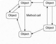
Fig 1.5(b) Object based architecture
Q 3. Explain distributed system architecture. 8M
System Architectures
System architecture is depends on where software components are placed. Selecting on software components, their interaction, and their placement leads 10 an instance of a software architecture, also called a system architecture.
1. Centralized Architecture
In the basic client-server model, processes in an exceedingly distributed system are divided into two parts. A server could be a process implementing a selected service, for instance, a file system service or a database service. A client may be a process that requests a service from a server by sending it a request and subsequently waiting for the server's reply. This client-server interaction, also called as request-reply behavior is shown in Fig.

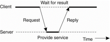
Fig. 1.5(e) General interaction between client and server
Communication between a client and a server can be implemented by using simple connectionless protocol such as UDP. In these cases, when a client requests a service, it simply packages a message for the server, identifying the service it wants, together with the required input file.
The message is then sent to the server. The latter, in turn, will always waiting for an incoming request, then process it, and package the results in a reply message that is then sent to the client.
Using a connectionless protocol has the plain advantage of being efficient. As long as messages don’t get lost or corrupted, the request/reply protocol just sketched works fine.
As another, many client-server systems use a reliable connection-oriented protocol. Although this solution isn’t entirely appropriate in a very local-area network because of relatively low performance, it works perfectly in wide-area systems during which communication is inherently unreliable.
Application layering
The client server model has multiple issues one in every of these is way to draw clear distinction between client and server. Considering that several client-server applications are targeted toward supporting user access to databases, many people have advocated a distinction between the subsequent three levels.
- User interface level
- Processing level
- Date level
The user-interface level contains all that’s necessary to directly interface with the user, such as display management. The processing level typically contains the applications.
The data level manages the particular data that’s being acted on. Clients typically implement the user-interface level. This level consists of the programs that allow end users to interact with applications. There is a substantial difference in how sophisticated user-interface programs are.
The simplest user-interface program is nothing quite a character-based screen. Such an interface has been typically utilized in mainframe environments.
For example, consider an Internet search engine. Ignoring all the animated banners, images on the internet user interface of a search engine is very simple in view. In this a user types a string of keywords and the data related to that string is appear on the screen as a list of titles on the web pages.
The back end is made by a huge database of Web pages. This web pages have been pre-fetched and indexed. The core of the search engine is a program that transforms the user's string of keywords which maps the one or more database queries.
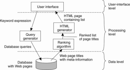
Fig 1.5(f) the simple organization of an internet search engine into three layers.
Multitiered Architecture
To implement client-server architecture require more number of computers. The simplest organization have two types of machines:
- A client machine containing only the programs implementing the user-interface level.
- A server machine containing the rest, that is the programs implementing the processing and data level
In this architectural organization everything is managed by the server. The client is work as dumb terminal. It provides the approach for organizing the clients and servers is to distribute the programs in the application layers.
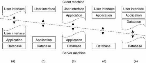
Fig 1.5(g) shows the Alternative Client-Server architecture a-e
Figure (a) shows the terminal dependent part of the user interface on the client machine and give the applications remote control over the presentation of their data.
Figure (b) shows the user-interface software on the client side. In such cases, we divide the application into a graphical front end, which communicates with the rest of the application which is on server through an application-specific protocol.
In this model the front end consider as a client software only present the application interface.
Figure(c) shows the application to the front end. The front end can then check the correctness and consistency of the form and represents where the user interaction required.
It shows the organization of a word processor in which the basic editing functions execute on the client side where they operate on locally cached, or in-memory data.
Figure (d) and (e) shows the organizations are used where the client machine is a PC or workstation, connected through a network to a distributed file system or database.
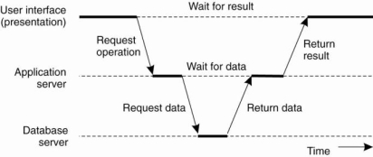
Figure 1.5(h) an example of server acting as client.
Above figure shows the three-tiered architecture n this programs that form part of the processing level reside on a separate server, but may additionally be partly distributed across the client and server machines. A typical example of where a three-tiered architecture is used is in transaction processing.
2. Decentralized Architecture
Multitiered client-server architectures are a direct consequence of dividing applications into a user-interface, processing components, and a data level.
In many business environments, distributed processing is appreciate organizing a client-server application as a multitiered architecture. We seek advice from this kind of distribution as vertical distribution. The characteristic feature of vertical distribution is that it’s achieved by placing logically different components on different machines.
A vertical distribution can help: functions are logically and physically split across multiple machines, where each machine is ready-made to a selected group of functions. Vertical distribution is only one technique of organizing client-server applications.
In modem architectures, it’s often the distribution of the clients and also the servers that counts, which we check with as horizontal distribution. During this form of distribution, a client or server may be physically divide into logically equivalent parts, but each part is working on its own share of the entire data set, thus balancing the load.
A. Structured peer-to-peer Architecture
Modern system architectures that support horizontal distribution, refer to as peer-to-peer systems. In a structured peer-to-peer architecture, the overlay network is constructed using a deterministic procedure. The procedures are used to organize the process through Distributed Hash Table (DHT).
In a DHT -based system, data items are assigned a random key from an outsized identifier space, like a 128-bit or 160-bit identifier. Likewise, nodes within the system are also assigned a random number from the same identifier space.
For example, in the Chord system (Stoica et al., 2003) the nodes are logically organized in a ring to that data item with key k is mapped to the node with the smallest identifier id ~ k. This node is observed because the successor of key k and denoted as succ(k), as shown in Fig. 1.5(i).
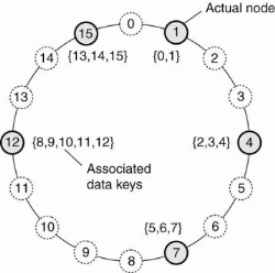
Figure 1.5(i) mapping of data items onto nodes in chord.
In this when a node wants to hitch the system, it starts with generating a random identifier id. Note that if the identifier space is large enough, then provided the random number generator is of excellent quality, the probability of generating an identifier that is already assigned to an actual node is near zero. Then, the node can simply do a lookup on id, which can return the network address of succiid).
At that time, the joining node can simply contact succiid) and its predecessor and insert itself within the ring. Of course, this scheme requires that every node also stores information on its predecessor. Insertion also yields that every data item whose key is now associated with node id, is transferred from succiid).
B. Unstructured peer-to-peer Architecture
Unstructured peer-to-peer systems largely depends upon randomized algorithms for constructing an overlay network. The most idea is that every node maintains a list of neighbors, but that this list is built in a more or less random way.
One of the goals of the many unstructured peer-to-peer systems is to construct an overlay network that resembles a random graph. The essential model is that every node maintains a listing of c neighbors, where, ideally, each of these neighbors represents a randomly chosen live node from this current set of nodes. The list of neighbors is referred to as a partial view.
C. Topology Management of Overlay Networks
One key observation is that by carefully exchanging and selecting entries from partial views, it’s possible to construct and maintain specific topologies of overlay networks. This topology management is achieved by adopting a two layered approach, as shown in Fig.
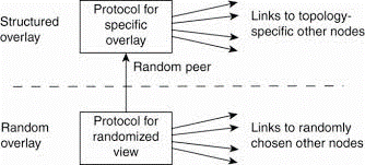
Fig 1.5(j) a two-layered approach for constructing and maintaining specific overlay topologies using techniques from unstructured peer-to-peer systems.
The lowest layer constitutes an unstructured peer-to-peer system within which nodes periodically exchange entries of their partial views with the aim to maintain the accurate random graph.
The lowest layer passes its partial view to the upper layer, where a further selection of entries takes place. This then result in second list of neighbors corresponding to the specified topology.
D. Super-peers
Nodes like those maintaining an index or acting as a broker are generally named as super-peers. As their name suggests, super-peers are often also organized in a very peer-to-peer network, resulting in a hierarchical organization as explained in Yang and Garcia-Molina.
A simple example of such an organization is shown in Fig. 1.20. During this organization, every regular peer is connected as a client to a super-peer. All communication from and to a daily peer proceeds through that peer's associated super-peer.
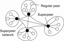
Fig 1.5(k) A hierarchical organization of nodes into a super-peer network.
In many cases, the client-super-peer relation is fixed. When a regular peer joins the network, it attaches to one of the super-peers and remains attached until it leaves the network. Obviously, it is expected that super-peers are long-lived processes with a high availability.
To make amends for potential unstable behavior of a super-peer, backup schemes can be deployed, such as pairing every super-peer with another one and requiring clients to attach to both.
Q 4. Explain Event based and data centered Architecture in detail. 8M
Architectural styles
In distributed system different architectural styles are present for successful development of large systems. The styles are important in terms of components, the way that components are connected to each other, the data exchanged between components and how these elements are jointly configured into a system.
Following are the most important architecture for distributed system.
1. Layered Architectures
2. Object-based Architecture
3. Data-centered Architecture
4. Event based Architecture
3. Data-centered Architecture
In the data centered architecture process communication takes place through common passive or active repository. In distributed system Data centered architecture is more important same as the layered and object based architectures.
Consider the example wealth of networked applications which are developed through
Shared distributed file system. In this application communication takes place through the files.
4. Event based Architecture
In event-based architectures, processes essentially communicate through the propagation of events, which optionally also carry data, as shown in Fig. 1.11.
Event propagation in distributed system is known as publish/subscribe system. The basic idea for implementing the Event based architecture is that processes publish events after which the middleware ensures that only those processes that subscribed for only those events will receive them.
The advantage of event-based systems is that processes are loosely coupled that means they need not explicitly refer to each other. This is also referred to as being decoupled in space.
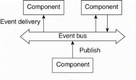
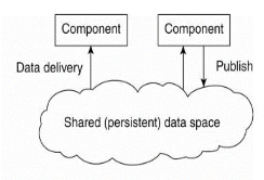
Fig 1.5(c)(d) shows Event based and shared data-space architecture.
Event-based architectures can be combined with data-centered architectures, which is additionally referred to as shared data spaces. The essence of shared data spaces is that processes are now also decoupled in time: they have not both move when communication takes place.
Q 5. Explain Hybrid Architectures in Distributed system. 8M
Hybrid Architectures
Hybrid Architecture is combine some specific classes of distributed systems during which client-server solutions are combined with decentralized architectures.
1. Edge-Server Systems
An important class of distributed systems that’s organized in line with a hybrid architecture is made by edge-server systems. These systems are deployed on the web where servers are placed "at the edge" of the network.
This edge is credited by the boundary between enterprise networks and there for the actual Internet, for instance, as provided by an Internet Service Provider (ISP).
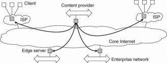
Fig 1.5(l) Viewing the Internet contains of a collection of edge servers.
End users refer as a client connect to the Internet by means of an edge server. The edge server's main purpose is to serve content, possibly after applying filtering and transcoding functions.
2. Collaborative Distributed Systems
Hybrid structures are notably deployed in collaborative distributed systems. The most issue in many of those systems to first start, that often a standard client-server scheme is deployed. Once a node has joined the system, it can use a completely decentralized scheme for collaboration.
Consider the example of BitTorrent file sharing system. BitTorrent could be a peer-to-peer file downloading system. Its principal working is shown in Fig. 1.22.
The fundamental idea is that when an end user is trying to find a file, he downloads chunks of the file from other users until the downloaded chunks will be assembled together yielding the complete file. An important design goal was to ensure collaboration.
To download a file, a user needs to access a global directory, which is just one of a few well-known Web sites. Such a directory contains references to what are called .torrent files. A .torrent file contains the information that is needed to download a specific file.
In particular, it refers to what’s referred to as a tracker, which is a server that is keeping an accurate account of active nodes that have (chunks) of the requested file.

Fig 1.5(m) the principal working of BitTorrent [adapted with permission from Pouwelse et al. (2004)].
Once the nodes are identified from where chunks are often downloaded, the downloading node effectively becomes active.
Q 6. Explain role of TP monitor in distributed system 8M
The operation on database are performed in the form of transaction. The transactions are performed using programming languages. To perform the transaction distributive system provides the special primitives. The list of primitives depends on what kind of objects are being used in the transaction.
Following are the primitives used in transaction processing system.
- BEGIN_TRANSACTION: It starts the transaction
- END_TRANSACTION: It ends the transaction and try to commit
- ABORT_TRANSACTION: Kills the transaction and restore the old value
- READ: Read the data or files
- WRITE: Write the data to file or table
In a mail system, there might be primitives to send, receive, and forward mail. In an accounting system primitive might be READ and WRITE. Ordinary statements, procedure calls are also allowed inside a transaction. Remote procedure calls (RPCs) is procedure calls to remote servers are also used in a transaction which is known as a transactional RPC.
In enterprise middleware systems, the component handled by distributed transactions formed the core for integrating applications at the server or database level. This component is known a transaction processing monitor or TP monitor. Its main task was to allow an application to access multiple server/databases by offering it a transactional programming model, as shown in Fig. 1.7(c).
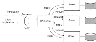
Fig 1.3(d) shows a role of TP monitor
Q 7. Discuss scalability limitations in distributed system. 8M
Scalability Limitations
When a system required to scale, multiple types of problems are occurs. The first problem related to scaling with respect to size. If more users or resources required to be supported, we are confronted with the limitations of centralized services, data, and algorithms. For example, many services are centralized with respect to that they are implemented by using only a single server running on a particular machine in the distributed system.
The problem with this scheme is obvious that the server can become a bottleneck when the number of users and applications are increases. Even if we have virtually unlimited processing and storage capacity, communication with that server will restricted for further growth.
Unfortunately using only a single server is sometimes unavoidable. Consider that we have a service for managing highly confidential information like medical records, bank accounts, and many more. In this cases, it may be best to implement that service by means of a single server in a highly secured separate room, and protected from other parts of the distributed system through special network components.
Copying the server to several locations to increase performance maybe out of the question as it would make the service not more secure.
Concept | Example |
Centralized services | A single user for all users |
Centralized data | A single on line telephone link |
Centralized Algorithm | Performing routing based on complete information |
Figure shows Examples of scalability limitations.
Just as bad centralized services are centralized data. Question arise that how should we keep track of the telephone numbers and addresses of 50 million people? Suppose that each data record fit into 50 characters. A single 2.5-gigabyte disk partition would provide enough storage. But here again, having a single database would undoubtedly saturate all the communication lines into and out of it. Same as imagine how the Internet would work if its Domain Name System (DNS) was still implemented as a single table.
DNS maintains information on millions of computers worldwide and forms a required service for locating Web servers. If each request to resolve a URL had to be forwarded to that one and only DNS server then no one would be using the Web.
The centralized algorithms are also a not good idea. In a large distributed system, an enormous number of messages have to be routed over many lines. From a theoretical point of view, the optimal way to do this is collect complete information about the load on all machines and lines, and then run an algorithm to compute all the optimal routes. This information can then be spread around the system to improve the routing.
Q 8. Explain types of transparencies in distributed systems. 8 M
Transparency
Transparency makes the hiding of process details which are distributed on multiple computers.
It is used to achieving the image of a single system image without hiding the details of location, access, migration, concurrency, failure, relocation, persistence and resources to the users.
Types of Transparency
The concept of transparency can be applied to several aspects of a distributed system, following fig shows different types of transparency.
1. Access Transparency
Access Transparency hides the differences in data representation and the way that how resources can be accessed by users. In this type first we need to find how data is represented on different machine and operating system to hide differences in architecture.
For example in distributed system there are multiple computers with multiple operating system and multiple files are stored in it. Through the access transparency files can be hidden from the users.
2. Location Transparency
Location Transparency hide the resources where they located on computer system. Naming mechanism is used to achieve the location transparency.
In this type only logical names are assigned to resources. URL (Uniform resource locator) is used to assign the logical name. For example consider the URL https://www.shreeclass.com/index.html. Using this logical name we can access the index.html page but cannot find the physical location of it on server.
3. Migration Transparency
Migration Transparency hides the resources that moves from one location to another.
4. Relocation Transparency
Relocation Transparency hide a resource may be moved to another location while they are in use.
For example when users use the wireless network the can move at any location without affecting on the network.
5. Replication Transparency
It hides the resources is replicated.
6. Concurrency Transparency
Concurrency means different users at the same time access the same resource or system. When two or more different users save their files on the same file server or use the same resources. It hides the information about resources hide between different users.
7. Failure Transparency
Failure Transparency hides failure and recovery of resources.