Unit - 1
Basics of Control System
Q1) Find SFG for the block diagram below?
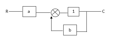
Fig 1 Block Diagram
A1)
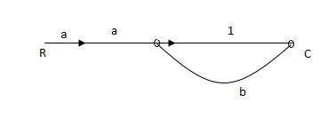
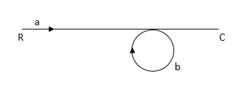
Fig 2: Required SFG
Ra+cb =c
c/R= a/1-b
Q2) The SFG shown has forward path and singles isolated loop determine overall transmittance relating X3 and X1?
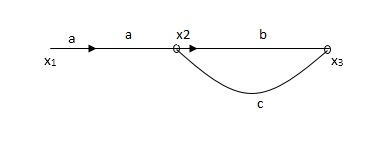
Fig 3 SFG
A2)
X1- I/p node
X2-Intenmediale node
X3- o/p node
Ab- forward path (p)
Bc- 1 loop (L)
At node XQ:
X2 = x1a + x3c [Add i/p signals at node]
At node x3:
x2b =x3
(x1a+x3c) b = x3
X1ab = x3 (1-bc)
X1 = x3 (1-bc)/ab
Ab/(1-bc) = x3/x1
T= p/1-L
Q3) Find the Transfer function for the SFG given below?

Fig 4 SFG
A3)
X1:- I/p node x2, x3,x4,x5,Qnlexmedili node
X0:- o/p node abdeg:- forward path
Bc, ef :- Loop [isolated]
x2 = ax1+c x3
x3= bx2
x4 = d x3+f x5
x5 = e x4
x6= g x5
x6 = g(e x4) = ge [dx3+ e f x5]
xb = ge [d (bx2) + f (e x4)]
xb = ge [ db (ax1+cx3) + fe (dx3+ fx5)]
xb = ge [db (ax1+cb (ax1+x3) +fe[cdbx2]+
f( e [db (ax1+ cx3)
x2 = ax1 + cb (x2) x4 = d bx2 + f exq
x2 = ax1 + cbx2 = db (d4) + fe/1-cb
x2 = ax1/(1-cb) xy = db x2 + f x6/g
xy = db [ax1]/1-cb + f xb/g
x5 = c db ( ax1)/1-cb + efxb/g
xb = gx5
= gedb (ax1)/1-cb + g efxb/g
Xb = gx5
Gedb (ax1)/1-cb + g efxb/g
(1- gef/g) xb = gedb ax1/1-ab
Xb/x1 = gedb a/ (1- ef – bc + beef
Xb/x1 = p/ 1- (L1+L2) + L1 L2 for isolated loops
Q4) Reduce given B.D to canonical (simple form) and hence obtain the equivalent Tf = c(s)/ R(S)?
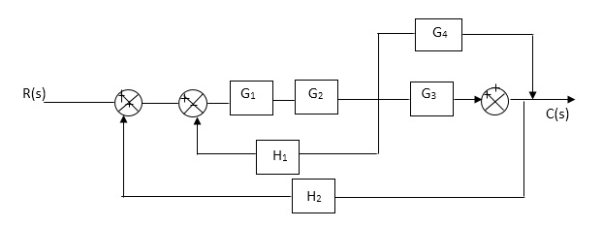
Fig 5 Block Diagram


 A4)
A4)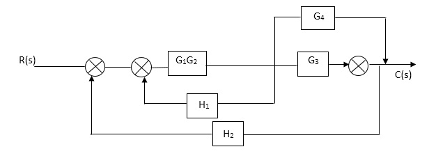


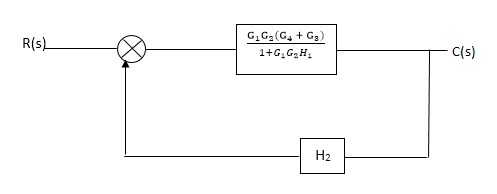
Fig 6 Reduced Block Diagram
C(S)/R(S) = (G1G2) (G3+G4)/1+G1G2H1)/1-G1,G2(G3+G4) H2/1+G1G2H1
= G1G2(G3+G4)/1+G1G2H1-G1G2H2(G3+G4)
=G1G2(G3+G4)/1+(H1-H2)(G1G2) (G3+G4)
C(s)/R(S) = G1G2(G3+G4)/1+(H1-H2(G3+G4)) G1 G2
Q5) Reduce the Block diagram
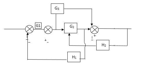
Fig 7 Block Diagram
A5)
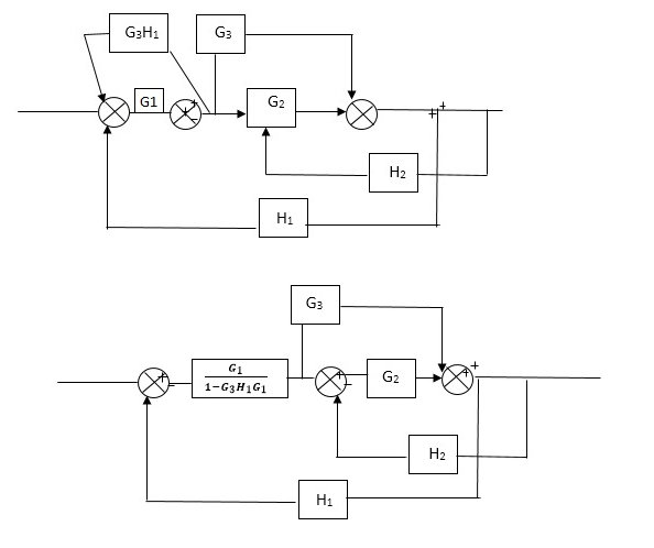
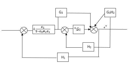
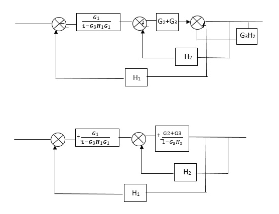
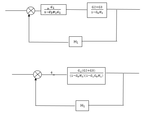
Fig 8 Final Reduced Block Diagram
C(s)/R(s)= G1(G3+G2)/(1-G1G3X1) (1-G2X2) H1
= G(G3+G2)/(1-G3G1H1) (1-G2H2) + G1H1(G3+G2)
= G1(G3+G2)/1-63G1H1-G2H2+G1H1(G3+G2H1
=G1(G3+G2)/1-G3H2+G1G2H1(1+G3H2)
Q6) Reduce using Masons gain formula
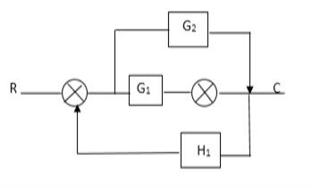
Fig 9 Block Diagram
A6)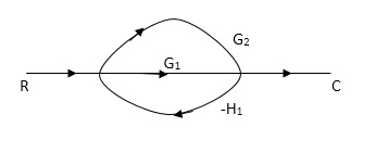
Fig 10 SFG for Fig 8
P1= G1 p2 =G2 Delta1 =1
L1= -G1 H1
 = 1-(-G1H1)
= 1+G1H1
T= G1+G2/1+G1H1
Q7) Determine overall gain reliably x5 and x1 Draw SFG
X2 = ax1+ f x2
X3= bx2 +exy
X4 = cx3+hx5
X5 =dx4 + gx2
A7)
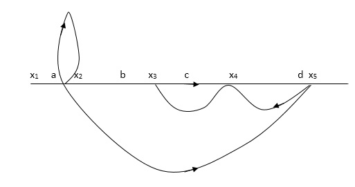
Fig 11 SFG
P1 = abcd p2 = ag
L1 = f L2 = ce, L3= dh
 1 = 1
1 = 1
 2= 1-ce
 = 1-[L2+L2+L3] + [L1 L2 +L1 L3]
= 1-[f+ le = dh] + [fce +fdh]
T= abcd+ ag (1-ce)/1-[ftce + dh ] + (fce + fdh)
Q8) For the given electrical system below draw the analogous system find V0(s)/V1(s)
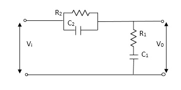
Fig 12 Electrical Circuit
A8)
Let Z1 = R2 11 1/c2
=R2*1/c2s/R2+1/c2s
Z1= R2/1+R2c2s
Let Z2 = R1+1/c1s
Z2= 1+R1c1s/c1s
V0(s)/vi(s) = z2/z1+z2
=1+R1c1s/c1s/R2/1+R2c2s+1+R1c1s/c1s
V0(s)/v0(s) =(c1+R1c1s) (1+R2c2s)/R2c1s+1+sR1c1s2R1R2c1c2
Q9) Difference between open and closed loop system?
A9)
Open Loop System | Closed Loop system |
1.It does Not have any feedback. | 1. This system comprise of feedback |
2.As no feedback so easier to build. | 2.As it has feedback so difficult to build |
3.Theaccuracy of this system depends on the calibration of input. | 3.They are accuracy because of the feedback. |
4.Open Loop system are more stable. | 4.In closed Loop system stability depends on system components. |
5.optimization is not possible | 5. Optimization is possible |
6.These system are not reliable. | They are more reliable |
Q10) Explain Mason’s gain formula?
A10)
T= 
The overall transmittance Coverall gain can be determined by Masks formula.
Explanation:
Pk forward path transmittance of k+n path from a specified i/p node to n o/p nods
While calculating ipnode to n o/p nods.
While calculating ip no node should be encountered (used) more than ones.
 it is the graphics determined which involves of transmittances and multiple increases b/w non touching loops.
 = 1- [sum of all individual loop transmitting]
+[ sum of loop transmittance product of all possible non- touching loops]
-[sum of loop transmittance of all possible triples of non- touching loops]
 path factor associated with concered path & involves all a in the graphic which are isolated from forward path under consideration.
The path factor  for kthis equal to graph determinant of SFG which effect after erasing the kth path from the graph
Q11) List advantages of block diagram reduction technique?
A11)
- Very simple to Construct the Block diagram of complicated electrical & mechanical sys.
- The function of individual element can be visualized form block diagram
- Individual as well as overall performance of the system can be studied by the if shown in Block diag.
- Overall CLTf can be easily calculated by Block diagram reduction rules.