Unit - 4
DESIGN OF ARITHMETIC BUILDING BLOCKS AND SUBSYSTEM
Q1) What is meant by bit-sliced data path organization and what are the advantages of data path operators?
A1) A data path is a collection of functional units, such as arithmetic logic units or multipliers that perform data processing operations, registers, and buses. Along with the control unit it composes the central processing unit (CPU).
Advantages: To implement the logic function using n-identical circuits Data may be arranged to flow in one direction, while any control signals are introduced in an orthogonal direction to the data flow.
Q2) List out the components of data path
A2) Register Adder Shifter Multiplexer
Q3) Give the applications of high-speed adders
A3) Addition is one of the essential operations in Digital Signal Processing (DSP) applications which include Fast Fourier Transform (FFT), Digital filters, multipliers etc. With the advancements in technology, research is still going on to design a adder that performs addition in flash of time. One of such high-speed adder is carry save adder (CSA).
Q4) Determine propagation delay of n-bit carry select adder
A4) tp = tsetup +M tcarry +(N/M) tmux + tsum
Q5) Why barrel shifter very useful in the designing of arithmetic circuits
A5) A common usage of a barrel shifter is in the hardware implementation of floating-point arithmetic. For a floating-point add or subtract operation, the significant of the two numbers must be aligned, which requires shifting the smaller number to the right, increasing its exponent, until it matches the exponent of the larger number. This is done by subtracting the exponents and using the barrel shifter to shift the smaller number to the right by the difference, in one cycle. If a simple shifter were used, shifting by n bit positions would require n clock cycles.
Q6) Write the principle of any one fast multiplier?
A6) The Wallace tree has three steps:
Multiply each bit of one of the arguments, by each bit of the other, yielding n2 results.
Reduce the number of partial products to two by layers of full and half adders.
Group the wires in two numbers, and add them with a conventional adder
Q7) Why we go to Booth’s algorithm?
A7) Booth algorithm is a method that will reduce the number of multiplicand multiples. For a given number of ranges to be represented, a higher representation radix leads to fewer digit.
Q8) Define accumulator.
A8) An accumulator is a register in which intermediate arithmetic and logic results are stored. Without a register like an accumulator, it would be necessary to write the result of each calculation (addition, multiplication, shift, etc.) To main memory, perhaps only to be read right back again for use in the next operation.
Q9) How CLA differ from RCA
A9)
S. No | CLA | RCA |
1 | The carry look ahead adder (CLA) solves the carry delay problem by calculating the carry signals in advance, based on the input signals. | In the ripple carry adder, the output is known after the carry generated by the previous stage is produced. |
2 | It is based on the fact that a carry signal will be generated in two cases: (1)when both bits ai and bi are 1, or (2) when one of the two bits is and the carry in is 1. | Thus, the sum of the most significant bit is only available after the carry signal has rippled through the adder from the least significant stage to the most significant stage. As a result, the final sum and carry bits will be valid after a considerable delay. |
Q10) Explain the concept of carry look ahead adder with neat diagram
A10) Carry Look ahead adder
To improve the speed of addition operation, carry propagation delay of adders is important.
- Carry look ahead adder reduces circuit delay in ripple carry adder by calculation carry generation Cg, carry propagation, Cp.
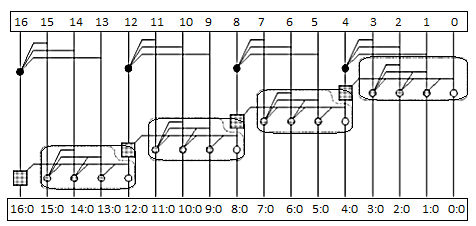
- Carry-look ahead adder computes Gi:0 for many bits in parallel.
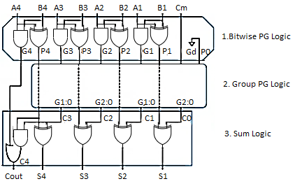
- Hence, addition can be reduced to a three-step process: - Computing bitwise generate and propagate signals using Gi=Ai.Bi, Pi=Ai Bi
- Combining PG signals to determine group generates Gi–1:0 for all N > i >1 using Gi=Ci+PiGi-1
- Calculating the sums using Si=Pi Gi–1:0
- Some of the hardware can be shared in the bitwise PG logic

Fig. Look ahead carry
- Uses higher-valency cells with more than two inputs

In general, a CLA using k groups of n bits each has a delay of tCLA = tpg +tpg(n)+[(n-1) + (k-1)] tAO + txor
