Unit - 6
Performance of Transmission Line
Q1) Classifcation of lines based on length and voltage levels such as short, medium and long lines.
A1)
Short Transmission Line
If the line is not more than 80 KV or if the voltage is not over than 66 KV then the line is known as the short transmission line. The capacitance of the line is governed by their length.
The effect of capacitance on the short transmission line is negligible, but for cable where the distance between the conductor is small, the effect of capacitance cannot be ignored.
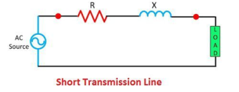
Figure. Short transmission line
Medium Transmission Line
The line which is ranging from 80 to 240 km is termed as a medium transmission line. The capacitance of the medium transmission line cannot be ignored. The capacitance of the medium transmission line is lumped at one or more point of the lines.
The effect of the line is more at high frequency, and their leakages inductance and capacitance considered to be neglected. The medium transmission line is sub-divided into Pi – model and T – model.
Long Transmission Line
The line having a length more than 240 km is considered a long transmission line. All the four parameters (resistance, inductance, capacitance, and leakage conductance) are found to be equally distributed along the entire length of the line.
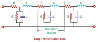
Figure. Long transmission line
Q2) Explain the Performance of short transmission lines with voltage relationship?
A2)
The equivalent circuit of a short transmission line is shown in Figure where R and X represent the total resistance and inductive reactance of both the conductors that is go and return of a single- phase transmission line.
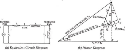
Figure. Short transmission line
Fig (a) represent a 3-phase short transmission line if R and X represent the resistance and inductive reactance to neutral, I is the current in one conductor, VR is the receiving-end voltage to neutral, VS is the sending-end voltage to neutral, and the load is that in one phase; the voltage drop found in this way is the drop between a phase and neutral.
The Receiving-end voltage, VR = VS – I (R + j X) = VS – IZ … (1)
The quantity I Z is the voltage drop along the line.
In Fig. (b) phasor OI, OA AB, BC, AC and OC represent the load current I, receiving-end voltage VR, resistive drop I R in line, reactive drop I X in line, line impedance drop I Z and sending-end voltage VS respectively.
From phasor diagram shown in Fig. (b),
Sending-end voltage Vs = OC = √ OF 2 + FC 2
= √ (OD + DF) 2 + (FB +BC) 2
= √ (VR cos ɸ R + IR) 2 + ( VR sin ɸR + IX) 2 -------(2)
Sending end phase angle ɸs = tan -1 FC/OF = VR sin ɸR + IX / VR cos ɸR + IR ----(3)
And sending end power factor cos ɸs = OF/OC = VR cos ɸR + IR/ Vs
Q3) Explain the nominal T method?
A3)
Nominal T Method
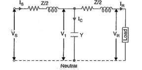
In Nominal T model of Transmission line, the whole shunt capacitance of line is assumed to be lumped at the middle of the line.
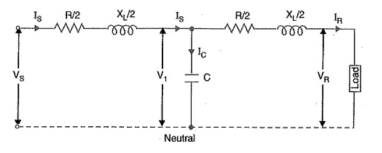
Let us now try to find the sending end voltage and current.
For that, we will apply kirchhof’s law.
Each parameter is shown in figure above with their meaning.
As the voltage across the shunt capacitance
V1 = (R/2 + jX/2)IR + VR ………(1)
Also, using Kirchhof’s current law,
Is = IR + Ic (phasor sum) ………………………….(2)
Therefore,
Vs = (R/2 + jX/2)Is + V1
= (R/2 + jX/2)IR + (R/2 + jX/2)Is + VR …………………….(3)
Let us now take the receiving end voltage as reference and assume that receiving end current or load current is lagging by some angle ØR.
Therefore,
VR = VR + j0
And IR = IR<-ØR = IR (CosØR – jSinØR)
As the current through the shunt capacitor lead by an angle 90° with respect to voltage across it i.e. V1, therefore
Ic = jωCV1
From equation (2),
Is = IR (CosØR – jSinØR) + jωCV1
= IR CosØR + j(ωCV1 – SinØR) ………………..(4)
Thus, by putting the value of V1 from equation (1) in equation (4), sending end current can be found.
Similarly, the sending end voltage can be calculated by putting the value of Is in equation (3). can also be calculated as we know the sending and receiving end voltage.
Q4) Explain nominal π method?
A4)
In Nominal π Method, the shunt capacitance of each line i.e. phase to neutral is divided into two equal parts. One part is lumped at the sending end while the other is lumped at receiving end as shown in figure below.
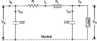
In this method there is no effect of shunt capacitance at sending end on the line voltage drop and hence on voltage regulation but this accounts for the charging current in sending end.
Let
IR = Load Current per phase
R = Resistance per phase
X = Reactance per phase
C = Capacitance per phase
CosØR = Receiving end power factor (lagging)
Vs = Sending end voltage
Q5) Explain Ferranti effect?
A5)
The Ferranti effect is a phenomenon that describes the increase in voltage that occurs at the receiving end of a long transmission line relative to the voltage at the sending end.
The Ferranti effect is more prevalent when the load is small, or no load is connected that is an open circuit. The Ferranti effect can be stated as a factor, or as percent increase.
Q6) Explain the representation of π and T of two port networks?
A6)
Representation of ‘T’ and ‘π’ models of lines as two port networks
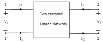
Figure: Two port network
Transmission parameters
A two-port network can be described by transmission parameters.
V1 = a11 V2 – a12 I2 ------------------------------------------(1)
I1 = a21 V2 – a22 I2 ------------------------------------------(2)
Where V2 and I 2 are independent variables and V1 and I1 are dependent variables. In matrix form, the above two equations can be rewritten as

The transmission parameters can be found as
a11 = V1/V2 | I2 =0
a12 = -V1/I2 | V2=0
a21 = I1/V2 | I2=0
a22 = -I1/I2 | V2=0
The transmission parameters express the primary (sending end) variables V1 and I1 in terms of the secondary (receiving end) variables V2 and - I 2 .
The negative of I 2 is used to allow the current to enter the load at the receiving end.
Π Model
A two-port network can also be represented using y-parameters.
The describing equations are
I1 = y11 V1 + y12 V2 -------------------------------------------------------(1)
I2 = y21 V1 + y22 V2 ---------------------------------------------------------(2)
Where
V1 and V2 are independent variables
I1 and I2 are dependent variables
y 11= I1/V1 | V2 =0
y12= I1/V2 | V1=0
y21 = I2/V1 |V2=0
y22 = I2/V2| V1=0
The y-parameters are also called short-circuit admittance parameters. They are obtained as a ratio of current and voltage and the parameters are found by short-circuiting port 2 (V2 = 0) or port 1 (V1 = 0).
Q7) Find the y-parameters of the pi (π) network shown in Figure
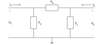
Figure. Pi network
A7)
Using KCL, we have
I1 = V1 Ya + (V1 -V2) Yb = V1(Ya +Yb) – V2 Yb
I2 = V2 Yc + (V2-V1) Yb = -V1 Yb + V2(Yb + Yc)

Q8) Explain the Determination of Generalised Constants for Transmission Lines for short lines?
A8)
The sending end voltage (VS) and sending end current (IS) of a transmission line can be expressed as:
 =
= 
 +
+ 
 ------------------------(i)
 =
=  +
+ 
 --------------------------(ii)
To determine the values of these constants for different types of transmission lines.
Short lines: In short transmission lines, the effect of line capacitance is neglected. Therefore, the line is considered to have series impedance. Shows the circuit of a 3-phase Circuit Constants of a Transmission Line on a single phase basis.
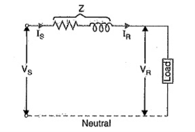
Figure. Short lines
 =
=  --------------------------(3)
 =
=  +
+ 
 -----------------------------(4)
Comparing these with eqs, (i) and (ii), we have,
 = 1;
= 1;  =
=  ,
,  =0 and
  =1
=1
Incidentally  =
= 

 -
-  ,
,  = 1 x 1 -
  x 0 =1
Q9) Explain the Determination of Generalised Constants for Transmission Lines for medium lines?
A9)
Medium lines — Nominal T method. In this method, the whole line to neutral capacitance is assumed to be concentrated at the middle point of the line and half the line resistance and reactance are lumped on either side as shown in Figure.
 =
=  +
+ 
 /2
/2
 =
=  +
+ 
 /2
/2
 =
=  -
-  =
= 
 Y = shunt admittance
=  (
(  +
+ 
 /2 )
/2 )
 =
=  +
+ 
 +
+ 

 /2
/2
= 
 +
+ 
 /2)
/2)
Substituting the value of V1 in we get,
 =
=  +
+ 
 /2 +
/2 + 
 /2
/2
Substituting the value of IS, we get,
 =
= 

 2 )
2 )  + (
+ (  +
+ 
 /4)
/4) 
Comparing eqs.
 =
=  = 1 +
= 1 + 
 /2 ;
/2 ;  =
=  (1+
(1+ 
 /4) ;
/4) ;  =
= 
Q10) Explain transmission efficiency?
A10)
Transmission efficiency is a parameter which displays how much percentage of input power at sending end is delivered to the receiving end.
Then % transmission efficiency η = PRx100 / Ps %
But Ps = VsIsCosØs
And PR = VRIRCosØR
Where CosØs = Sending end power factor
And CosØR = Receiving end power factor
Hence,
% Transmission Efficiency
η= [VRIRCosØR / VsIsCosØs]x100%
If Ps is the input power at sending end, then only (Ps – Loss) will be available at the receiving end. Therefore (100 -η)% is the loss in transmission line resistance. This gives us a new method to calculate transmission efficiency.
If we know the loss in the line, then efficiency can be calculated as
% Efficiency η = [(Input Power – Loss) / Input Power]x100 %
= [(Ps – Loss) / Ps]x100 %
= [Ps/Ps – Loss/Ps]x100 %
= [1 – Loss/Ps]x100 %
If the resistance of line is R and current flowing through it is I then ohmic loss = I2R
So,
% Efficiency η = [1- I2R/Ps]
= [1- I2R / VsIsCosØs]
= [1- IR / VsCosØs] ..(since Is = I = current in transmission line)