Unit - 3
Apparatus Protection
Q1) What is the nature of transformer faults & faults in auxiliary equipment?
A1) Nature of Transformer Faults
Power Transformers generally develop rare faults as it is static, totally enclosed and oil immersed but if these faults sustain the results may be serious unless the transformer is disconnected. The faults that generally occur in the transformer can be divided as:
1. Faults in auxiliary equipment which is a part of the transformer
2. Faults in the transformer winding and connections
3. Overloads and external short circuits.
Faults in Auxiliary Equipment
The detection of faults in auxiliary equipment is necessary to prevent ultimate failure of the main transformer windings. In these the components are
(i) Transformer oil: Oil is used as an insulator in transformer. So when low oil is present the live parts and the bushing leads gets exposed which are supposed to be beneath the oil. Oil level can be determined by the means of alarm indicators for immediate attention.
(ii) Gas cushion: The presence of oxygen or moisture may lead to deterioration of the transformer oil. Hence exclusion of this presence is necessary. Since the operating pressure varies within the tank, hence sealing of the tank is not an option. Pressure indicators and conservators are used to counter the expansion and contraction of oil. Whereas silica gel is provided in the breathing vent to absorb the moisture content. Sometimes a nitrogen cylinder is provided to provide an inert atmosphere maintaining the pressure between 0.5 and 0.8 atm.
(iii) Oil pumps and forced air fans: The top oil temperature normally gives the indication of the load on the transformer. A rise in temperature would indicate an overloading situation or due to the fault in cooling system. A thermometer with alarm contacts will indicate the temperature rise in oil due to any of these faults.
(iv) Core and winding insulations: These faults can turn into major faults if not taken care of. Insulation failures may develop if
(a) The insulation of the laminations and core bolts may be of poor quality. (b) Poor quality of insulation between windings or between winding and the core.
(c) Badly made joints or connections.
Winding Faults Electrical Faults that can cause immediate serious damage and are determined by the presence of unbalanced current or voltage may be divided into following classes:
(i) Faults between adjacent turns or parts of coils such as phase-to-phase faults on the HV and LV external terminals or on the winding itself or short circuits between turns of HV and LV windings.
(ii) (ii) Faults to ground or across complete windings such as phase-to-earth faults on either HV or LV side.
A short circuit between turns can start with a point contact resulting from mechanical forces or insulation deterioration due to excessive overload. The puncture of the turn insulation would cause a path through which the normal frequency voltage can maintain an arc. But if the voltage is insufficient to maintain the arc, it would be quenched by the oil present.
In the second case the ground faults are easy to detect as they are characterized by emission of large amount of gas due to decomposition of oil as well as in large values of fault currents. Rapid clearance is necessary to avoid excessive damage and to maintain stability.
Q2) What is the Differential Protection Scheme of Transformers?
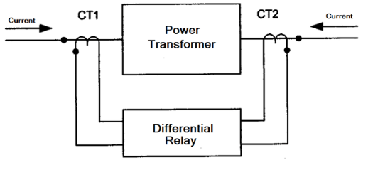
A2) The best way of protection of any apparatus against an internal fault is by the method of differential protection scheme since it covers the apparatus’ zone of protection. So for a transformer having ratings of 5 MVA and above, the differential scheme serves as an important protection against internal phase-to-phase and phase-to-earth faults. Any fault in the protected part would result in the deviation. Of the current intensities at the input and output. So the result of this unbalance current can be employed for the tripping of the relay. For this reason the differential scheme combines the characteristics of selectivity and highest tripping time of the relay. A particular differential scheme is given below for a three-phase star delta transformer.
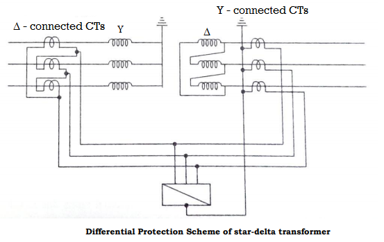
For the relay to detect 0 spill current in normal operation, the currents incoming from both the CTs should be in direct opposition. Since in a star delta transformer the line currents have a displacement of 30˚, so the CTs have to be connected in delta on the star side of the transformer and in star for the delta side to avoid any spill current through relay in normal operation. Another advantage of this connection is the avoiding of triplet harmonics to appear on the line currents due to delta windings.
Q3) Explain the Generator Protection with faults?
A3) The generator is the prime equipment in the power system. The increased size of the generators and even greater increase in their capacity makes the imperative to protect them against fault. Unlike other apparatus only isolating the circuit breaker is not enough to prevent further damage as the generator would still supply power to its stator windings until the excitation is suppressed. So for isolation it is needed to open the field to avoid any excitation, and to stop the fuel supply to the prime mover.
Generator faults
Generator faults can be considered as follows.
(a) Stator faults: These include the following (i) Phase to earth faults. (ii) Phase to phase faults (iii) Inter turn faults The stator is prone to maximum amount of faults in the system with phase to earth fault being the most common. The inter turn faults and phase faults are less common but develop into an earth fault in the long run.
(b) Rotor faults: The faults that exist in the rotor can be either earth fault or an inter turn fault. These faults are mainly caused by the mechanical and thermal stress acting upon the winding insulation. The existence of such fault may be taken care of as the incidence of second fault may short circuit some part of the field winding which would result in the asymmetrical air gap flux which may cause vibrations and result in damage to the bearings. In the modern era, the practice is to operate the field winding isolated from the earth so that a single fault between field winding and rotor body due to insulation breakdown can be tolerated.
(c) Abnormal running conditions: The abnormal running conditions that can occur are: (i) loss of excitation, (ii) unbalance loading, (iii) overloading, (iv) failure of prime mover, (v) over speeding, and (vi) over-voltage.
Field failure may occur due to a faulty field breaker. When a generator loses its excitation, the amount of reactive power supplied to the system is lost. Instead it would draw excitation from the system while delivering real power at leading power factor. This leads to an operation of an induction generator where the speed is slightly increased. Also due to loss of excitation there would be a voltage fall which would lead to loss of synchronism. The situation may also lead to overheating in rotor and damper windings.
If there is any unbalance in the system due to a phase fault or due to the unbalance loading, it gives rise to negative sequence currents. It produces an armature reaction field which rotates in a direction opposite to that of the rotor and hence produces a flux which is twice the frequency. These currents are linked to the rotor and damper windings which produces heating in the windings.
When there is an overloading in the generator, it would draw more current and as a result would produce more heating loss in the stator which may damage the insulation. When there is a failure of prime mover, the real power delivering capacity is lost and instead it would draw power from the system making it to run as a motor. This affects the drive of the system due to opposite torque being applied on to the shaft.
When a sudden load is removed then according to the AGC control, the machine is going to over speed. This happens mainly in the hydraulic generators since the water flow cannot be immediately stopped for the inertia in water motion. Over voltages may occur due to the failure in the AVR control in the excitation or may be due to over speeding.
Q4) Write brief notes on Stator Protection?
A4) The most common fault that happens in stator is the earth faults. Since an earth fault near the generator is very critical as the magnitude of the current is very high, so the current is limited by either a resistance connected in the neutral circuit. Depending on this value the current can be limited to either 200 to 250 A which is done by resistor earthing or 4 to 10 A by distribution transformer earthing. Even though the second method has an advantage of reducing the damage on to the stator core, the practicability of this method is limited if the transformer is connected in delta.
In the resistor earthing, the resistance is connected between the neutral and the ground and the CT is mounted on the neutral with an IDMT or an instantaneous attracted armature type relay. The maximum value of resistance is given by

If the neutral is earthed through the primary winding of a distribution transformer, earth-fault protection is provided by connecting an over-voltage relay across its secondary, then the maximum value of resistance is equal to

Where N is the turn ratio of the transformer.
Q5) Write short notes Stator Inter turn faults of a generator?
A5) Stator Inter turn fault protection
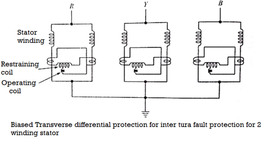
An inter-turn fault occurring on the same phase of the stator winding do not disturb the neutral current, hence by the use of longitudinal differential relay it is not possible to detect such type of fault. This results to another modification in the protection designing whereby we make the transverse differential relay in case of the generators where the stators have two windings per phase. The protection scheme is given as
Q6) Write short notes on Rotor Protection & Loss of Excitation Protection?
A6) Rotor Protection
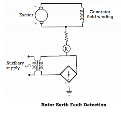
The rotor windings as discussed earlier may be due to earth faults or open circuits. The figure shows a modern method of rotor earth fault detection. The field is biased by a dc voltage which causes current to flow through R for an earth fault.
Loss of Excitation (Field Failure) Protection
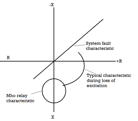
The loss of field circuit imposes the circuit to draw reactive VAR from the system. This results in machine being operated as an induction generator. This causes overheating in the circuit. Loss of excitation is detected by the import of VAR indicating either actual or prospective loss of synchronism. So the transients in such phenomena can be allowed for 1 to 5 seconds in tripping sequence of the relay. Due to the loss of excitation, there would be a drop in voltage and resulting in the drop of current. This can be detected by an undercurrent moving coil relay in the field circuit. Even this method is not suitable for generators having wide range of operation in the field excitation. The alternative solution that can be implemented is to apply an offset impedance or mho relay. Its operating characteristics are arranged so that during conditions of low excitation the effective generator impedance falls in the tripping zone.
Q7) Explain the concepts of Motor protection with Stator & Rotor Protection?
A7) The motor acts as the important loads in the power system as they compose mostly 90% of the loads. The protection of these apparatus becomes very important. The motors that are taken into consideration are synchronous and induction motors. Types of Faults The faults that occur mostly in the motor are almost similar to that of the generators. The faults can be classified as:
(a) Stator Faults
(b) Rotor Faults
(c) Overloads
(d) Unbalanced supply voltages including single phasing.
(e) Under voltage
(f) Reverse or open phase starting
(g) Loss of synchronism
Stator Protection
The faults that occur in the stator can be either between phases or to the earth. The protection of the motors against these faults can be done by the help of over current tripping device which would give an inverse time-current characteristics.
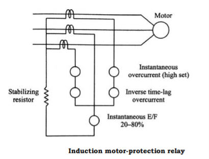
Phase fault protections are provided by two high-set instantaneous relay elements; the current setting is chosen above the maximum starting current. Earth fault protection is provided in a motor operating on an earthed neutral system by using a simple instantaneous relay having a setting of approximately 30% of the full load current. Since the earth fault relay shouldn’t trip at the initial switching due to CT saturation of high starting current, so the voltage setting of the relay is increased by inserting a stabilizing resistance in series with it. The scheme can be described as below
Rotor Protection
Any unbalance in the supply or in the loading pattern will cause high amount of negative sequence current in the stator. This induces high frequency currents in the rotor circuit also. The frequency of this current is (2-s) times the normal frequency. The heating value of the negative sequence current is high as compared to positive sequence current, which is proportional to (2-s) f (approximately 100 Hz) a.c. Resistance value. Hence motor protection must be taken into account the allowable voltage unbalance without overheating.
Q8) Write short notes on Overload, Unbalance & Single Phasing protection of a motor?
A8) Overload Protection
The overload protection of the motor is designed so as to match the heating curve of the motor. The motor must not be allowed for most of the time for heating. For this reason the characteristics of the relay must not be more than the heating characteristics of the motor for protection. The protection must also have the capability to adjust its characteristics and should not allow the motor to restart until the motor winding temperature is high. For this reason the IDMT relay is best suited for this purpose.
Unbalance and Single Phasing Protection
An unbalance in the system causes the negative sequence currents to flow in the motor. This would result in overheating of the machine windings. Unbalanced loads or accidental opening of one phase of the supply (single phasing) depending on the load still keeps the motor running with the induction of negative sequence in the motor.
For star connected motors the unbalance can be protected by two overload elements. For delta connected motors such arrangement is satisfactory when the motor is running for more than 70% of the full load.
Q9) Write short notes on Under Voltage & Reverse Phase protection?
A9) Under voltage Protection
A motor working in over voltage situation would generally be associated with over current and thus can be protected by overload devices. A time delay is generally given to avoid transient behavior of the voltage drop.
Reverse Phase Protection
The direction of rotation of the motor changes if the phase sequence is changed. In some motors this becomes very important. In order to ensure the direction of rotation an induction disc, poly phase voltage relay is used to protect the motor from starting when there is a mismatch of the sequence. Such a connection is shown in the figure below, where the torque is proportional to the sine product of two voltages. So when there is a mismatch of sequence, there would be no torque and restrains the motor from operating.
Q10) What are the different types of faults in bus zone?
A10) The faults in the bus zone can be divided as follows:
(i) Failure of circuit breaker to interrupt fault current or failure to clear under through fault conditions.
(ii) Insulation failure due to material deterioration.
(iii) Flashover causes by prolonged and excessive over voltages.
(iv) Errors in the operation and maintenance of switchgears.
(v) Foreign objects accidentally falling across bus bars
Bus Backup Protection
When no separate protection is provided for the bus bars but there is a provision of distance protection, so any fault that is occurring at the bus zone protection would come under the zone 2 protection of the distance relay where it covers the bus bar and the next line also. This is satisfactory for the small switchgear case but not in the case of prime installations. Therefore a separate bus zone protection may be provided for the same.
Q11) Explain the Differential scheme of Bus Bar Protection?
A11) It is based on the simple circulating current principle that during the normal condition or external fault condition, the incoming current must be equal to the leaving current. Since the bus in a power system acts as a node in an electrical circuit, if the summation of currents is not equal to zero, it means that there is a short circuit due to ground fault or phase to phase fault. The differential scheme can be given as below, whose CT ratio are given according to the highest current that is flowing in the feeder circuits.
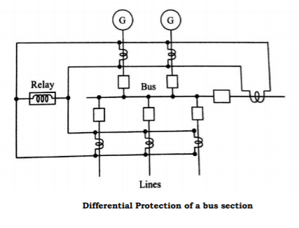
Since the CTs used here are of the same ratio, when there is a through fault condition, the magnetic conditions of the iron cored CTs would result in false operation due to saturation. Even with biasing of the relay, the improvement is not satisfactory. An improvement can be done by the use of non iron cored CT also known as linear coupler to overcome the difficulties of iron cored CTs. In this the secondary voltage is proportional to the primary current. So when there is an external fault, the addition of the voltages won’t result to zero since the current is still balanced, but when there is an internal fault there is an unbalance in current and hence results to some voltage in the linear coupler scheme.
Frame Leakage Protection
It is possible to design a station so that the faults which develop are mostly earth faults, by providing earthed metal barrier surrounding each conductor in the bus structure. With this arrangement every fault that might occur must involve a connection between the conductor and an earthed metal part. The figure below shows the metal supporting structure also known as a fault bus earthed through a CT. Sometimes, the structure is earthed by the means of impedance connected in the neutral.
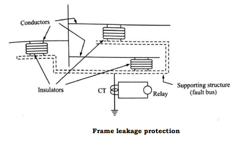
In the resistance earthed neutral, the advantage is that besides limiting the value of current it is also used to protect certain part of the generator or transformer windings which are connected in the feeder circuits. The earth fault current for protecting x% of the winding is given as

This must be also the primary fault setting of the differential protection IS for minimum operating current.

Or % winding unprotected is

Q12) What are Numerical Relays & draw its architecture?
A12) Numeric relays are the evolved form of a static and electromagnetic relay. They are basically a device used for measuring electric parameters in an electrical network and convert them into numerical data which undergoes mathematical and logical analysis to decide on tripping an electrical network.
The main purpose of a numerical relay is to protect the electrical network from unexpected fault currents. Numerical relays are mostly preferred because of their versatile characteristics. A single Numerical relay can monitor multiple parameters like current, voltage, Frequency, onset time, offset time, etc. And the same relay can be used for analyzing and monitoring multiple faults such as over current, over fluxing, different current and more. Numerical relays are based on digital technology, they are more or less immune to variation or drift in parameters of individual components like OP-AMPS etc. due to changes in temperature, ageing etc. Numerical relays also help in reducing burden (volt-amperes) of Current Transformer (CT) and Voltage Transformer (VT). This is desirable because ideally sensors should not consume any power. If a sensor consumes energy from the measurand, it will automatically distort the signal. This problem is further aggravated in CTs due to non-linearity of iron core. Numerical relays offer very low impedance to the secondary of CT and hence reduce burden on CT.
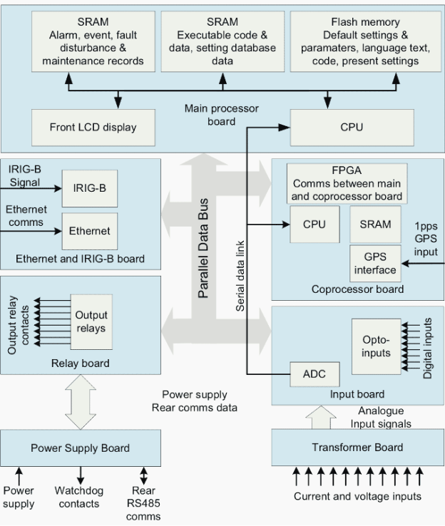
Block Diagram of Numerical Relay
The numeric relay can be called as a miniature computer as they both have similar hardware architecture with slight differences.
Q13) What are the major components of Numerical Relays?
A13) This relay contains the following major components-
Input Module
The Power system operates with analog parameters. The high powered analog signals are stepped down with current transformer and Potential transformer. It is fed to the numeric relay using lowpass filter. The low pass filter is used to eliminate the noisy signal in the system due to corona or induction effect from a nearby high voltage line.
CPU
Central Processing Unit (CPU) is the brain of the system, which processes all data protection algorithm and digital inputs and their filtering.
Memory
Numerical relay has two memories, RAM and ROM. Random Access Memory (RAM) is responsible for retaining the input data to the relay and processing the data during compilation. Read-Only Memory (ROM) is the storage unit of the relay. It stores the software needed and other data related to event and disturbance. The Storage unit is a must feature because it helps in analyzing and troubleshooting any event during the occurrence of a fault.
Multiplexer and Analog to digital converter
The CPU can only process digital data but the input from the current transformer and potential transformer are analog. Hence the Analog to digital converter is used to convert the signal to digital data. In case multiple analog signals need to be converted a multiplexer is used for selecting the required analog input for conversion.
Q14) Explain the Output Module, Digital Input for communication in mobile under Numerical Relays?
A14) The output module is the digital contacts that are actuated when a trip command is given by the CPU. These digital contacts are pulses that are generated as a response signal. The response time can be changed according to the application of the relay.
Digital input/Communication module
As of in a computer, a relay also has serial and parallel ports for connecting the relay with control and communication systems in the substation. The Auxiliary relays can be connected to the digital output contacts to extend the tripping command.
Q15) Explain the concept of Signal Sampling & Processing of Data?
A15) Sampling the filtered signal and anti-aliasing
In order to avoid the anti-aliasing (high frequency component will appear as low frequency), the minimum sampling frequency shall be selected so that, it is at least double that of the highest frequency component of interest. Suppose we are interested in finding out the 5th harmonic component in 50 nHz system, we should have minimum of 500 Hz as sampling frequency. A frequency of 800 Hz or more is usually set by different manufactures to sample the data
Processing of the data
The sampling and processing of the data is done in the DSP (Digital signal processor) in case of numerical IEDs. This processing of such sampled data is called Relay Algorithm, Relay Algorithm is pre-programme done inside the Relay so that different protection functions can be processed according to the requirement. For example, in a relay that uses over current protection as one of its functions will have an over current algorithm running to check whether an over current situation has arisen in the system. Similarly, when a distance or differential protection is activated inside the relay, it starts executing the algorithm for the same.
Q16) What is the Numerical Over Current Protection?
A16) Over current/Earth fault relays are the basic protection relays. Used for protection of transformers and feeders from over current and earth faults. When excessive current flows in a circuit, it is necessary to trip the circuit breaker protecting that circuit. It is operated when the fault drives the power to flow in a particular direction (Opposite to the specified direction). Used in the protection of Bus bar, Generator, and Transformers.
The Example Over current/Earth fault relay is shown in the below figure. It is the most common Numerical relay. The following protection functions are used in this relay.
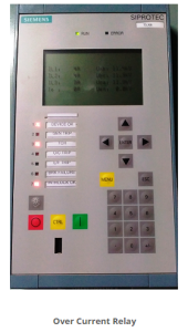
Protection Functions used in this relay are
- 50/51 Phase Over Current Protection- Definite time/Time over Current IEC
- 50N/51N Earth over Current Protection- Definite time/Time over Current IEC
- Ground Fault Protection- Definite time/Time over Current IEC
Sensitive Earth Fault protection is provided by using CBCT - 74Trip circuit Supervision- With 2 Binary inputs/With 1 Binary input
- Breaker Failure
Q17) Explain of over current protection?
A17) Over current relay protection is usually provided by either instantaneous or time delay over current relays.
Instantaneous Over current Protection (50):
This is typically applied on the final supply load or on any protection relay with sufficient circuit impedance between itself and the next downstream protection relay.
Q18) Explain the basic concept behind Numerical Transformer Differential Protection?
A18) Differential Protective Relay is a protective relay that functions on a percentage or phase angle or other quantitative difference of two currents. Differential relaying provides selectivity by providing a zone of protection with a circuit of interconnected CT’s. CT’s having the same ratio are installed in all the connections to the component (Example Transformer) to be protected and the secondary of the CT’s are connected in parallel to the relay.
The differential relay is set to trip when the phase difference of two or more identical electrical quantities exceeds the specified value. It can protect Transformers and Generators from localized faults.
As long as the current flow through the protected component is unchanged in magnitude and phase, the relay does not pick up. Such a condition would occur for a short-circuit fault outside the zone of relay protection. Should a fault occur inside the zone of relay protection (that is between the CT’s), the differential relay would receive current in the operating coil.
The example differential protection relay shown in the below figure is a transformer differential relay. The following protection functions are used in this relay.
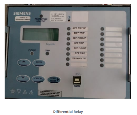
Differential Protection comprises both biased differential and high-set differential functions.
Q19) What are the different types of settings used when there are no interposing CT’s used in the circuit?
A19) 1. Internal Current Multiplier:
Line CTs are used to measure fundamental frequency currents. These line currents need to vector corrected before applying to the differential elements.
The multiplier is used to correct any CT ratio mismatch so that ideally nominal current is applied to the biased differential algorithm.
2. Internal Interposing Current Vectors:
ICT Vector setting applies the correct vector compensation to the current applied to the differential algorithm. Means the phase change introduced due to transformer connections is nullified using this setting.
Q20) What are the advantages of Numerical Relays?
A20) Advantages of Numerical Relays
1. Compact Size
In the case of electromechanical relay, there is a need for mechanical comparison devices. This amounts for the bulky size of the relay. Then, there is a need for a flag system for activation confirmation of relay.
As opposed to this, the numerical relay relies on one system for all approach and use indication on LCD for relay activation, ensuring less space.
2. Flexibility
Since the numerical relay system relies on software, customized modifications can be made for getting the desired protection features. This saves you the cost of replacing hardware.
3. Reliability
One basic problem with electromechanical relays is that because of larger components and mass interconnection, component non reliability can be an issue. In the case of numerical relays, fewer interconnections ensure reliability.
4. Multiple relay characteristics
The range of operation of traditional models is narrow while numerical relays are diverse and evolution adaptable. This property of multitasking is further strengthened on the account that the numerical system can accommodate different types of relay characteristics.
Since, it is possible to provide better compatible protection characteristics, the efficiency improves. This is achieved with the memory save feature in the microprocessor.
5. Communication capacity
Among the most significant advantages of a numerical relays is its ability to cater to digital communication. An interface is added which brings microprocessor-based relay property. Substation LAN coupled with fibre optics complete the communication capacity.
The property is directly linked to the data history feature of the numerical relay system. Because of data storage systems, the availability of fault data and disturbance record can be made. This helps in finding the nature/magnitude/duration of the fault.
6. Auto reset
It has also been highlighted how the system is flexible. In addition to this, it also has the feature of auto resetting and self-diagnosis.
As opposed to numerical relay systems, electromechanical systems do not have the ability to check if normal condition has been attained once activated. The self-diagnose and self-reset features provide less dependence on operating personnel.
7. Related benefits
Apart from the mainstream benefits that have been provided above, there are other ones too. For instance, there is a modular frame in the numerical relay system which allows ease of service.