Unit - 1
Three Phase Synchronous Machines
Q1) Explain Coil span factor
A1)
Coil span factor or pitch factor-
The distance between the two sides of a coil is called the coil span or coil pitch.
The angular distance between the central line of one pole to the central line of the next Pole is called pole pitch. A pole pitch is always 180 electrical degrees regardless of the number of poles on the machine.
A coil having a span equal to 180° electrical is called a full pitch coil.
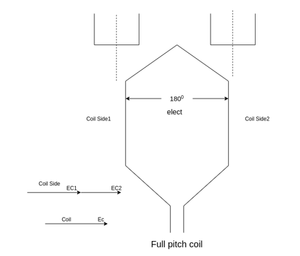
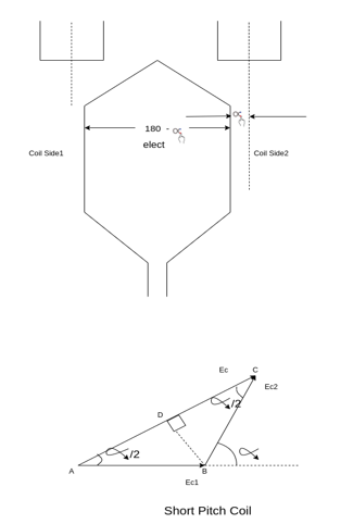
A coil having a span less than 180° electrical is called a short pitch coil, for fractional pitch coil. It is also called a chorded coil. A stator winding using fractional pitch coils is called a chorded winding. If the span of the coil is reduced by an angle  electrical degrees, the coil span will be (
 ) Electrical degrees.
The coil span factor or pitch factor  is defined as the ratio of the voltage generated in the short pitch coil to the voltage generated in the full pitch coil. The coil span factor is also called the chording factor.


For full pitch coil,  , and
, and
 For short pitch coil
Q2) Explain Distribution factor.
A2)
Distribution factor or breadth factor  -
-
In a concentrated winding, the coil side of a given face is concentrated in a single slot under a given Pole. The individual coil voltage is induced and is in phase with each other. These voltages may be added arithmetically.
In actual practice, in each phase comic walls are not concentrated in a single slot but are distributed in a number of slots in space to form a polar group under each pole.
The voltages induced in a coil side constituting a polar group are not in the face but differ by an angle equal to the angular displacement of the slots.
The distribution factor or bread factor is defined as the ratio of the actual voltage obtained to the possible voltage if all the coils of a polar group were concentrated in a single slot.

Let m=slots per pole per phase

 = Angular displacement between adjacent slots in electrical degrees


It is to be noted that the distribution factor  for a given number of phases is dependent only on the number of distributed slots under a given pole. It is independent of the type of winding, lap or wave, or the number of turns per coil, etc.
Q3) Define Voltage regulation of alternator and draw the equivalent circuit of the alternator.
A3)
The voltage regulation of a synchronous generator is the rise in voltage at the terminals when the load is reduced from full load rated value to zero, speed and field current remaining constant.
It can be written as
Per unit voltage regulation
Percent voltage regulation
Where  =magnitude of generated voltage per phase
|V|= magnitude of rated terminal voltage per phase
The voltage regulation depends upon the power factor of the load. For unity and lagging power factor, there is always a voltage drop with the increase of loads but for a certain leading power, the full load voltage regulation is zero. In this case, the terminal voltage is the same for both full load and no load conditions. At lower leading power factor, the voltage rises with the increase of load and the regulation is negative.
Equivalent circuit of a synchronous generator
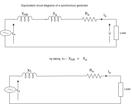
Q4) Derive the EMF equation of three phase synchronous generator.
A4)
EMF equation-
Let  =useful flux per pole in weber
P=total number of poles.
 =total number of conductors or equal sides in series per phase.
 =total number of coils or turns per phase.
n=speed of rotation of rotator is revaluation per second.
F=frequency of generated voltage.
Since the flux per Pole is  , each stator conductor cuts a flux
  .
.
The average value of generated voltage per conductor
=(
Since n revolutions are made in one second, one revolution will be made in 1/n second. Therefore, the time for one revolution of the armature is 1/n second. The average voltage generated per conductor is


Since there are  conductors in series per phase, the average voltage generated per phase are given by

Since.

For the voltage wave, the form factor is given by

For sinusoidal voltage KF=1.11


Above equation has been derived with the following assumptions
a) Coils have got a full pitch
b) All the conductors are concentrated in one stator slot.
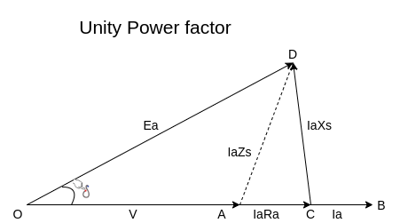
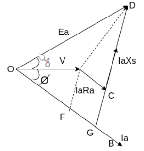
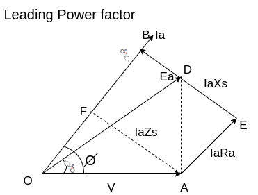
Q5) Draw Phasor diagram of Salient-pole generator and emf equation.
A5)
Equivalent circuit, and phasor diagram of a synchronous generator
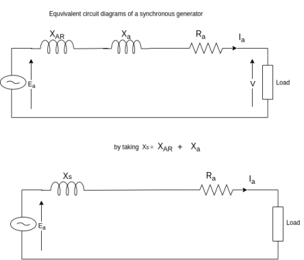
a) Unity power factor


b) Lagging power factor


c) Leading power factor


Q6) A 3-phase, 50Hz, 8 pole alternator has a star connected winding with 120 slots, and 8 conductors per slot. The flux per Pole is 0.05 WB. Sinusoidally distributed. Determine the phase and line voltages.
A6)
The full pitch coil


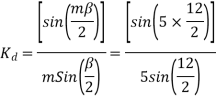
=0.9567
Total number of conductors=conductor per slot×number of slots
Z=8×120=960
Conductors per phase 

Generated voltage per phase


Generated voltage line


Q7) A 3 phase 6 pole star connected alternator revolves at 1000 r.p.m. The stator has 90 slots and 8 conductors per slot. The flux per Pole is 0.05 wb (Sinusoidally distributed). Calculate the voltage generated by the machine if the winding factor is 0.96.
A7)

Total number of stator conductors=conductors per slots×number of slots
=8×90=720
Stator conductors per phase


Generated voltage per phase


Generated line voltage=


Q8) Compare Salient-pole type and non-salient-pole type.
A8)
Sr. No. | Salient pole type synchronous machine | Non-salient pole type synchronous machine |
1 | Diagram 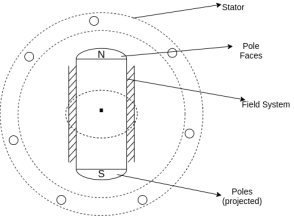
| Diagram 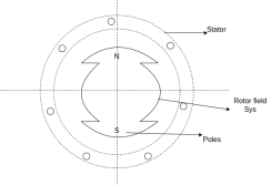 |
2 | Projected out poles | Merged in polls |
3 | Rotor surface is projected | Smooth rotor surface |
4 | The diameter of the machine is large | The small diameter of the machine |
5 | The axial length of the machine is small | The axial length of the machine is large |
6 | Speed is slow | Speed is high |
7 | Air gap is non uniform | Air gap is uniform |
8 | Damper bars/winding is used | Damper bar/winding not used |
9 | The air gap between stator and rotor is non-uniform | The air is uniform between stator and rotor |
10 | Centrifugal stress is more | Centrifugal stress is less |
11 | Aerodynamic resistance is more | Aerodynamic resistance is less |
Q9) Explain armature reaction and its effect under different load power factors.
A9)
Armature reaction
The effect of armature flux  on the flux produced by the field poles or the main flux
  is called armature reaction.
This effect is different for different nature of p.f. Of the load.
1) The effect may be cross magnetizing i.e.,
2) It may be strong magnetizing or magnetizing i.e., is in the same direction as
  , So both are added, and the resultant field becomes stronger.
3) It may be demagnetizing i.e.,  , and hence
  weakens.
Different nature of p.f.
1) Unity PF
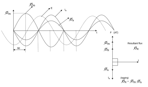
2) Zero PF lagging
3) Zero PF leading
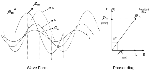
Unity PF-: in this case  is in phase with E.
Phasors relations: -
1) E lag 
2)  in phase with E
3) Field ampere-turns i.e., F and 
4) Flux produced by  in phase with
  that is
The armature flux  crosses the main flux
  from the winding field, and vector diagram or Phasors.
Also, the armature flux crosses the resultant flux so for the unit PF the armature reaction is such that the main flux  is crossed or distorted. It is a cross magnetizing effect.
Zero lagging PF
It is seen that for lagging PF the armature flux is in direct opposition to flux  Hence it is demagnetizing, and resultant flux
Hence in the case of lagging PF, the effect of armature reaction is demagnetizing.
Q10) Explain armature reaction as per Blondel’s two-reaction theory for salient-pole machines.
A10)
Two reaction theory
Two reaction theory was proposed by, Andre Blondel. The theory proposes to resolve the given armature mmfs into two mutually perpendicular components, with one located along the axis of the rotor salient pole. It is known as the Direct axis component. The other component is located perpendicular to the axis of the rotor salient pole. It is known as the quadrature axis component. The d axis component of the armature MMF  is denoted by
  , and the q axis component by
  The component
  is either magnetizing or demagnetizing. The component
  results in a cross-magnetizing effect.
If  is the angle between the armature current
  , and the excitation voltage
  is the amplitude of the armature MMF, then

And 
Salient pole synchronous machine two reaction model
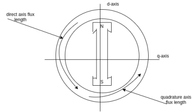
In the cylindrical rotor synchronous machine, the air gap is uniform. The protruding pole structure of the rotor of a salient pole machine makes the air gap highly non-uniform. Consider a two-pole rotor rotating in the anticlockwise direction within a two-pole stator.
The Axis along the axis of the rotor is called the d axis, and the axis perpendicular to the d axis is called the quadrature axis.
It is seen that the direct Axis flux path involves too small air gaps, and is the path of minimum reluctance. The path denoted by has too large air gaps, and is the path of maximum reluctance.
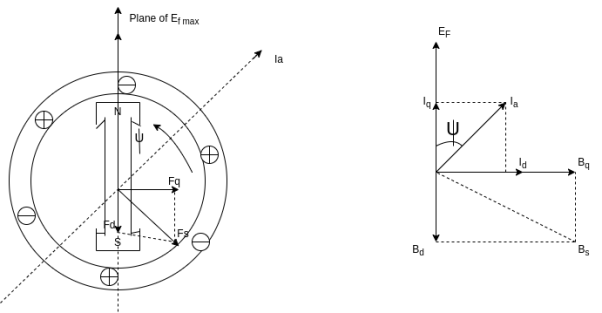
The rotor flux  is shown vertically upwards, this rotor flux induces a voltage
  in the stator.
If a lagging p.f. The load is connected to the synchronous generator, a stator current  will flow, and it lags behind the generated voltage
  by an angle
  .
.
The armature current produces stator mmf  which will lags behind
  by 90°. The stator MMF
  produces a magnetic field
  along its direction, and it can be resolved into two components the Direct axis component
  , and the quadrature axis component
Q11) A 3 phase 16 pole alternator has a star connected winding with 144 slots, and 10 conductors per slot. The flux per pole=0.03 wb sinusoidal distributed, and speed is 375 rpm.
Find Frequency, Phase voltage, Line voltage.
A11)

Total conductors= 144×10=1440


For  as coil pitch is not mentioned take full pitched coil.
 =1
=1


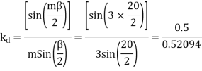


For star connection,

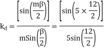
Q12) A 3 phase 4 pole alternator has 60 slots, two conductors per slot. The pitch of the coils is 3 slots less than full pitch. Find Kc and Kd.
A12)
Pole pitch=
Now 15 slots=180




Q13) A single 50 Hz synchronous generator on droop control was delivering 100 MW power to a system. Due to increase in load, generator power had to be increased by 10 MW, as a result of which, system frequency dropped to 49.75 Hz. Further increase in load in the system resulted in a frequency of 49.25 Hz. At this condition, the power in MW supplied by the generator is _______.
A13)
Given: f=50Hz
P=100Mw
Using 
For 1st Case:


Using equation (i)
For 2nd Case: 

Using equation (i)
 (iii)
(iii)
Dividing (iii) by equation (ii)


So 

Q14) A cylindrical rotor synchronous generator has steady state synchronous reactance of 0.7 pu and sub transient reactance of 0.2 pu. It is operating at (1 + j0) pu terminal voltage with an internal emf of (1 + j0.7) pu. Following a three-phase solid short circuit fault at the terminal of the generator, the magnitude of the sub transient internal emf is ________ pu.
A14)


For a solid 3- fault,
Now sub transient internal emf


Q15) A cylindrical rotor synchronous generator with constant real power output and constant terminal voltage is supplying 100 A current to a 0.9 lagging power factor load. An ideal reactor is now connected in parallel with the load, as a result of which the total lagging reactive power requirement of the load is twice the previous value while the real power remains unchanged. The armature current is now_______ A.
A15)
Given


Real power  constant
So, 
 Terminal voltage remains constant]


From equation (i)


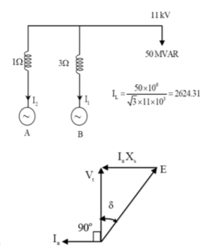
Q16) Two parallel connected, three-phase, 50Hz, 11kV, star-connected synchronous machines A and B, are operating as synchronous condensers. They together supply 50 MVAR to a 11 kV grid. Current supplied by both the machines are equal. Synchronous reactance of machine A and machine B are and respectively. Assuming the magnetic circuit to be linear, the ratio of excitation current of machine A to that of machine B is ________.
A16)
 syn. Condenors
 current’s supplied boththe machines are same

As the two motors, supplying reactive power only, the phasor diagram will be


Consider magnitudes 




Q17) A 3-phase, 2-pole, 50 Hz, synchronous generator has a rating of 250 MVA, 0.8 pf lagging. The kinetic energy of the machine at synchronous speed is 1000 MJ. The machine is running steadily at synchronous speed and delivering 60 MW power at a power angle of 10 electrical degrees. If the load is suddenly removed, assuming the acceleration is constant for 10 cycles, the value of the power angle after 5 cycles is ________ electrical degrees.
A17)


 cycles

New ration, δ=10+2.7=12.7
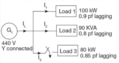
Q18) For the circuit given below, what real and reactive power are provided by the generator when the switch is closed?
A18)


Total real power 
Total reactive power=52.8 KVAr
Q19) A 25 kVA, 400 V, - Δ-connected, 3-phase, cylindrical rotor synchronous generator requires a field current of 5A to maintain the rated armature current under short-circuit condition. For the same field current, the open-circuit voltage is 360V. Neglecting the armature resistance and magnetic saturation, its voltage regulation (in % with respect to terminal voltage), when the generator delivers the rated load at 0.8 pf leading, at rated terminal voltage is _________.
A19)


Q20) A 30MVA, 3-phase, 50Hz 13.8kV, star-connected synchronous generator has positive, negative and zero sequence reactance, 15%, 15% and 5% respectively. A reactance (Xn) is connected between the neutral of the generator and ground. A double line to ground fault takes place involving phases ‘b’ and ‘c’, with a fault impedance of j0.1 p.u. The value of Xn (in p.u) that will limit the positive sequence generator current to 4270 A is ________.
A20)


