Unit - 3
Three Phase Synchronous Motor
Q1) Explain operation of synchronous motor at constant load & variable excitation.
A1)
Effect of varying field current
For simplicity armature resistance  is neglected. Synchronous reactance
  and terminal voltage V are assumed constants. The power per phase is given by

Since V and  are constants, therefore for constant power output
  and
and  should remain constant. That is


Also, 
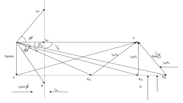
When the field current increases the magnitude of  increases, but the component of
  normal to V, that is,
  must remain constant.
It is seen that as  varies,
  and therefore the armature current
  also very subject to the condition that
  remains constant.
When  is varied slowly enough to avoid hunting,
  where is in magnitude and the tip of
  phases move along the constant power locus CD so that
  remains constant.
Since 
And 
The above equation shows that the restricted variation of  (that is
  equal to a constant), the armature current
  also varies with the constraint that
  remains constant. The tip of the
  phasor moves along the constant power locus AB so that
  remains constant. Also, the phasor
  must always remain perpendicular
  drop as the tip of the current phasor
  moves along its locus.
These three constraints


And  is perpendicular to
  enable us to draw the phasor diagram of a synchronous motor for varying field currents.
The figure shows the phasor diagram for lagging PF, unity PF, and leading PF.
It is seen in phasor diagram that as the value of  increases, the magnitude of the armature current first decreases and increases again. The armature current is minimum at unity PF and more at leading or lagging power factors.
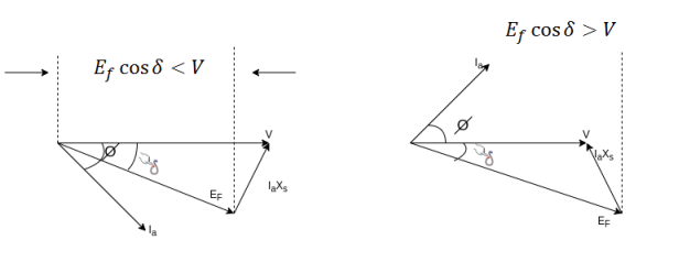
When  is small the armature current is lagging and the motor is an inductive load. It acts like an indicator resistor combination, consuming reactive power Q
As the field current is increased the armature current  becomes in phase with the terminal voltage V and the motor becomes a purely resistive load.
As the field current is increased further the armature current  becomes leading and the motor becomes a capacitive load. It acts as a capacitor resistor combination consuming negative reactive power -Q or alternately supplying reactive power +Q to the system.
So when


Q2) Compare 3 phase synchronous motor with 3 phase induction motor.
A2)
Sr. No. | Synchronous motor | Induction motor |
1 | Construction is complicated | Simple construction particularly in case of cage rotor motor. |
2 | Not self starting | Self starting |
3 | Separate DC source required for rotor excitation | Rotor excites by the induced EMF. Separate force is not required |
4 | The speed is always synchronous irrespective at load. | Speed is always less than synchronous speed and never synchronous speed |
5 | Speed control is not possible | Speed control is possible though it is different. |
6 | As load increases, the load angle increases, keeping the speed constant as synchronous | As load increases the speed decreases. |
7 | By changing excitation, the PF can be changed from lagging and leading | It always operates at lagging PF and PF control is not possible. |
8 | It can be used as synchronous condenser for PF improvement. | It can't be used for PF improvement. |
9 | Motor is sensitive to sudden load changes and hunting effect | Phenomenon of hunting is absent. |
10 | Motor is costly and requires frequent maintenance | Motors are less costly and cage motors are housing less maintenance |
Q3) Explain briefly ‘v’ curves & inverted ‘v’ curves in case of 3 phase synchronous motor.
A3)
Synchronous motor v curves
It has also been observed that the armature current  changes with change in field current
  Let us assume that the motor is operating at no load. If the field current is increased from this small value of the armature current
  decreases until the armature current becomes minimum. At this minimum armature current the motor is operating at unity power factor. Up to this point the motor was operating at a lagging power factor. If the field current is increased further, the armature current increases again at the motor starts to operate at a leading power factor. If a graph is plotted between armature current
  and field current
  at no load the lowest curve is obtained. If this procedure is repeated for various increased loads, a family of curves is obtained as shown.
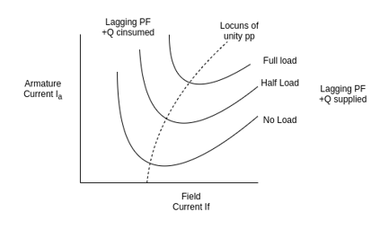
This V curves are plots of stator current versus field current for different constant loads.
Inverted V curves:
A family of curves is obtained by plotting the power factor versus field current. These are inverted V curves as shown in figure below.
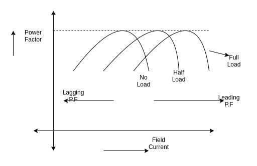
The highest point on each of these curves indicate unity power factor. The field current for unity power factor at full load is more than the field current at unity power factor at no load.
Q4) Explain in detail methods of starting.
A4)
Methods of starting-
Synchronous motor starting the synchronous motor must be brought to a speed sufficiently close to synchronous speed in order to lock into synchronism with the rotating field
- DC motor coupled to the synchronous motor shaft- this method sometimes used in Laboratories with synchronous Motors not equipped with damper winding generally the synchronous motor is intended as the constant speed Prime mover for the DC generator. But in order to bring the motor up to synchronism, the decision letter is operated as motor. The DC motor will now act as a generator if its field current is increased so that its generated EMF exceeds the DC bus.
- Using field excited generator as a DC motor-
- A small induction motor of at least one pair of poles less than the synchronous motor-this method in involve the same synchronizing procedure for AC synchronous motor as an alternator.
- Using the damper winding as a squirrel cage induction motor- it is practically impossible to start a synchronous motor with its DC field energized. Even when left to de-energized, the rapidly rotating magnetic field of the stator will induce extremely high voltages in the many turns of the field winding. Therefore, it is customary to short circuit the DC field winding during the starting period, whatever voltage and current are induced in it, it may then aid in producing induction motor action. In very large synchronous motors, field sectionalizing or field splitting switches are used with short circuit individual field windings to prevent cumulative addition of induced voltage is from pole to pole.
Q5) Explain terms Lock rotor torque, running torque, Pull-in, Pull-out torques.
A5)
Different torques in synchronous motor
1) Locked rotor torque- it is the minimum torque at any angular rotor position that is developed with the rotor locked (stationary) and rated voltage at rated frequency is applied to the terminals. This torque is provided by the stator windings.
2) Running torque- It is the torque developed by the motor under running conditions. It is determined by the power rating and speed of the driven machine.
3) Pull in torque- A synchronous motor is started as induction motor till it runs to 2 to 5 % below the synchronous speed. The DC excitation is then applied and the rotor pulls in to step with the synchronously rotating stator field. The pull in torque is the maximum constant torque at rated voltage and frequency under which a motor will pull a connected load into synchronism when the DC motor excitation is applied.
4) Pull out torque- It is the maximum value of torque which a synchronous motor can develop at rated voltage and frequency without losing synchronism.
Q6) A 3 , 400V synchronous motor takes 52.5 A at a power factor of 0.8 leading. Determine the induced EMF and power supplied. The motor impedance per phase is
  .
.
A6)
Given  ,
, 


Line emf =  * Induced Emf

Power supplied =>


Q7) A 2.3 KV,  , star connected synchronous motor has
  . The motor is operating at 0.5 P.F. Leading, with a line current of 200 A. Determine the generated Emf per phase.
A7)


Line EMF= Induced EMF
Line EMF =
Line emf=2.9583KV
Q8) Explain in brief phenomenon of hunting.
A8)
Hunting or phase swinging
When synchronous motor is loaded, the rotor falls back by an angle  (called as load angle). Even if rotor falls back by
  it continues to rotated at synchronous speed i.e., speed of the stator magnetic field.
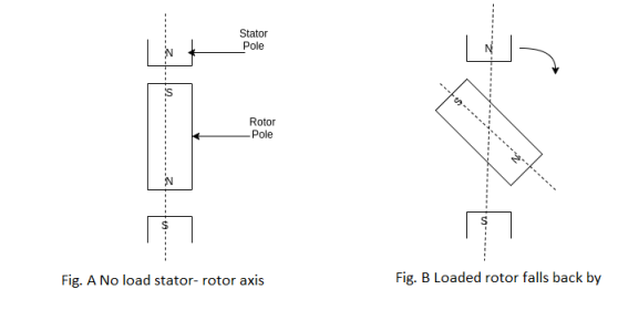
So, for first figure a  & for figure b
  is having some angle and value. But in actual case, the rotor does not settle to angle
  immediately i.e., when motor is loaded there are several oscillations of rotor around the final
  position. This is due to the inertia of the rotor. These oscillations are called hunting in synchronous motor.
Due to hunting the load angle  changes its value about its final equilibrium value.
Causes of hunting:
1) Sudden changes of load.
2) Fault occurring in the system which the generator supplies.
3) Sudden changes in the field current.
4) Cyclic variations in or of the load torque.
Effects of hunting:
1) It can be lead to loss of synchronism.
2) Variations of supply voltage producing undesirable lamp flicker.
3) Increases the possibility at resonance.
If the frequency of load torque component becomes equal to that of transient oscillations the resonance occurs.
4) Large mechanical stress on rotor shaft.
5) Increases in machine losses and temperature.
Remedies/ reduction of hunting:
1) By using the damper winding.
2) By using the fly wheels
Q9) Explain role played by damper winding in case of synchronous motor during.
A9)
3 phase armature winding is on the stator and is wound for the same number of poles as the rotor.
The rotor of a synchronous motor can be of the salient pole or cylindrical pole type of construction. Generally, it is of salient pole type, except for exceedingly high speed machines.
An additional set of winding called the damper winding is mounted on the rotor. This winding is placed in slots located in the pole faces and parallel to the shaft.
The ends of the copper bars are short circuited in the same manner as in the case of rotor of an induction motor.
Damper winding provides a means of starting to the synchronous motor. They also serve to increase the stability of the motor during load transients.
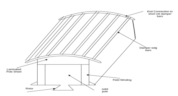
Using the damper winding as a squirrel cage induction motor- it is practically impossible to start a synchronous motor with its DC field energized. Even when left to de-energized, the rapidly rotating magnetic field of the stator will induce extremely high voltages in the many turns of the field winding. Therefore it is customary to short circuit the DC field winding during the starting period, whatever voltage and current are induced in it, it may then aid in producing induction motor action. In very large synchronous motors, field sectionalizing or field splitting switches are used with short circuit individual field windings to prevent cumulative addition of induced voltage is from pole to pole.
Q10) Write about Starting condition, Running condition, Load changes under running condition.
A10)
Effect of load changes on a synchronous motor
Synchronous motor runs at absolutely constant synchronous speed, regardless of the load.
Consider a synchronous motor operating initially with a leading power factor. Suppose that the load on the shaft is increased. The rotor slows down momentarily since it takes some time for the motor to take increase power from the line. In other words, although still rotating at synchronous speed, the rotor slips back in space as a result of increased loading. In this process the torque angle  becomes larger and therefore the induced torque
  Increases. The increased torque increases the rotor Speed the motor again picks up the synchronous speed but with a larger torque angle
Since the excitation voltage  is proportional to
  it only depends upon the field current and the speed of the motor.
Since the motor is moving with a constant synchronous speed, and since the field circuit is also untouched, the field current remains constant.
Therefore, the magnitude of excitation voltage  remains constant with the change in load on the shaft.


Where 
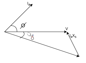
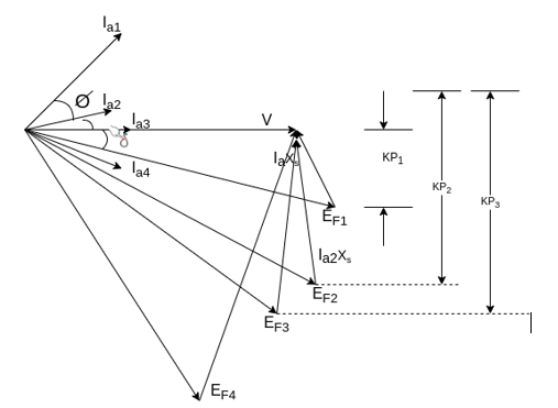
Thus, when the load on a synchronous motor is increased,
1) The motor continues to run at synchronous speed.
2) The torque angle  increases.
3) The excitation voltage  remains constant.
4) The armature current  drawn from the supply increases.
5) The phase angle  increases in the lagging direction.
Q11) Write applications of three phase synchronous motor.
A11)
The important characteristics of the synchronous motor are its constant speed irrespective of the load conditions and variable power factor operation. Due to constant speed characteristics it is used in
- Machine tools
- Motor generator sets
- Synchronous clocks
- Stroboscopic devices
- Timing devices
- Belt driven reciprocating compressors
- Fans and blowers
- Centrifugal pumps, vacuum pumps
- Pulp grinders
- Textile mills, paper mills, rolling Mills, cement Mills
Synchronous motor operating under over excited condition, its operating power factor is leading in nature. It is very important from the power factor correction point of view. Synchronous Motors are used as a power factor correction device, phase advancer and phase modifiers for voltage regulation of the transmission lines.
Q12) Write a short note on synchronous induction motor and its advantages.
A12)
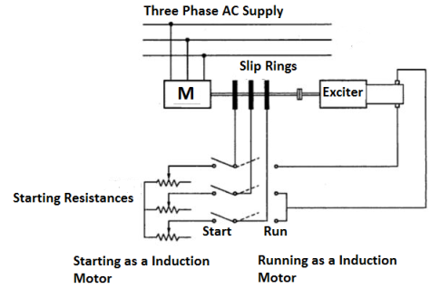
In the applications where high starting torque and constant speed are desired then synchronous induction motor can be used. It has the advantages of both synchronous motor and induction motor. The synchronous motor gives constant speed whereas induction motors can be started against full load torque.
Circuit Diagram
Working Principle-
Consider a normal slip ring induction motor having three phase winding on the rotor. The motor is connected to the exciter which gives D.C. Supply to the rotor through slip rings. One phase carries full D.C. Current while the other two carries half the full D.C. Current as they are connected in parallel. Due to this D.C. Excitation, permanent poles (N and S) formed on the rotor.
Initially it is run as a slip ring induction motor with the help of starting resistances. When the resistances are cut out the motor runs with a slip. Now the connections are changed and the exciter is connected in series with the rotor windings which will remain in the circuit permanently.
Advantages-
- The synchronous induction motor can start and synchronize against more than full load torque which is not possible with salient pole synchronous motor which must be started against light load.
- The exciter required for synchronous induction motor is of smaller capacity as the gap is not long as compared to normal salient pole motor.
- The rotor winding in synchronous induction motor can function as providing excitation and required damping. So, no separate damper winding is required.
- No separate starting and control equipment’s are required
Q13) A 1492 kW, unity power factor,3-phase, star-connected ,2300 V, 50 Hz, synchronous motor has a synchronous reactance of 1.95 ohm/phase. Compute the max. Torque in N-m which this motor can deliver if it is supplied from a constant frequency source and if the field excitation is constant at the value which would result in unity power factor at rated load. Assume that the motor is of cylindrical rotor type. Neglect all losses.
A13)
Rated kVA, 3-phase= S = 1492
Rated kVA per phase = 1492/3 = 497.333
Rated Voltage/phase = V =2300/√3 = 1327.906
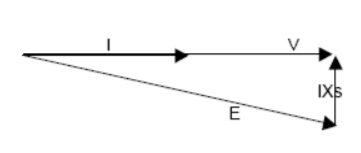


Max. Torque 
 Phase max.Torque=9855 Nm
Q14) Example: A factory takes 600 kVA at a lagging power factor of 0.6. A synchronous motor is to be installed to raise the power factor to 0.9 lagging when the motor is taking 200 kW. Calculate the corresponding apparent power (in kVA) taken by the motor and the power factor at which it operates.
A14)
Load power factor, Cos φ= 0.6
Sin φ = 0.8
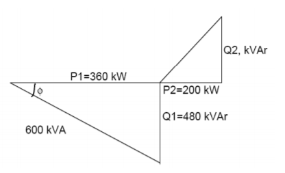
Load kVA = 600
P1, Load power = load kVA*cos φ = 360 kW
Q1, Load reactive power = kVA*Sin φ = 480 kVAr
P2, Motor power = 200 kW
Overall P.F., Cos α= 0.9 lag
Tan α = 0.484
Since, tan ∝ = (Q1-Q2)/P1+P2
𝑄2 = 𝑄1 − (𝑃1 + 𝑃2) tan ∝ = 208.78 KVAr
S2, Apparent power of the motor =  = 289.118 kVA
Motor P.F. =P2/S2= 0.692 lead
Q15) A 75-kW, 3 Y-connected, 50 Hz, 440-V cylindrical rotor synchronous motor operates at rated condition with 0.8 p.f leading. The motor efficiency excluding field and stator losses, is 95% and
  . Calculate (i) mechanical power developed (ii) armature current (iii) back e.m.f (iv) power angle and (v) maximum or pull-out torque of the motor.
A15)

(i) 
(ii) Since power input is known

(iii) Applied voltage/phase  . Let
. Let 
 as shown in fig.
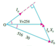
(iii)
Applied voltage/phase Let
Let  as shown in fig
(iv) ∴ 
(v) pull-out torque occurs when =90


Q16) A 3-ϕ, 150-kW, 2300-V, 50-Hz, 1000-rpm salient –pole synchronous motor has  and
and /Phase. Neglecting losses, calculate the torque developed by the motor if field excitation is so adjusted as to make the back e.m.f. Twice the applied voltage and =16°
A16)

Excitation power/phase=
Reluctance power/phase 
Total power developed 
Q17) A 3300-V. 1.5-MW, 3- , Y-connected synchronous motor has
  and
and  . Neglecting all loses, calculated the excitation e.m.f when motor supplies rated load at unity p.f. Calculate the maximum mechanical power which motor supplies rated field excitation.
A17)


 /Phase
If developed power has to achieve maximum value, then


Maximum 
Hence, maximum power developed for three phases=3×1070=3210 Kw
Q18) The input to an 11000-V, 3-phase, star-connected synchronous motor is 60A. The effective resistance and synchronous reactance per phase are respectively 1 ohm and 30ohm. Find (i) the power supplied to the motor (ii) mechanical power developed and (iii) induced emf for a power factor of 0.8 leading.
A18)
(i) Motor power input 
(ii) Stator Cu loss/phase  Cu loss for three phases


 stator impedance drop/phase
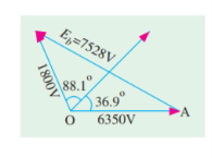
As seen from fig.


 line value of
Q19) A 500-V, I-phase synchronous motor gives a net output mechanical power of 7.46kw and operates at 0.9 p.f. Lagging. Its effective resistance is 0.8 If the iron and friction losses are 500 W and excitation losses are 800 W. Estimate the armature current. Calculate the commercial efficiency.
A19)
Motor input  Armature Cu loss
Power developed in armature is 


 iron and friction losses+excitation losses


Motor input=500×20.3×0.9=9090 W
 net input/input=7460/9090=0.8206 or 82.06%
Q20) A 2300-V, 3-phase, star-connected synchronous motor has a resistance of 0.2 ohm per phase and a synchronous reactance of 22 ohm per phase. The motor is operating at 0.5 power factor leading with a line current of 200 A. Determine the value of generated e.m.f per phase.
A20)
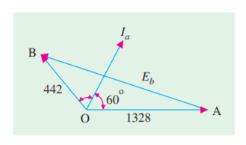
Here,


The vector diagram is shown in figure


Q21) A synchronous motor having 40% reactance and a negligible resistance is to be operated at rated load at(i) u.p.f (ii) 0.8 p.f lag(iii) 0.8 p.f lead. What are the values of induced e.m.f? Indicate assumptions made, if any.
A21)
Let  then reactance drop
(i) At unity p.f.


(ii) At p.f 0.8(lag)
Here  (b)
(b)
Alternatively,
(iii) At p.f. 0.8(lead.)
Here 

Again from Fig. 
Q22) A 2200-V. 3- , Y-connected, 50HZ, 8-pole synchronous motor has
  When the motor runs at no-load, the field excitation is adjusted so that E is made equal to V. When the motor is loaded, the rotor is retarded by
  mechanical.
Draw the phasor diagram and calculate the armature current, power factor and power of the motor. What is maximum power the motor can supply without falling out of step?
A22)
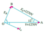
Per phase 


 ∆OAB
∆OAB
We get 


Total motor power input
Total Cu loss
Power developed by motor=168-2.34=165.66 Kw
