Unit - 6
Single Phase Induction Motor
Q1) Explain the working of single phase induction motor.
A1)
A single-phase induction motor consists of a single-phase winding mounted on the stator and a cage winding on the rotor. When a single-phase supply is connected to the stator winding a pulsating magnetic field is produced. Under these conditions, the rotor does not rotate due to inertia. Therefore, the single-phase induction motor is inherently not self-starting and requires some special starting means.
If, however, the single-phase stator winding is excited and the rotor of the motor is started by an auxiliary means, and the starting device is then removed, the motor continues to rotate in the direction in which it is started.
Consider two windings a, b so displaced that they produce magnetic fields 90° apart in space.
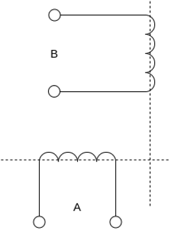
Suppose that these windings produce magnetic fields equal in magnitude and 90° apart in the time given by


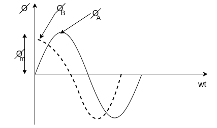
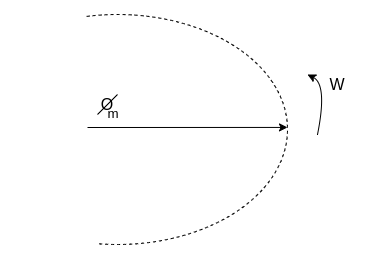
The resultant of these fields is the rotating magnetic field of constant magnitude  . This rotating magnetic field may be represented by a phasor constant magnitude
  .
.
Q2) Explain Double revolving field theory of single-phase induction motors.
A2)
Double revolving field theory of single-phase induction motors.
The double-revolving field theory of single-phase induction motors states that a stationary pulsating magnetic field can be resolved into two rotating magnetic fields, each of equal magnitude but rotating in opposite directions. The induction motor response to each magnetic field separately and the net torque in the motor is equal to the sum of the torques due to each of the two magnetic fields.
The equation for an alternating magnetic field whose axis is fixed in space is given by

Where  is the maximum value of the sinusoidally distributed air-gap flux density produced by a properly distributed stator winding carrying an alternating current of frequency
  is space displacement angle measured from the axis of the stator winding.


The first term on the RHS represents the equation of a revolving field moving in the positive  direction. It has a maximum value equal to
The second term on the RHS represents the equation of revolving field moving in negative  direction. It has a maximum value equal to
The field moving in the positive  direction is called the forward rotating field. The field moving in the negative
  direction is called a backward rotating field.
The positive direction is the direction in which the single-phase motor is started initially.
When the rotor is stationary, the induced voltages are equal and opposite consequently two torques are also equal and opposite. Hence, at standstill, the net torque is zero. In other words, a single-phase induction motor with a single stator winding inherently has no starting torque.
Q3) Explain with torque-speed characteristic rotor slip with respect to two rotating fields.
A3)
Rotor slip with respect to two rotating fields
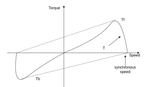
If the rotor is started by auxiliary means, it will develop torque and continue to run in the same direction as one of the fields. By definition, the direction in which the router is started initially will be called the forward field.
Let  = synchronous speed, n=rotor speed
The slip of the rotor with respect to the forward rotating field is

Since the backward rotating flux rotates opposite to the stator, the sign of n must be changed to obtain the backward slip.
Thus, the slip of the rotor with respect to the backward rotating field is


Adding 1 and 2


The first equation corresponds to a motor operation and the second equation denotes the braking region. Thus, the two torques have an opposite influence on the rotor.
The router equivalent circuits for the forward and backward rotating fluxes are shown below.
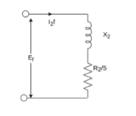
For forwarding rotating flux wave
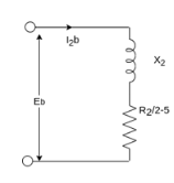
At stands still, the impedances are equal and therefore, the current  are equal. These currents produce mmfs which oppose the stator mmfs equally. Therefore, the rotating forward and backward flux is in the air gap are equal in magnitude and no torque is developed.
However, when the rotor rotates the impedance of the rotor circuits are unequal and the rotor current  is greater than the rotor current
Since the value of S is generally small (around 0.05)  is considerable higher than
  . Therefore,
  is greater than
  and forward flux is greater than the backward flux.
However resultant flux remains essentially constant. This resultant flux induces a voltage in the stator winding. Both flux waves induce voltages in the rotor and produce torque in the rotor. These two torques are in opposite directions. The net induced torque in the motor is equal to the difference between these torques.
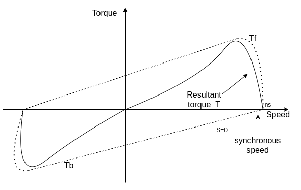
Q4) Draw and explain the equivalent circuit of single phase induction motor.
A4)
Equivalent circuit of Single Phase Induction Motor-
Most single-phase induction motors are two-phase motors in which the auxiliary winding is disconnected from the supply when the machine reaches a certain value. The machine then operates, as a true single-phase motor running on its main winding.
Consider the rotor is stationary and only the main winding is excited. The motor behaves like a single-phase transformer with its secondary short-circuited.
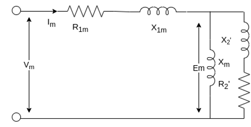
Where,
 = resistance of the main winding
 = leakage reactance of the main stator winding.
 = magnetizing reactance
 = stand Steel rotor resistance referred to the main stator winding.
 = standstill rotor leakage reactance refers to the main stator winding.
 = applied voltage
 = main winding current
The core loss branch is not shown, the core losses will be assumed to be lumped with the mechanical and stray losses as a part of the rotational losses of the motor.
According to the double-revolving field theory, the pulsating air gap flux in the motor at standstill can be resolved into two equal and opposite fluxes with the motor.
Thus, a single-phase induction motor may be considered as consisting of two motors having a common stator winding and two imaginary rotors, which rotate in opposite directions.
The standstill impedance of each rotor refers to the main stator is 
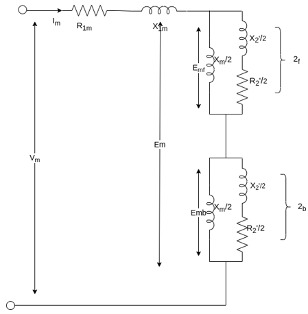
At standstill with the effects of forward & backward rotating fluxes. The first portion shows the effect of forwarding rotating flux, and the second portion shows the effect of backward rotating flux.

At standstill, 
Now suppose that the motor is started with the help of an auxiliary winding and the auxiliary winding is switched out after the motor gains its normal speed.
S=the slip of the rotor with respect to the forward rotating flux.
(2-S) =the slip of the rotor with respect to the backward rotating flux.
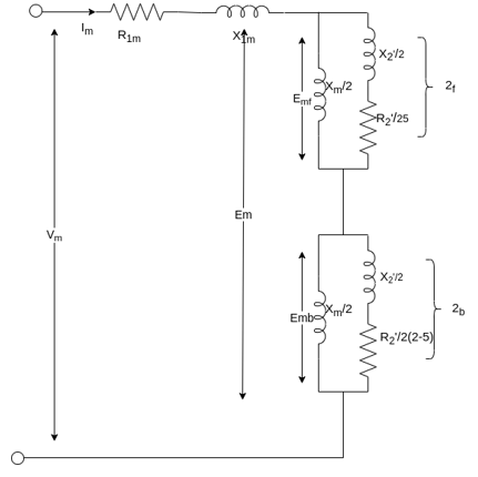
For simplification


Here  =rotor impedance offered to the forward field.
 =rotor impedance offered to the backward field.


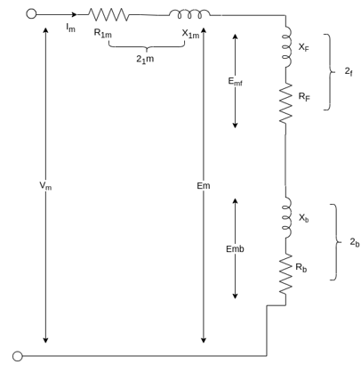
The current in stator winding is

Q5) A 230-volt 50 HZ, 4 pole single-phase induction motor has the following equivalent circuit impedances.

Friction windage and core loss =40W
For a slip of 0.03 pu, calculate
a) Input current
b) Power factor
c) Developed power
d) Output power
e) Efficiency
A5)


For the forward field circuit


For the backward field circuit


a) Input current 

b) Power factor=Cos (-60.95°) =0.4856 lagging
c) Developed power 

=479.65W
d) Output power=
=479.65-40=439.65 watt
Input power= 
=230×5.685×0.4856
=6349W
e) Efficiency=


Q6) A 230 volt 50 HZ, 4 pole single-phase induction motor has the following equivalent circuit parameters  Friction and windage, core losses are 50 Watt and slip is 0.025. Calculate
a) input current
b) power factor
c) developed power
d) output power
e) efficiency
A6)


For the forward field


For the backward field


a) Input current=

b) Power factor=cos (-66.0865)
=0.4053 lagging
c) Developed power 

=347.49 watt
d) Output power= 


Input power=VI


e) Efficiency= 

=56.17%
Q7) Explain in detail the block rotor test and no-load test on single phase induction motor.
A7)
Determination of equivalent circuit parameters-
The parameters of the equivalent circuit of a single-phase induction motor can be determined from the blocked rotor and no-load test. These tests are similar to those made on a three-phase induction motor. However, except for the capacitor run motor, these tests are performed with auxiliary winding kept open.
1. Blocked rotor test
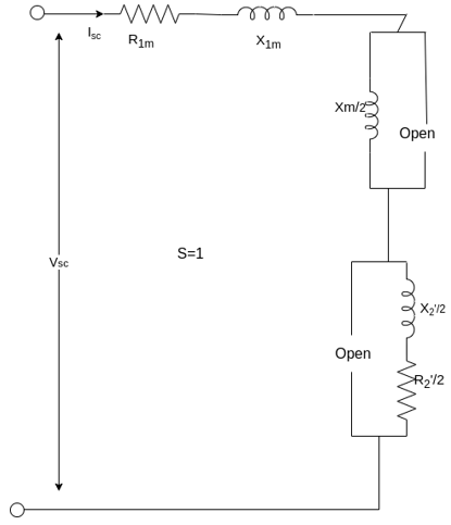
In this test, the router is at rest. Low voltage is applied to the stator so that rated current flows in the main winding. The voltage current and power input are measured. Let  denote the voltage, current, and power respectively under these conditions.
With the rotor blocked, S=1 the impedance  in the equivalent circuit is so large compared with
  that may be neglected from the equivalent circuit. Therefore, the equivalent circuit is shown below.
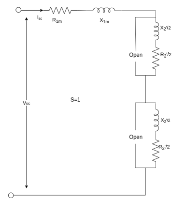
The equivalent impedance referred to the stator is given by


Since the resistance of the main stator winding  is already measured, the effective rotor resistance at LINE frequency is given by


The equivalent reactance  is given by

Since the leakage reactance  cannot be separated

Thus, from blocked rotor test the parameters  can be found if
  is known.
2. No-load test
The motor is run without load at rated voltage and rated frequency. The voltage current and input power are measured at no load, the slip S is very small close to zero and  is very large as compared to
The resistance  associated with the backward rotating field is so small as compared to
  that the backward magnetizing current is negligible.

Let  and
and  denote the voltage current and power respectively in the no-load test.

The no-load equivalent impedance is

The no-load equivalent reactance is

Q8) A 220V, single-phase induction motor gave the following test results.
Blocked rotor test: 120 V; 9.6 A, 460 W
No-load test: 220V, 4.6 A, 125 W
The stator winding resistance is 1.5 Ω and during the blocked rotor test, the starting winding is open. Determine the equivalent circuit parameters. Also find the core, friction, and windage losses.
A8)
- Blocked rotor test


2. No-load test


=0.1235


Q9) Compare single phase induction motor and three phase induction motor.
A9)
Single phase induction motors are constructed in fractional kilowatt capacity and are used in places where three phase supply is not readily available.
Sr. No | Single phase induction motor | Three phase induction motor |
1 | Single phase induction motor develops about 50% of the output of that of three phase Motors for the same size and temperature rise. | Output of three phase induction motor is more compare two single phase induction motor for the same size and temperature rise |
2 | Single phase induction motor has lower power factor | Better power factor |
3 | The starting torque is low in single phase induction motor | Starting torque is high, also maximum torque can be obtained at starting condition |
4 | Single phase Motors are costly than 3 phase Motors of the same rating | Less costly |
5 | They are generally available up to 1 kW rating. | They are available up to 50000 kW |
Q10) A three-phase, 12 pole, salient pole alternator is coupled to a diesel engine running at 500rpm. It supplies an induction motor which has a full load speed of 1440 rpm. Find the percentage slip and number of poles of the induction motor.
A10)
Frequency of supply to the induction motor f = pn/120 = 12 x 500 / 120 = 50 Hz
Speed of Induction motor = 1440 rpm
Number of poles of induction motor = p = 120 f / n = 120 x 50/1440 = 4.16
The number of poles are to be even
Selecting the nearest even number as the number of poles p = 4
Synchronous speed of the induction motor
Ns = 120f/p = 120 x 50 /4 = 1500 rpm
Slip = (Ns – N) / Ns = (1500 – 1440)/ 1500 = 0.04
Percentage slip = 4 %
Q11) A three phase, 50 Hz, 4 pole slip ring induction motor has a star connected rotor. The full load speed of the motor is 1460 rpm. The rotor resistance and stand still reactance per phase are 0.1 ohm and 1.5 ohm respectively. The open circuit voltage on open circuit between the slip rings is 90 volts. Determine (i) percentage slip (ii) induced emf in rotor per phase (iii) the rotor reactance per phase at full load (iv) the rotor current and full load power factor
A11)
(i) Ns = 120f/p = 120 x 50 /4 = 1500 rpm
Slip = (Ns – N) / Ns = (1500 – 1460)/ 1500 = 0.0266Percentage slip = 2.66 %
(ii) Induced emf per phase in rotor at stand still = 90/√3 =51.96 volts
Rotor induced emf at full load Er = sE2
= 0.0266 x 51.96 = 1.382 volts
(iii) rotor reactance at stand still = 1.5 Ω / phase
Rotor reactance per phase at full load = sX2
= 0.0399 Ω / phase
(iv) rotor impedance per phase at full load = Z2
= √ (R22+ sX22) = 0.1077 Ω
Rotor current per phase = 1.382/0.1077 = 12.83 amps
Full load power factor = R2/Z2
= 0.1/ 0.1077 = 0.929
Q12) If the induced emf in the stator of an 8-pole induction motor has a frequency of 50 Hz and that in the rotor is 1.5 Hz, at what speed is the motor running and what is the slip?
A12)
f = 50 Hz and fr = 1.5 Hz, Ns = 120f/p = 120 x 50/8 = 750 rpm
We have fr = sf
Hence s= fr /f = 1.5/50 = 0.03
Hence N = (1- s) Ns = (1- 0.03) x 750 = 727.5 rpm
Q13) The power input to a rotor of 440V, 50Hz, 6-pole, 3-phase, induction motor is 60kW. The rotor force is observed to make 80 alterations per minute. Calculate i) slip ii) rotor speed iii) rotor cu loss per phase?
A13) 80 alterations per minute=80/60 cycles per second=1.333Hz=sf
i)slip=1.333/50=0.027 P.u.=2.7%
Ii)Rotor speed N=(1-s) Ns= (1-0.027) x 1000=973.33rpm
Ns=120f/P=120 x 50/6=1000rpm
Iii)rotor cu loss/phase= =
= =0.54kW
Q14) The power input to a 3-phase induction motor is 80kW. The stator loss is total 1kW. Find the mechanical power developed and the rotor cu loss per phase if the slip is 3%?
A14)
P2= stator input – stator losses=80-1=79kW
Pm=(1-s) P2== (1-0.03) x 79=76.63kW
Total rotor cu loss=sP2=0.03 x 79=2.37kW
Rotor cu loss per phase=2.37x1000/3=790W
Q15) The power input to a rotor of a 400V, 50hz,6-pole, 3-phaseinduction motor is 15kW. The slip is 4%. Calculate i) frequency of rotor current. i)rotor speed. Iii)rotor cu loss iv) rotor resistance/phase if rotor current is 50A?
A15)
i) frequency of rotor current=sf=0.04 x 50=2Hz
Ii) Rotor speed N=(1-s) Ns= (1-0.04) x 1000=960rpm
Ns=120f/P=120 x 50/6=1000rpm
Iii) rotor cu loss=s x rotor input=0.04 x 15=0.6kW
Iv)rotor cu loss/phase=0.6 x 1000/3=200W
602R2=200
R2=0.055Ω
Q16) A 110V, 3-phase star connected induction motor takes 25A at a line voltage of 30V with rotor locked. With this line voltage power input to motor is 400W and core loss is 30 W. The dc resistance between the pair of stator terminals is 0.1 ohm. If ratio of ac to dc resistance is 1.6. Find equivalent leakage reactance per phase and stator and rotor resistance per phase?
A16)
S.C voltage/phase= 30/ =17.3V
Is=25A/phase
Z01=17.3/25=0.7ohm/phase
Stator and cu loss=400-30=370W
3 x 252xR01=370
R01=0.197ohm
Leakage reactance/phase X01= =
= =0.67ohm
Dc resistance/phase stator=0.1/2=0.05ohm
Ac resistance/phase R1=0.05x1.6=0.08ohm
Effective resistance/phase rotor referred to stator  =0.197-0.08=0.117ohm
Q17) In a no load test an induction motor took 8A and 440W with a line voltage of 110V. If the stator resistance/phase is 0.05ohm and frictional and windage losses are 135W. Calculate the exciting conductance and susceptance/phase?
A17)
Stator cu loss=3 R1=3x82x0.05=9.6W
Stator core loss=440-135-9.6=295.4W
Voltage/phase v=110/ V
V
Core loss=3G0V2
295.4=3 G0(110/ )2
)2
G0=0.024siemens/phase
Y0=I0/V= (8// /110=0.042siemens/phase
B0= =0.034siemens/phase