Unit 4
Electrical Circuit Analysis using Laplace transform
Q1) Explain Laplace transform?
A1)
Consider an LTI system by a complex exponential signal of the form
x(t) = Gest.
Where s = any complex number = σ+jω
σ = real of s, and
ω = imaginary of s
The response of LTI can be obtained by the convolution of input with its impulse response i.e.
y(t)=x(t)×h(t)=
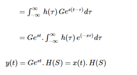
Where H(S) = Laplace transform of 
Similarly, Laplace transform of 
Q2) Explain the analysis of electrical circuit for different function?
A2)
For unit step function:
u(t) = 0 t<0
1 t>0
L {u(t)} = F(s) =  -st dt = 1/s
For impulse function
∂(t) = { 0 t
1 t=0 }
L [∂(t)] = F(s) =  e-st dt = 1
Unit ramp function:
r (t) = 0 t ≤ 0
t t≥ 0
L { t u(t) } =  e-st dt = t (-1/s e -st ) | 0 ∞ -
  e-st dt
= 0 + 1/s  e-st dt
= 1/s (-1/s e -st ) | 0 ∞
= 1/ s 2
Exponential function:
f(t) = e-at u(t) where a > 0 and u(t) is the unit step function
F(s) =  dt
dt
F(s) =  at e -st dt
- e – (s+a) t / s + a | t=0 t=∞ = 1/ s + a
Sinusoidal function
L { sin(wt)} =  jwt – e – jwt / 2j . e -st dt
= 1/2j [ 1/ s – jw – 1/ s + jw ] = w/ s2 + w2
Cosine function
L [ coswt] =  jwt + e – jwt / 2 . e -st dt
= ½ [ 1/s-jw – 1/ s+jw] = s/ s2 + w 2
Q3) Find the Laplace transform of x(t):

A3)

x(t) = x1 (t) + x2(t) = u(t-2) – u(t-4)
L{x(t)} = X(s) = 1/s e -2s – 1/s e -4s
X(s) = 1/s ( e -2s – e -4s)
Q4) Find the convolution integral?
A4)
Consider LTI system which is initially relaxed at t=0. If the input to the system is impulse then the output of the system is denoted by h(t) and is called the impulse response of the system.
h(t) = T|∂ (t)|-------------------(1)
We know that any arbitrary signal x(t) can be represented as
x(t) =  (
(
 (t-
(t- dτ ----------------------------------------(2)
The system output is given by
y(t) = T[x(t)] ----------------------------------------------------------------------(3)
Substituting (2) in (3) we get
y(t) = T [  ∂(t-
∂(t- dτ -----------------------------------------------(4)
For linear system
y(t) =  ∂(t-
∂(t- dτ --------------------------------(5)
If the response of the system due to impulse ∂(t) is h(t) then the response of the system due to delayed impulse is
h(t,τ) = T [ (t -τ) d τ -------------------------------------------------------(6)
y(t) =  h(t,
h(t, dτ -------------------------------------------------------------------(7)
For a time invariant system the output due to delayed input by T is equal to delayed output by T that is
h(t,τ) = h(t-τ) ---------------------------------------------------------(8)
Hence,
y(t) =  h(t-
h(t- dτ -----------------------------------------(9)
This is called convolution integral or convolution. The signal x(t) and h(t) can be represented as
y(t) = x(t) * h(t)
Q5) Find the convolution of x1(t) = e -at u(t) and x2(t) = e -bt u(t)
A5)
x1(t) * x2(t) =  x2(t-
x2(t- dτ
dτ
A signal x(t) is said to be casual if x(t) =0 for t<0
In this case both the signals x1(t) and x2(t) are casual.
x 1(t) * x 2(t) =  x2(t-
x2(t- dτ
dτ
=  e -at e -b (t-τ) dτ
= e -bt  e –(a-b)τ dτ
= e -bt [ e –(a-b)t -1]/ b-a for t≥ 0
= e -at – e -bt / b-a u(t)
Q6) Find the inverse Laplace transform?
A6)
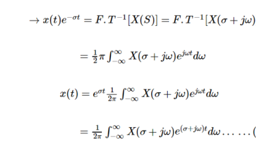
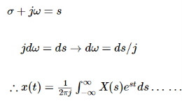
We know that
X(s) = F.T [ x(t) e –  t ]
t ]
 -------------------------------(1)
 (2)
(2)
Q7) Explain the transformed network with initial conditions?
A7)
If v(t) and i( t) are the voltage across and the current through an inductor of L henries, then
v(t) = L di/dt -----------------------------(1)
The Laplace transform of this equation (assuming zero initial current) is
V(s) = L s I(s) -------------------------------------(2)
Similarly, for a capacitor of C farads, the voltage-current relationship is
i(t) = C dv/dt
And its Laplace transform, assuming zero initial capacitor voltage, yields
I(s) = C s V(s) that is
V(s) = 1/ Cs I(s)
For a resistor of R ohms, the voltage-current relationship is
v(t) = R i(t) and its Laplace transform is
V(s) = R I(s)
Thus, in the "frequency domain," the voltage-current relationships of an inductor and a capacitor are algebraic; these elements behave like resistors of "resistance" Ls and 1/ Cs, respectively.
Resistor :
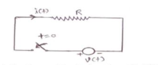
The current voltage relation for resistor is given by : v(t) = i(t) * R
From the above relation it can be said that the instantaneous value of current depends on the instanteneous value of voltage and vice vera.
The past values of current or volatge does not affect present value of current or voltage that is the behaviour of resistance remains same irrespective of past value of current and voltage.
Inductor :
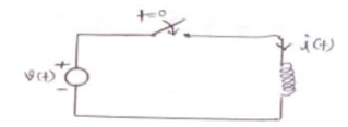
When the switch is closed at t=0 and current throgh an inductor cannot change instantaneously. As a result closing a switch to connect to inductor to a source of energy will not cause current to flow at that instant and the inductor will act as an open circuit.
The current through the inductor is given by
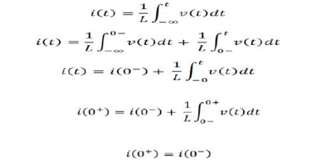
Hence current at 0+ is equal to current at 0-. So if i(0-)=0 then i(0+) =0 also. Hence, it acts as open switch.

If current Io amps flows in the inductor at the instant of switching takes place that current will continue to flow and for the initial instant the (t=0+) inductor can be considered as current source Io amps.

Capacitor:
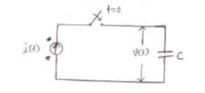
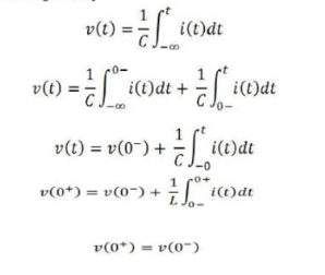
The voltage across capacitor is given by
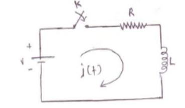
Q8) In the network shown below if at t=0 switch ‘K’ is closed, Find the values of i, di/dt and d 2 i/ d t 2 at t=0+. Assume V =100V , R=1000Ω and L =1H.
A8)
Before the switch is closed i(0-)=0
Draw the circuit immediately after switching, Inductor acts as open . Since the inductor will not allow the current to change instantaneously. Hence i(0+) =0
Draw the general network after switching and write KVL
V = Ri + L di/dt
Obtain the expression for first derivative di/dt = (V -R(i))/L substituting the values we get
Di/dt =100 A/s
Obtain the expression for second derivative d2 i(0+)/ dt 2 = R/L di/dt
Substituting the known values we get
d 2 i(0+)/ dt 2 = -100000 A/s2
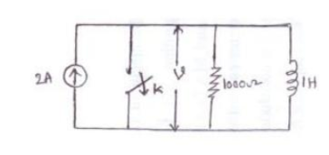
Q9) In the circuit shown switch ‘k’ is opened at t=0. Find the values of v, dv/dt ,
d 2 v / d t 2 at t=0+
A9)
At t=0-
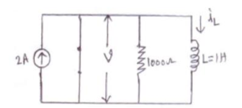
v(0-) =0 , iL(0-) =0 since current through the inductor cannot change suddenly.
At t=0+
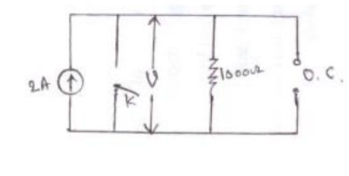
v(0+) = i x R = 2 x 1000 = 2000V
Apply KCL to the given circuit at t=0+ we get
v/R + (1/L)  = 2 -------------------------------------------(1)
Differentiate equation (1) with respect to t we get
(1/R) dv/dt + (1/L) v =0
At t=0+ the equation becomes
(1/R) dv(0+)/dt + (1/L) v (0+)=0
Dv(0+)/dt = -R/L v(0+)
= (-1000/1) x 2000
= -2 x 10 6 V/S
Q10) Find the transfer function for the circuit
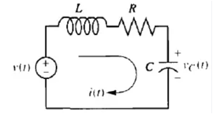
A10)
The capacitor voltage is treated as the output and the applied voltage as the input. Summing the voltages around the loop and assuming zero initial conditions yields the integro-differential equation for the network as
L di(t)/dt + R i(t) + 1/C  d
d  = v(t)
Changing variables from current to charge using i(t) = d q(t)/dt yields
L d 2 q(t)/ dt2 + R dq(t)/dt + 1/C q(t) = v(t)
From the table q(t) = C v(t)
LC d2 vc(t)/ dt 2 + RC d vc(t)/dt + vc(t) = v(t)
Taking Laplace transform and assuming initial conditions to be zero
( LC s2 + RC s +1) Vc(s) =V(s)
Hence,
Vc(s) / V(s) = 1/LC / s2 + R/L s + 1/LC
The Laplace transform
For capacitor
V(s) = 1/Cs I(s)
For resistor
V(s) = R I(s)
For inductor
V(s) = Ls I(s)
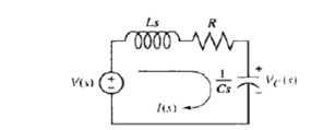
Laplace transformed network
L di(t)/dt + R i(t) + 1/C  = v(t)
Assuming zero initial conditions
(Ls + R + 1/Cs) I(s) = V(s)
I(s) / V(s) = 1/ Ls + R + 1/sC
But the voltage across the capacitor Vq(s) is the product of current and impedance of the capacitor. Thus,
Vc(s) = I(s) / Cs
I(s) = Cs * Vc(s)
Therefore
Vc(s) *Cs/ V(s) = 1/ Ls +R+1/Cs
Vc(s) /V(s) = 1/ Cs(Ls +R+1/Cs)
= 1/ LC s2 + CRs + Cs/Cs
= 1/LC s2 + CRs +1
= 1/LC / s2 + R/L s + 1/LC
Vc(s) / V(s) = (1/LC) / s 2 + R/L s + 1/LC
Q11) Explain poles and zeros?
A11)
All poles and zeros of Network function have the form of ratio of two polynomials in s as
G(s) = P(s)/ Q(s)
P(s) is the numerator polynomial in s having degree m while Q(s) is the denominator polynomial having degree n. Hence network function can be expressed as,

Now the equation P(s) =0 has m roots while equation Q(s) has n roots. Thus G(s) can be expressed in the factorized form as

Where z1,z2…….zm are the roots of the equation P(s) =0 and P1,P2……Pn are the roots of the equation Q(s) =0.
K = a0/b0 = scale factor
Thus z1,z2…….zm,P1,P2…….Pn are the values of s and hence are complex frequencies as s variable is a complex variable.
Poles:
The values of ‘s’ that is complex frequencies which make the network function infinite when substituted in the denominator of a network are called poles of the network function.
s = p1,p2……..pn are the poles of G(s)
If such poles are real and non -repeated these are simple poles/ If a particular pole has same value twice or more than it is repeated pole. A pair of poles with complex conjugate values is called pair of complex conjugate poles.
The poles are the roots of the equation by equating denominator polynomial of the network function to zero. Such equation is called the characteristic equation of the network.
Zeros:
The value s that is complex frequencies make the network function zero when substituted in the numerator of network function called zeros of the network function.
s = z1,z2………..zm are the zeros of G(s)
The zeros are the roots of the equation by equation numerator polynomial of a system function to zero.
When the order m > n there are m-n poles at infinity while m<n then n=m is zeros at infinity. Hence for an9y rational network function poles and zeros at infinity and zero are taken into consideration in addition to finite poles and zeros . The total number of zeros is equal to the number of poles.