Unit 6
Time Varying Fields and Maxwell’s Equations
Q1) Explain Faraday’s law of Electromagnetic induction?
A2)
According to Faraday’s experiment a static magnetic field cannot produce any current flow. But with time varying field emf induces which may drive a current in a closed path or circuit. This emf is nothing but a voltage that induces from changing magnetic fields or motion of the conductors in a magnetic field or motion of the conductors in a magnetic field. Faraday discovered that the induced emf is equal to the time rate of change of magnetic flux linking with the closed circuit.
e = -N dɸ/dt volts. ---------------------------(1)
Where N = numbers of turns in the circuit
e = Induced emf.
Let us assume single turn circuit i.e N=1 then Faraday’s law can be stated as
e = - dɸ/dt volts --------------------------(2)
The minus sign in equations(1) and (2) indicate that the direction of the induced emf is such that to produce current which will produce a magnetic field to oppose the orginal field.
Let us consdier Faraday’s law. The induced emf is a scalar quantity measured in volts. Thus the induced emf is given by
e =  . d
. d  --------------------------------------------(3)
The induced emf in eq(3) indicates a voltage about a closed path such that if any part is changed the emf will aslo charge.
The magnetic flux ɸ passing through a specified area is given by
ɸ=  . d
. d  where B = magnetic flux density
Eq(2) can be rewritten as
e = -d/dt  . d
. d  -------------------------------------------------------------------(4)
From (3) and (4) we get
e =  . d
. d  = -d/dt
  . d
. d  --------------------------------------------------(5)
Q2) Explain displacement current ?
A2)

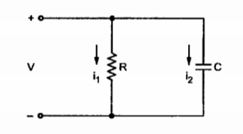
Consider a parallel circuit consisting of resistor and capacitor driven by a time varying volatge V as shwn in figure.
Let the current flowing through resistor R be i1 and the current flowing through capacitor C be i2. The nature of current through the resistor R is different than that flowing through the capacitor. The current through the resistor is due to the actual motion of charges. Thus the current through resistor is written as
i 1 = V/R
This current is called conduction current as the current is flowing because of actual motion of charges denoted by ic.
Let A be the cross sectional area of resistor then the conduction current density is given by
 = ic/A =

Asssume that the intial charge on a capacitor is zero. Then for time varying volatge applied across parallel plate capaciotr the current through the capacitor is given by
i 2 = C dv/dt
Let the two plates of area A be seperated by distance d with dielectric having permittivity  between the plates. Then
i 2 =  /d dv/dt
This current is called displacement current denoted by iD.
Q3) Explain electrical field?
A3)
The electric field produced by the volatge applied between the two plates is given by
E = V/d
Or V = (d) ( E )
Substituting V we get
iD = i 2 =  /dx d/dt (d E)
iD =  /d x dx (d E) /dt
iD =  . (d E) /dt
Q4) Explain integral form of Maxwell’s equations?
A4)
According to Ampere’s circuit law the line integral of a magnetic field intensity  around a closed path is equal to the current enclosed by the path.
 . d
. d  = I enclosed
Replacing current by the surface of conduction of current density  over an area bounded by the path of integration of
  we get
 . d
. d  =
=  . d
. d 
The above equation can be further made general by adding displacement current density to conduction current density as follows
 . d
. d  =
=  +
+  /
/  d
d 
This equation is in integral form.
Q5) Explain point form of Maxwell’s equation?
A5)
Applying Stroke’s theorem to LHS of the equation we get
 x
x  d
d  =
=  +
+  /
/  d
d 
Assuming that the surface considered for both the integrations is same we can write
 x
x  =
=  +
+  /
/  d
d 
This is expressed in point form.
Q6) Explain motional electromotive force?
A6)
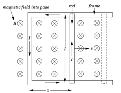
Consider a simple circuit in which a conducting rod of length  slides along a U-shaped conducting frame in the presence of a uniform magnetic field. This circuit is illustrated in Figure.

Suppose that the magnetic field is directly perpendicular to the plane of the circuit. Suppose we move the rod to the right with the constant velocity  . The magnetic flux linked by the circuit is simply the product of the perpendicular magnetic field-strength,
  , and the area of the circuit,
  , where
  determines the position of the sliding rod. Thus,

|
Now, the rod moves a distance  in a time interval
  , so in the same time interval the magnetic flux linking the circuit increases by
 |
|
It follows, from Faraday's law, that the magnitude of the emf  generated around the circuit is given by
 Thus, the emf generated in the circuit by the moving rod is simply the product of the magnetic field-strength, the length of the rod, and the velocity of the rod. If the magnetic field is not perpendicular to the circuit, but instead subtends an angle 
Where  |
Q7) Explain the boundary conditions?
A7)
The Maxwell’s equations are useful in determining the conditions at the boundary surface of the two different media. Consider the boundary between medium 1 with parameters  1, μ1 and
  and medium 2 with parameters
  , μ2 and
  .
.
In general the boundary conditions for time varying fields are same as those for static fields. Thus at the boundary refering boundary conditions for static electric magnetic fields we write
The tangential component of electric field intensity  is continuous at the surface
E tan 1 = E tan 2
The tangentail component of the magnetic field intensity is continuos across the surface except for perfect conductor.
H tan1 = H tan2
At the surface of perfect conductor the tangential componenet of magnetic field intensity is discontinuous at the boundary
H tan1 – H tan2 = K
The normal component of the elctric flux denity is continuous at the boundary
BN1 = BN2
- Two long parallel conductors are separated by 2cm in air carrying current of 100 ampere flowing in opposite direction. Find the force per meter length of the conductor.
Solution:
I1= I2 = 100A
d = Distance of separation = 2cm = 2 x 10 -2 m
μ= μoμr = μo for air μr=1
The force per meter length between two long current carrying conductors is given by
F/L = μ I1 I2 / 2πd
= 4 π x 10 -7 x (100) 2 / 2π x 2 x 10 -2
= 0.1 N/m
As the currents in parallel conductors are flowing in opposite direction the force will be force of repulsion.
2. Two wires carrying current in the same direction of 3A and 6A are placed with their axes 5cm apart , free space permeability = 4π x 10 -7 H/m. Calculate the force between them in kg/m length.
Force between two parallel conductors is given by
F = μ I1 I2 l / 2πd
Force per unit meter length is given by
F/l = μ . I1 . I2 / 2 π.d = μo μr I1 I2 / 2πd
For free space μr=1
F/l = 4π x 10 -7 x 3x6/ 2π x 5 x 10 -2
F/l = 72 μ N/m
The force expressed in kg/m is given by
F/l = 72 x 10 -6 / 9.8 = 7.3469 x 10 -6 kg/m
3. A magnetic field  = 3.5 x 10 -2
  exerts a force on a 0.3 m long conductor along x-axis . If a current of 5A flows in -
  direction determine what force must be applied to hold conductor in position.
The force exerted on a straight conductor is given by
 = I
= I  .
.
= 5(-0.3  ) x ( 3.5 x 10 -2
  )
)
= -0.0525 (- )
)
= - 0.525 (- 
= 0.0525  N
N
Hence the force applied to hold the conductor in position must be
 = -0.0525
  N
N
