UNIT 5
FREE BODY DIAGRAM
Q1) Two identical spheres having weight 1000 N are kept in a container as shown in figure. Find the reaction at all contact surfaces.
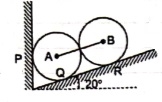
 A1)
A1)
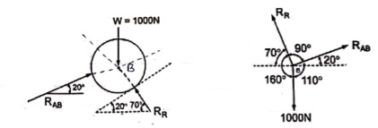
 Consider the free body diagram of sphere B as shown below:
By lami’s theorem


 RRR = 939.69 N

 = RAB
= RAB
Now consider FBD of sphere A
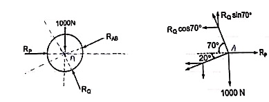
∑Fx = 0
-RB cos 20 – RQ cos 70 + Rp = 0
-342.02 cos 20 – RQ sin 70 + Rp = 0
 Rp = 321.39 + 0.34 RQ ----------------(1)
∑ fy = 0
RQ sin 70 – 342.02 sin 20 – 1000 = 0
 RQ = 1188.66 N - put in equation (1)
 Rp = 725.5 N
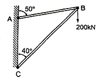
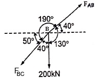
Q2) two members AB & BC are supporting a load of 200 kN as shown in figure. Find the forces developed in the members AB & BC
 A2)
A2)
 Consider the free body diagram of joint B as shown in figure
Assume that member BC is in compression & AB is in tension. By using Lami’s theorem at B,


 FAB = -740.33 kN
-ve sign indicates that member AB is not in Tension but is in compression.
Now,


-ve sign indicates that member BC is not in compression but in tension.
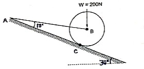
Q3) A Sphere of weight 200 N rests on a smooth inclined plane. A sphere is kept in equilibrium by means of cable as shown. Find tension in cable and reaction.
A3)
 Consider the FBD of sphere B as shown in figure above.
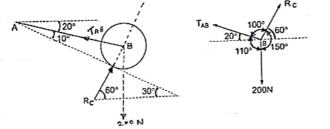
Applying lami’s theorem, we have


 RC = 190.84 N


 TAB = 101.54 N
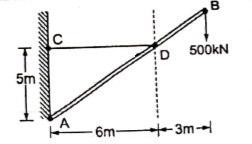
Q4) The bar AB supports a load of 500 kN as shown in figure. The bae is kept in equilibrium by means of horizontal rope. Find tension in rope and reaction at A,
A4)
 Consider the FBD as shown
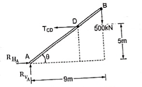
Applying conditions of equilibrium,
∑fx = 0
RHA – TCD = 0
RHA = TCD ------- (1)
∑fy = 0
RVA – 500 = 0
 RVA = 500 kN
Taking moment about point A,
∑MA = 0
-(TCD × 5 ) + (500 × 9) = 0
-TCD × 5 = -4500
TCD = 
 TCD = 900 kN
Putting the value in equation (1)
RHA = TCD
RHA = 900 kN
Q5) Find the axial force in the bar AB & AC as shown in figure.
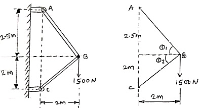
 Consider the free body diagram of all forces at B.
A5)
Q1 = tan -1  = 51.34º
Q2 = tan-1  = 45º
= 45º
Let the forces developed in the member AB & AC are FAB &FBCrespectively. The force diagram will be as follows at B.
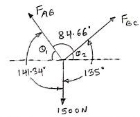
Applying Lami’s Theorem:


 FAB = 1067.19 N

FBC = 942.81 N
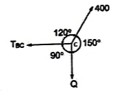 Q6) Find the tensions in the string AB, BC, CD, DE of the given system as shown in figure. String BC is horizontal & pulley D is frictionless.
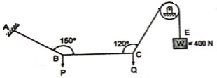
A6)
 The string passes over the pulley & is attached to weight w = 400 N.
Thus TCD = TDE = 400 N
Consider joint C & apply Lami’s theorem


Now consider FBD at joint B
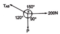
By using Lami’s theorem


TAB = 230.94 N

Q6) The 200-kg crate in Fig. Below is suspended using the ropes AB and AC. Each rope can withstand a maximum force of 10 kN before it breaks. If AB always remains horizontal, determine the smallest angle to which the crate can be suspended before one of the ropes breaks.
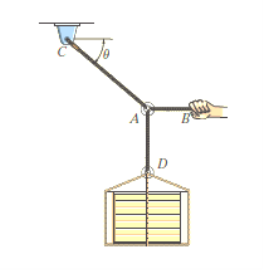
A7)
Free-Body Diagram: We will initially understand the equilibrium of ring. There are three forces acting on it, as shown in fig. (b). The magnitude of is equal to the weight of the crate, i.e.,
FD = 200 (9.81) N = 1962 N < 10 kN
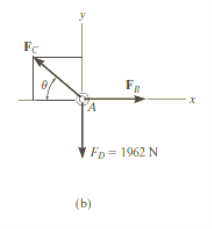
Equations of Equilibrium: Applying the equations of equilibrium along the x and y axes,
Σ Fx = 0
i.e. - FC cos θ + FB = 0
Therefore FC = ( FB / cos θ )
Σ Fy = 0
i.e. FC sin θ - 1962 N = 0
As seen from the above equations, FC is always greater than FB as cos θ is less than or equal to 1. So, rope AC will reach the max value of tensile force of 10 kN before that of rope AB. Thus, substituting FC = 10 kN in the above equations, we get
[10(103) N] sin θ - 1962 N = 0
Thus, θ = 11.30
The force developed in rope AB can be obtained by substituting the values for θ and FC into Equations mentioned above.
We get, FB = 9.81 kN.
In this way, using equations of equilibrium and free-body diagrams, we can calculate unknown quantities of the given problem.
Q7) Explain Kinematic Constraints Between Two Rigid Bodies?
A8)
The transformation matrix above is a specific example for two unconstrained rigid bodies. The transformation matrix depends on the relative position of the two rigid bodies. If we connect two rigid bodies with a kinematic constraint, their degrees of freedom will be decreased. In other words, their relative motion will be specified in some extent.
Suppose we constrain the two rigid bodies above with a revolute pair as shown in Figure
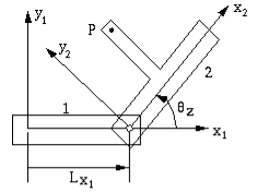
Figure Relative position of points on constrained bodies
The difference is that the Lx1 is a constant now, because the revolute pair fixes the origin of coordinate system x2y2z2 with respect to coordinate system x1y1z1. However, the rotation  z is still a variable. Therefore, kinematic constraints specify the transformation matrix to some extent.
Q8) Calculate the degrees of freedom of the mechanisms shown in Figure.
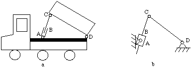
Figure Dump truck
A9)
n = 4, l = 4 (at A, B, C, D), h = 0

Q9) Calculate the degrees of freedom of the mechanisms shown in Figure.
A10)
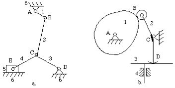
Figure Degrees of freedom calculation
For the mechanism in Figure 4-15a
n = 6, l = 7, h = 0

For the mechanism in Figure 4-15b
n = 4, l = 3, h = 2

Q10) Difference Between Kinetics and Kinematics?
A11)
| |
Kinetics | Kinematics |
Deals with the causes for the motions of the object | Deals with the position, acceleration, speed of an object |
Takes into consideration the mass of the object | Doesn’t take into consideration the mass of the object |
Its practical applications can be found in the designing of automobiles | Its application can be found in the study of the movement of celestial bodies |
It takes forces explicitly into account | It doesn’t take forces explicitly into account |
It does not have more mathematical expressions | It has more mathematical expressions |
It is also known as dynamics | It is called with the same name |
This topic is used in various branches of science such as biology, chemistry and physics | This topic is used in physics, mechanics in terms of engineering |