UNIT 7
BENDING MOMENT
Q1) Draw Shear Force and Bending Moment Diagrams for a Simply-Supported Beam under a Uniform Load
A1)
Shear force is the force in the beam acting perpendicular to its longitudinal (x) axis. For design purposes, the beam's ability to resist shear force is more important than its ability to resist an axial force. Axial force is the force in the beam acting parallel to the longitudinal axis.
The following is a drawing of a simply-supported beam of length L under a uniform load, q:

This beam has the following support reactions:
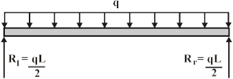
Where Rl and Rr are the reactions at the left and right ends of the beam, respectively.
The shear forces at the ends of the beam are equal to the vertical forces of the support reactions. The shear force F(x) at any other point x on the beam can be found by using the following equation.

Where x is the distance from the left end of the beam.
Shear force diagrams are simply plots of the shear force (on the y-axis) versus the position of various points along the beam (on the x-axis). Thus, the following is the generalized shear force diagram for the beam shown above.
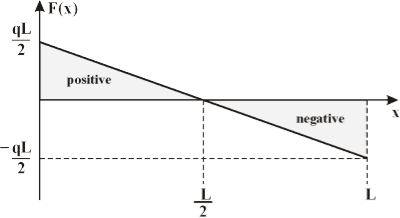
The bending moment at any point along the beam is equal to the area under the shear force diagram up to that point. (Note: For a simply-supported beam, the bending moment at the ends will always be equal to zero.)
To calculate the bending moment the beam must be broken up into two sections:
(a) | One from x = 0 to x = L/2 and |
(b) | The other from x = L/2 to x = L. |
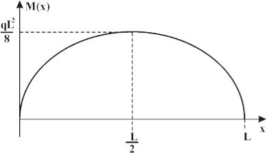
The bending moment M(x) at any point x along the beam can be found by using the following equations:

Bending moment diagrams are simply plots of the bending moment (on the y-axis) versus the position of various points along the beam (on the x-axis). Thus, the following is the generalized bending moment diagram for the beam shown above.
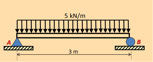
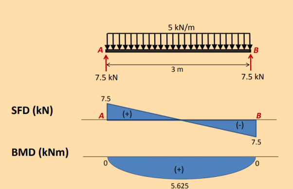
Q2) Calculate the shear force and bending moment for the beam subjected to an uniformly distributed load as shown in the figure, then draw the shear force diagram (SFD) and bending moment diagram (BMD).
A2)
By taking the moment at A:
ΣMA = 0
– RBy × 3 + 5 × 3 × 3/2 = 0
RBy = 7.5 kN
ΣFy = 0
RAy + RBy = 5 × 3
RAy = 15 – 7.5
RAy = 7.5 kN
ΣFx = 0
RAx = 0
These results for V and M can be checked by noting that dV/dx = w. This is correct, since positive w acts downward. Also, notice that dM/dx = V. The maximum moments occurs when dM/dx = V = 0.
Ma-a = 0,
–M + 7.5x – 5x (x/2) = 0
M = 7.5x – 5x 2 /2
M = maximum when 0
DM / dx 7.5 5x 0
x = 1.5 m
Therefore, Mmax = 5.625 kNm
Q3) Explain the different kind of beams?
A3) The following are the Important types of beam
Types of Beam
1. Cantilever beam,
2. Simply supported beam,
3. Overhanging beam,
4. Fixed beams, and
5. Continuous beam.
1. Cantilever beam
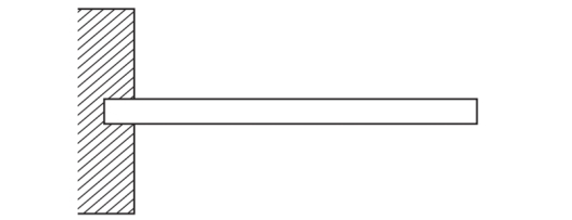
A beam which is fixed at one end and free at the other end, is known as cantilever beam. Such beam is shown in Fig.
Cantilever beam
2. Simply Supported beam
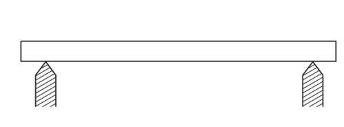
A beam supported or resting freely on the supports at its both ends, is known as simply supported beam. Such beam is shown in Fig.
Simply Supported beam
3. Overhanging Beam
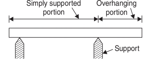
If the end portion of a beam is extended beyond the support, such beam is known as overhanging beam. Overhanging beam is shown in Fig.
Over Hanging beam
4. Fixed Beam
A beam whose both ends are fixed or built-in walls, is known as fixed beam. Such beam is shown in Fig. A fixed beam is also known as a built-in or encastred beam.
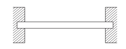
Fixed beam
Continuous Beam
A beam which is provided more than two supports as shown in Fig. Is known as continuous beam.
 Continuous beam
Q4) Analyse beams loadings?
A4)
Beam diagrams are used as a fundamental way to teach engineers the basic of static loading. Beams are structural elements that are able to withstand load by its resistance to bending. The bending force can be a result of external loads, weight, or the length of the beam. The beams experience a bending moment and a shear moment due to these loads.
Beams are classified based on their supports. Besides truss-supported beams, beams are classified in the following groups:
• Simply supported: A beam supported on the ends, which are free to rotate and have no moment resistance.
• Fixed: A beam supported on both ends, which are fixed in place.
• Overhanging: A simple beam extending beyond its support on one end.
• Double overhanging: A simple beam with both ends extending beyond its supports.
• Continuous: A beam extending over more than two supports.
• Cantilever: A projecting beam fixed only at one end, while the other end has no support.
Below we will analyse some classic loading examples of these beam categories.
Cantilever Beam:
- This type of beam has one end fixed and other end free.
- Fixed end will have Vertical reaction and Moment and Zero deflection.
- Free end will have deflection only.
Overhanging Beam:
There are Two types of overhanging beams.
- Single overhanging Beam
- Double overhanging Beam
Single Overhanging Beam:
- It has two supports, hinged at one end, roller at other end. Overhanging portion at any one of the supports.
- Loads can be applied on overhanging portion and can be converted to equivalent moment at the support.
- Moment and Reactions are same as that of Simply Supported Beam.
Double Overhanging Beam:
- This type of Beams will have over hangs at both the support.
- Both the Overhanging beams will have rotation at supports.
Q5) Explain stress strain in beams?
A5) Stresses and Strains in Beams
Given the loads and moments at each cross section, we can calculate the stress and strain at each location.
Consider the bending of a slender beam (one for which the cross section is much smaller than the length). A moment acting on the beam causes a deformation called flexure. Let the radius of the osculating circle of the beam be ρ. Consider an elemental length ds in the neutral plane (for which the deformation is zero). This element subtends an angle θ at the center of curvature, so that
Ds /dθ = ρ
If we move a distance y along the radius, we have the length of the arc subtended would be (ρ − y) dθ. Thus the elemental extension would be y dθ. For a small enough curvature, we have the distance along the neutral plane would be the same as the initial undeformed length, dx. This gives us the axial strain at any point x as
εx = y/ρ
Also, using the Hooke's law, we have,
σx = E εx = Ey/ρ
Now, we know that a pure moment M acts on the beam, so that there is no axial force. Or,
∑ Fx = 0
∫ σx dA = 0
∫ y dA = 0
The above equation gives us the location of the neutral plane.
Further, applying the moment conservation part of the equilibrium relations, we have,
M − ∫ σx dA y = 0
Now, we know,
σx = Ey/ρ
And
I = ∫ y2 dA
Where I is the moment of inertia, so that
M = E/ρ I
Or
E/ρ = M/I
Thus, we have the expression for the stress due to a pure moment as
σx = My/I
Suppose the maximum value of y is c (the distance from the neutral plane). Then, we have,
σmax = Mc/I
The quantity I/c is called the section modulus of a beam and is denoted by S.
σmax = M/S
Q6) Find the reactions at support A & B.
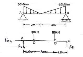
A6)
 Resolving forces vertically
∑fy = 0
RVA – 30 – 80 + RB = 0
RVA + RB = 110 --------------(1)
Resolving forces horizontally
∑fX = 0
RHA = 0
Taking moments at A
∑ MA = 0
(30 × 0.6) + [80 × (4.07 + 0.6)]- (6 × RB) = 0
18 + 373.6 – 6RB = 0
6RB = 391.6
RB= 65.267 kN
Put above value in equation (1)
RVA + RB = 110
RVA + 65.267 = 110
RVA = 110 – 65.267
RVA = 44.733 kN
Q7) Find support reactions for the loading as shown below:
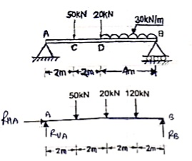
A7)
 Resolving forces vertically
∑fy = 0
RVA – 50 – 20 – 120 + RB = 0
RVA + RB = 190 ----------(1)
Resolving forces horizontally
∑fX = 0
RHA = 0
Taking moments at A
∑ MA = 0
(50 × 2) + (20 × 4) + (120 × 6) – 8RB = 0
100 + 80 + 720 – 8RB = 0
900 – 8RB = 0
RB – 112.5 kN 
Put above value in equation (1)
RVA + 112.50 = 190
RVA = 77.5 kN 
Q8) Explain sagging and hogging in beam?
 A8) The bending moment is considered as Sagging Bending Moment if it tends to bend the beam to a curvature having convexity at the bottom as shown in the Fig. Given below. Sagging Bending Moment is considered as positive bending moment
convexity
Sagging bending moment [Positive bending moment
Q9) Explain hogging in beams?
 A9) similarly the bending moment is considered as hogging bending moment if it tends to bend the beam to a curvature having convexity at the top as shown in the Fig. Given below. Hogging Bending Moment is considered as Negative Bending Moment.
Convexity
Hogging bending moment [Negative bending moment
Q10) Explain Point of Contra flexure [Inflection point]:
A10) Point of Contra flexure [Inflection point
It is the point on the bending moment diagram where bending moment changes the sign from positive to negative or vice versa.
It is also called ‘Inflection point’. At the point of inflection point or contra flexure the bending moment is zero.