UNIT 8
TORSIONAL MOTION
Q1) Explain power transmission in shaft?
A1) Power Transmitted by a shaft:
If T is the applied Torque and is the angular velocity of the shaft, then the power transmitted by the shaft is
P= Tw = 2 π NT /60
= 2 π NT / (60 x 103) Kw
Q2) Explain Reduction in weight:
A2)
Considering a solid and hollow shafts of the same length 'l' and density '' with di = 1/2 Do
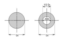
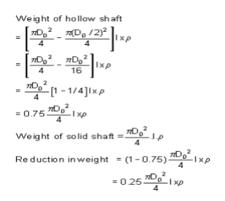
Hence the reduction in weight would be just 25%.
Q3) Explain Closed Coiled helical springs
A3) spring subjected to axial loads:
Definition: A spring may be defined as an elastic member whose primary function is to deflect or distort under the action of applied load; it recovers its original shape when load is released. Or Springs are energy absorbing units whose function is to store energy and to restore it slowly or rapidly depending on the particular application.
Important types of springs are:
There are various types of springs such as
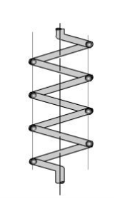
(i) Helical spring: They are made of wire coiled into a helical form, the load being applied along the axis of the helix. In these type of springs the major stresses is torsional shear stress due to twisting. They are both used in tension and compression.
(ii) Spiral springs: They are made of flat strip of metal wound in the form of spiral and loaded in torsion.
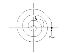
In this the major stresses are tensile and compression due to bending.
Q4) Explain Leaf springs?
A4) They are composed of flat bars of varying lengths clamped together so as to obtain greater efficiency. Leaf springs may be full elliptic, semi elliptic or cantilever types, In these type of springs the major stresses which come into picture are tensile & compressive.
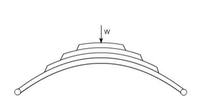
These types of springs are used in the automobile suspension system.
Uses of springs:
(a) To apply forces and to control motions as in brakes and clutches.
(b) To measure forces as in spring balance.
(c) To store energy as in clock springs.
(d) To reduce the effect of shock or impact loading as in carriage springs.
(e) To change the vibrating characteristics of a member as inflexible mounting of motors.
Q5) A moment of 1000 Nm is acting on a solid cylinder shaft with diameter 50 mm (0.05 m) and length 1 m. The shaft is made in steel with modulus of rigidity 79 GPa (79 109 Pa). Find maximum shear stress and angular deflection?
A5)
Maximum shear stress can be calculated as
τmax = T r / J
= T (D / 2) / (π D4 / 32)
= (1000 Nm) ((0.05 m) / 2) / (π (0.05 m)4 / 32)
= 40764331 Pa
= 40.8 MPa
The angular deflection of the shaft can be calculated as
θ = L T / (J G)
= L T / ((π D4 / 32) G)
= (1 m) (1000 Nm) / ((π (0.05 m)4 / 32) (79 109 Pa))
= 0.021 (radians)
= 1.2 o
Q6) A moment of 1000 Nm is acting on a hollow cylinder shaft with outer diameter 50 mm (0.05 m), inner diameter 30 mm (0.03 m) and length 1 m. The shaft is made in steel with modulus of rigidity 79 GPa (79 109 Pa). find Maximum shear stress The angular deflection of the hollow shaft?
A6)
Maximum shear stress can be calculated as
τmax = T r / J
= T (D / 2) / (π (D4 - d4) / 32)
= (1000 Nm) ((0.05 m) / 2) / (π ((0.05 m)4 - (0.03 m)4) / 32)
= 46.8 MPa
The angular deflection of the shaft can be calculated as
θ = L T / (J G)
= L T / ((π D4 / 32) G)
= (1 m) (1000 Nm) / ((π ((0.05 m)4 - (0.03 m)4) / 32) (79 109 Pa))
= 0.023 radian)
= 1.4 o
Q7) A 15 kW electric motor shall be used to transmit power through a connected solid shaft. The motor and the shaft rotate with 2000 rpm. The maximum allowable shear stress - τmax - in the shaft is 100 MPa.
A7)
The connection between power and torque can be expressed
P = 0.105 nrpm T
Where
P = power (W)
nrpm = speed of shaft (rpm)
Re-arranged and with values - the torque can be calculated
T = (15 103 W) / (0.105 (2000 rpm))
= 71 Nm
Minimum diameter of the shaft can be calculated by
Diameter of a Solid Shaft
Diameter of a solid shaft can calculate by the formula
D = 1.72 (Tmax / τmax)1/3
D = 1.72 ((71 Nm) / (100 106 Pa))1/3
= 0.0153 m
= 15.3 mm
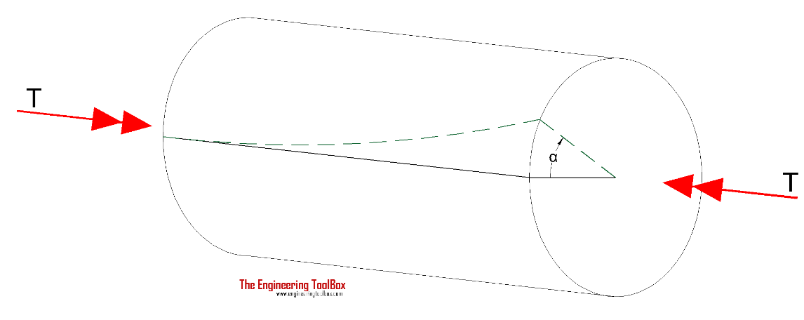
Q8) Explain Torsional Deflection of Shaft
A8)
The angular deflection of a torsion shaft can be expressed as
α = L T / (J G)
Where
α = angular shaft deflection (radians)
L = length of shaft (m, ft)
G = Shear Modulus of Rigidity - or Modulus of Rigidity (Pa, psf)
The angular deflection of a torsion solid shaft can be expressed as
α = 32 L T / (G π D4)
The angular deflection of a torsion hollow shaft can be expressed as
α = 32 L T / (G π (D4- d4))
The angle in degrees can be achieved by multiplying the angle θ in radians with 180 / π.
Solid shaft (π replaced)
αdegrees ≈ 584 L T / (G D4)
Hollow shaft (π replaced)
αdegrees ≈ 584 L T / (G (D4- d4)
Q9) Write the formula of Circular Shaft and Maximum Moment or Torque?
A9) Maximum moment in a circular shaft can be expressed as:
Tmax = τmax J / R
Where
Tmax = maximum twisting torque (Nm, lbf ft)
τmax = maximum shear stress (Pa, lbf/ft2)
R = radius of shaft (m, ft)
For a solid shaft
Tmax = (π / 16) τmax D3
For a hollow shaft
Tmax = (π / 16) τmax (D4 - d4) / D
Q10) Derive the derivation of torsional shaft?
A10)
Torsion equation or torsion constant is defined as the geometrical property of a bar’s cross-section that is involved in the axis of the bar that has a relationship between the angle of twist and applied torque whose SI unit is m4. The torsion equation is given as follows:
T/J= τ/r=GΘ/L
Torsion equation derivation
Following are the assumptions made for the derivation of torsion equation:
- The material is homogeneous (elastic property throughout)
- The material should follow Hook’s law
- The material should have shear stress proportional to shear strain
- The cross-sectional area should be plane
- The circular section should be circular
- Every diameter of the material should rotate through the same angle
- The stress of the material should not exceed the elastic limit
Consider a solid circular shaft with radius R that is subjected to a torque T at one end and the other end under the same torque.
T = Maximum twisting torque or twisting moment
D = Diameter of shaft
R = Radius of shaft
J = Polar moment of Inertia
τ= Maximum Permissible Shear stress (Fixed for given material)
G = Modulus of rigidity
θ= Angle of twist (Radians) = angle D'OD L = Length of shaft.
?= Angle D'CD = Angle of Shear strain

Than Torsion equation is: T/J = τ/R = G. θ /L
Let the shaft is subjected to a torque or twisting moment 'T'. And hence every C.S. Of this shaft will be subjected to shear stress.
Now distortion at the outer surface = DD'
Shear strain at outer surface = Distortion/Unit length tan? = DD'/CD
i.e. shear stress at the outer surface (tan? ) = DD'/L or = DD'/L ...(i)
Now DD' = R.θ or ?= R .θ /L ...(ii)
Now G = Shear stress induced/shear strain produced
G = τ / (R. θ /L);
Or; τ/R = G. θ /L …..(A);
This equation is called Stiffness equation.
Hear G, θ , L are constant for a given torque 'T'. That is proportional to R
If τ r be the intensity of shear stress at any layer at a distance 'r' from canter of the shaft, then;
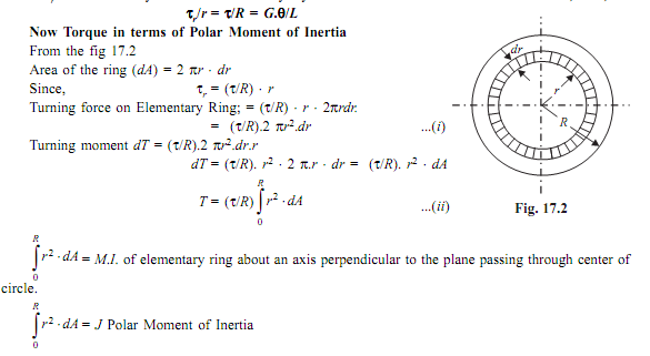
Now from equation (ii) T = (τ/R) J
Or τ/R = T/J; ..(B)
This equation is called as strength equation
The combined equation A and B; we get
T/J = τ/R = G. θ /L
This equation is called as Torsion equation.
From the relation T/J = τ/R We have T = τ .J/R = τ .ZP
For the given shaft IP and R are constants and IP/R is thus constant and is called as POLAR MODULUS(ZP). Of the shaft section.
Polar modulus of section is thus measure of strength of shaft in the torsion.
TORSIONAL RIGIDITY or Torsional Stiffness (K): = G.J/L = T/θ