Unit - 6
PID controllers and Control system components
Q1) The block diagram of a system using PI controllers is shown in the figure. Calculate:
(a). The steady state without and with controller for unit step input?
(b). Determine TF of newly constructed sys. With controller so, that a CL Poles is located at -5?

Fig 1 System with PI controller
A1)
(a). Without:
C(S)/R(S) = 0.2/(S + 1)
C(S) = R(S) 0.2/(S + 1) + 0.2
For unit step
Ess = 1/1 + Kp
Kp = lt G(S)
S 0
= lt 0.2/(S + 1)
S 0
Kp = 0.2
Ess = 1/1.2 = 5/6 = 0.8
(b). With controller:
Gc(S) = Kp + Ki/S
G’(S) = Gc(S).G(S)
= ( Kp + Ki/S )0.2/(S + 1)
= (KpS + Ki)0.2/S(S + 1)
Ess = 1/1 + Kp = 0
So, the value of ess is decreased.
(b). Given
Kpi/Kp = 0.1
G’(S) = (Kp + Ki/S)(0.2/S + 1)
= (KpS + Ki)0.2/S(S + 1)
As a pole is to be added so, we have to examine the CE,
1 + G’(S) = 0
1 + (Kp + Ki)0.2/S(S + 1) = 0
S2 + S + 0.2KpS + 0.2Ki = 0
S2 + (0.2Kp + 1)S + 0.2Ki = 0
Given,
Kpi = 0.1Ki
Kp = 10Ki
S2 + (2Ki + 1)S + 0.2Ki = 0
Pole at S = -5
25 + (2Ki + 1)(-5) + 0.2Ki = 0
-10Ki – 5 + 25 + 0.2Ki = 0
-9.8Ki = -20
Ki = 2.05
Kp = 10Ki
= 20.5
Now,
G’(S) = (KpS + Ki)(0.2)/S(S + 1)
= (20.5S + 2.05)(0.2)/S(S + 1)
G’(S) = 4.1S + 0.41/S(S + 1)
Q2) The block diagram of a system using Pd controller is shown, the PD is used to increase ξ to 0.8. Determine the T.F of controller?

Fig 2 System with PD Controller
A2)
Kp = 1
Without controller:
C(S)/R(S) = 16/S2 + 1.6S + 16
wn = 4
2 ξwn = 16
ξ = 1.6/2 x 4 = 0.2
With derivative:
ξS = 0.2 to 0.8
Undamped to critically damped,
G’(S) = (1 + KdS)(16)/(S2 + 1.6S)
CE:
S2 + 1.6S + 16(1 + KdS) = 0
S2 + (1.6 + Kd)S + 16 = 0
2 ξwn = 1.6 + Kd1.6
wn = 4
ξS = 0.8
2 x 4 x 0.8 = 1.6 + Kd1.6
4.8/16 = Kd
Kd = 0.3
TF = (1 + 0.3S)16/S(S + 16)
Q3) Explain PID characteristics?
A3)
The manual method for obtaining the characteristics is to set Ki and Kd to zero.
Keeping the values zero we set Kp such that there are oscillations at output. The below figure shows that when Kp is reduced to half the value at which it gave oscillations the output decays.
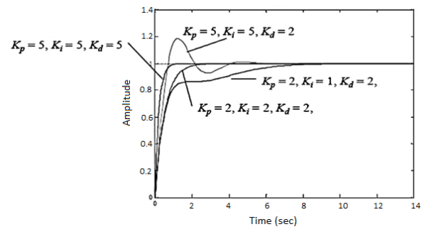
Fig 3 PID characteristics
If Ki is increased the system becomes unstable. So, Ki can be increased to an extent. The value of Kd can be increased so that the output reaches its reference values. If Kd is increased more than it causes overshoot. The system which are overdamped require Kp to be half the value which was making oscillations at output.
Q4) What is the effect of KP, Ki, Kd on performance parameters?
A4) 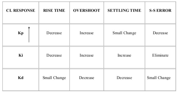
Q5) Explain concept of Zeigler-Nicholas Method?
A5)
They proposed the rules for determining values of proportional gain kp, derivative time Td and integral time Ti. They have proposed from (1) methods.
1) First Method: The basic PID controller is shown in figure below. In this method a unit step response of a plant. Is obtained if the plant has neither integrator non dominant complex conjugal poles, then the output step curve is of shape s. As shown below. These curves are generated experimentally.
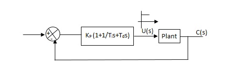
Fig 4 PID Controller
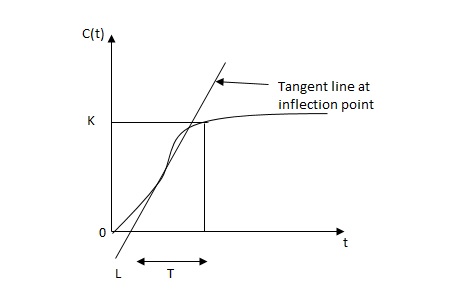
Fig 5. S-Shaped Response Curve

c(s) / l(s) = ke-l1s / ts+1
The values of KP, Ti and td should be set according to the table suggested by Ziegler Nichols tuning rules shown below.
Type of controller
Types of controller | Kp | Ti | Td |
|
P | T/L | 00 | 0 |
|
PI | 0.9T/L | L/0.3 | 0 |
|
PID | 1.2T/L | 2L | 0.5L |
|
Controller gain Gc(s)= kp(1+1/Tis+Tds)
= 1.2T / L(1+1 / 2LS+0.5 LS)
= 1.2t/l+0.6t / L2S+0.6TS
= 0.6T(2/L+1/L2S+S)
Gc(s) = 0.6 T(S+1/L)2/S
Thus, the PID controller has a pole at the origin and double zeros at S=-1/ L
2) Second Method -
1) Firstly, set Ti= and Td=0
2) Use proportional control action only, increase kp from 0 to Kcr (Critical value).
3) Then Kcr and pcr (period) are determined experimentally.

Fig 6. Closed loop with proportional controller
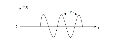
Fig 7. Sustained oscillation with period pcr.
4) For this method Ziegler Nichols suggested new set of values for kp ,ti and td shown in table below.
Types of controller | KP | TI | Td |
P | 0.5Kcr |  | 0 |
PI | 0.45 KCR | 1/1.2PCR | 0 |
PID | 0.6KCR | 0.5PCR | 0.125PCR |
|
|
|
|
GC(S) = KP(1.1/Tis+Tds)
=0.6 Kcr(1+1/0.5PcrS+ 0.125 PCRS)
=0.075 KcrPcr(s+4/Pcr)2 / s
Thus, the PID controller has a pole at the origin and double zeros at s= -4/Pcr
Q6) What do understand by industrial automation?
A6)
It is basically managing all the work done required with the help of machines, robots etc. This technology uses automatic control devices such as robots which do not require any human assistance. These devices have PLC, PAC etc. The advantages of industrial automation are listed below
1) They increase the production rate as the machines are capable to produce more quantity in less time.
2) As all the work done is through machines the labour requirement is reduced and hence the investment on employee is reduced. This reduces the cost of operation.
3) The quality of product becomes better as the programmed machines work and produce same and exact required products.
4) There is no need for manual assistance.
5) It is safer.
Q7) Derive expression for proportional controller?
A7)
Proportional means scalar Multiplier.
Gc(S) = Kp Stability can be controlled
Q. G(S) = 1/S(S + 8)
CLTF = 1/S2 + 8S + 1
w2n = 1
wn = 1
2ξWn = 8
ξ = 4
ξ>/1 so, overdamped.
Now introducing Gc(S) = K
G’(S) = Kp/S(S + 8)
CLTF = Kp/S2 + 8S + Kp
wn = √Kp
2 ξwn = 8
ξ = 4/√Kp
If,
Kp = 16; ξ = 1; critically damped
Kp> 16; ξ< 1; undamped
Kp< 16; ξ> 1; overdamped
Q8) Explain derivative controller?
A8)
Gc(S) = Kd(S)
They are used to improve the stability.
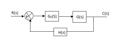
Fig 8 System with D controller
G’(S) = KdS/S2(S + 10)
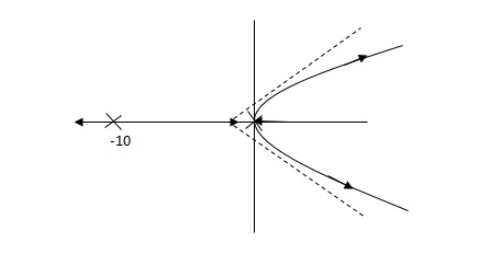
Fig 9a Root locus without controller
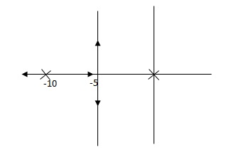
Fig 9b Root locus for system with D controller
(b) is stable i.e. more stable than the (a).
Disadvantage –
It increases the steady state i.e. o/p will not track the input at steady state.
Q9) What is the need of IoT in automation industry explain?
A9)
IoT is Internet of Things which means the system can work on real time data. Having IoT helps to collect data and also data acquisition. This can improve the efficiency and hence the performance and accuracy. This makes system well organised and flexible. These are internet connected devices which are capable of collection real time data which helps in business and consumers also.
These devices can be used at homes like smoke detector, some smart music systems. Some which work on voice inputs like smart light bulbs. They are also used in personal physical training devices which keep a check on fitness and let the person know.
IoT Gateway devices behave as a connection bridge between IoT Sensor Network and Cloud Server. IoT Gateway devices are appearing as essential elements in bringing next-generation devices to the IoT. They assist to merge protocols for networking, helps to analyse storage and edge analytics on the data and make possible data flow safely between edge devices and the cloud.
These IoT based industrial automations are real time so accurate and precise. They can be used anywhere and any time as they are clouds. They are secure than any other systems. The improve efficiency and reduce the production cost.
They allow predictions too. As they are always collecting the real time data so they can predict if any problem is about to arise. So, that preventive measures can be thought beforehand.
Q10) What is dead zone?
A10)
Dead Zone: In this the system will not respond to the given input until the input reaches a particular level.
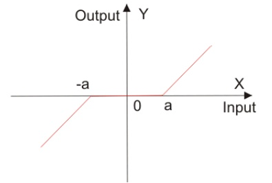
Fig 10 Dead Zone
This error reduces accuracy of system and degrades its performance. This nonlinearity can be seen in diodes, actuators.