Unit - 2
Major Electrical Equipment's in Power Station & Underground Cables
Q1) Explain alternators and exciters?
A1)
Alternators
- Each alternator is coupled to a steam turbine & converts mechanical energy of the turbine into electrical energy.
- The electrical output from the alternator is delivered to the bus bar through transformer.
- The alternators may be hydrogen or air cooled.
Exciter
- Exciter is a dc compound generator and mounted on the same shaft of the steam turbine and generator.
- It continuously supply the field winding of the alternator.
Q2) Explain DC and AC excitation?
A2)
DC excitation
DC excitation system has two exciters – the main exciter and a pilot exciter. The exciter output is adjusted by an automatic voltage regulator (AVR) for controlling the output terminal voltage of the alternator. The current transformer input to the AVR ensures limiting of the alternator current during a fault.
The AC excitation system consists of an alternator and thyristor rectifier bridge directly connected to the main alternator shaft. The main exciter may either be self-excited or separately excited.
Q3) Power transformers voltage regulators?
A3)
- A power transformer is a static machine used for transforming power from one circuit to another without changing frequency.
- Since there is no rotating or moving part the transformer is a static device. Transformer operates on an ac supply.
- A transformer works on the principle of mutual induction.
The measure of how well a power transformer maintains constant secondary voltage over a range of load currents is called the transformer’s voltage regulation. It can be calculated from the following formula:
Regulation percentage – E no-load – E full-load/ E full-load (100%)
Q4) Write a short note on current transformers?
A4)
Current transformers
Current transformers are used to measure currents of high magnitude. These transformers step down the current to be measured, so that it can be measured with a normal range ammeter.
A Current transformer has one or few numbers of primary turns.
The primary winding is just a conductor, or a bus bar placed in a hollow core as shown in the figure.
The secondary winding consists of large number turns accurately wound for a specific turn’s ratio. Thus, the current transformer steps up (increases) the voltage while stepping down (lowering) the current.
The secondary current is measured with the help of an AC ammeter.
The turns ratio of a transformer is
NP / NS = IS / IP
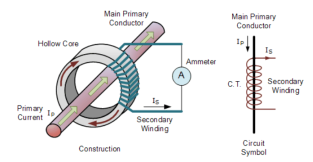
Current transformer
Q5) Write a short note on potential transformer?
A5)
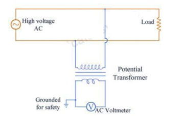
Potential transformers known as voltage transformers are basically step down transformers with extremely accurate turns ratio. Potential transformers step down the voltage of high magnitude to a lower voltage which can be measured with standard measuring instrument. These transformers have large number of primary turns and smaller number of secondary turns.
A potential transformer is typically expressed in primary to secondary voltage ratio.
Q6) Explain lightning arresters?
A6)
The device which is used for the protection of the equipment at the substations against travelling waves, such type of device is called lightning arrester or surge diverter.
When travelling wave reaches the arrestor, its sparks over at a certain prefixed voltage as shown in the figure. The arrestor provides conducting path to the waves of relatively low impedance between the line and the ground.
The lightning arrester provides a path of low impedance only when the travelling surge reaches the surge diverter, neither before it nor after it. The insulation of the equipment can be protected if the shape of the voltage and current at the diverter terminal is like the shape shown below.
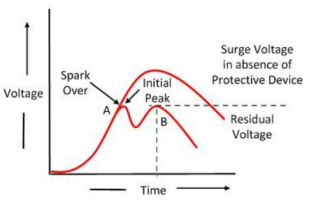
Figure. Voltage characteristics
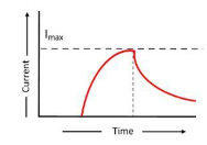
Figure. Current characteristics
Q7) Write a short note on PLCC?
A7)
Power Line Carrier Communication, often called PLCC, is used for speech data transmission as well as protection of Transmission Lines.
PLCC is mainly for telemetry and telecontrol in modern electrical Power System.
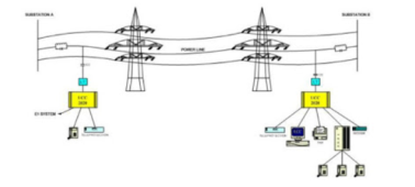
Figure. PLCC
Power Line Carrier Communication is used for the Carrier Tripping and Direct Tripping in case of Distance Protection.
Whenever there is a fault in the line, it is important to isolate the fault. Merely tripping of breaker at one end of line cannot isolate the fault. Breaker at the other end of line should also open.
Let us consider a simple diagram as shown below.
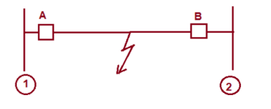
Figure. Fault
In case of fault, breaker A and B should open.
Let us assume that, the fault is being sensed by relay at station 1. This relay should issue trip command to breaker A and send trip signal to the remote end. This trip signal to remote end is called Direct Trip(DT) signal.
On reception of DT signal, master trip relay at Remote station 2 actuates which in turn actuates breaker B. This trip signal that is DT signal is sent through PLCC.
Q8) Explain the construction of cables?
A8)
Construction of cables:
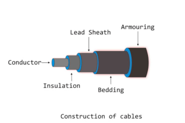
Figure. Cable construction
Core or Conductors
A cable contains one or more than one core conductor which depends upon the type of service intended. The conductors are made of tinned copper or aluminium and stranded to provide flexibility to the cable.
Insulators
Each core or conductor is provided with suitable thickness of insulation, the thickness of layer depends on the voltage withstood by the cable. The materials used for insulation are impregnated paper, varnished cambric or rubber mineral compound.
Metallic Sheath
To protect the cable from moisture, gases or other damaging liquids acids or alkalis in the soil and atmosphere, a metallic sheath of lead or aluminium is provided.
Bedding
Over the metallic sheath a layer of bedding is applied which consists of fibrous material like jute or hessian tape. The purpose of bedding is to protect the metallic sheath against corrosion and from mechanical injury due to armouring.
Armouring
Over the bedding, armouring is provided which consists of one or two layers of galvanised steel wire or steel tape. Its purpose is to protect the cable from mechanical injury while laying it and while handling.
Serving
To protect armouring from atmospheric conditions, a layer of fibrous material like bedding is provided over the armouring. This is known as serving
Q9) Explain the classification cables?
A9)
The classification of Underground cables is done based on several criteria. Various aspects are taken while classification include:
- Number of conductors in the cable
- Voltage rating of the cable
- Construction of cable
- Type and thickness of insulation used
- Installation and Laying of the cables
Q10) Explain the capacitance of single core cable?
A10)
A single core cable is equivalent to two co-axial cylinders. The inner cylinder is conductor itself while the outer cylinder is the lead sheath. The lead sheath is always at earth potential.
Let d= Conductor diameter
D = Total diameter with sheath
The co-axial cylindrical form of cable and its section are shown in the figure.
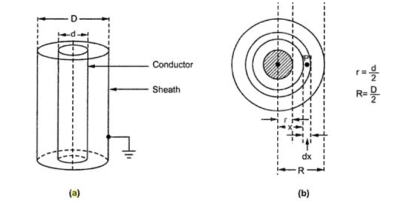
Figure. Capacitance of single core cable
Let Q = Charge per meter length of conductor in Coulombs
ε = Permittivity of material between core and sheath
Now ε = εo εr
Where εo = Permittivity of free space = 8.854 × 10⁻¹² F / m
εr = Relative permittivity of the medium
Consider an elementary cylinder with radius x and axial length of 1 m. The thickness of the cylinder is dx.
In Gauss’s theorem, the lines of flux emanating due to charge Q on the conductor are in radial direction and total flux lines are equal to the total electric charge possessed.
As lines are in radial direction, the cross-sectional area through which lines pass is surface area. For a cylinder with radius x, the surface area is (2 Π × axial length) m2.
Flux density = Q/surface area = Q/ 2πx C/m2
The electric field intensity at any point P on the elementary cylinder is giver by,
Gx = Dx/  where Dx = Electric flux density
= Q/ 2π x  = Q/ 2π x
  o
o  V/m
V/m
Hence the work done in moving a unit charge through a distance dx in the direction of an electric field is gx dx.
Hence the work done in moving a unit charge from the conductor to the sheath is the potential difference between the conductor and the sheath is given by,
V =  dx =
dx =  dx
dx
Q/ 2π x  o
o 
 dx /x = Q/ 2π x
  o
o  [ ln x] d/2 D/2
= Q/ 2π x  o
o  [ ln D/2 – ln d/2]
V = = Q/ 2π x  o
o  ln[D/d] = = Q/ 2π x
  o
o  ln[R/r]
The capacitance of a cable is given by,
C = Q/V = [Q/ 2π  o
o  ln (R/r)]
C = 2π  o
o  / ln[R/r] F/m = 2π
  o
o  / ln [ D/d] F/m
Q11) Explain dielectric stress of single core cable?
A11)
Under operating conditions, the insulation of a cable is subjected to electrostatic forces. This is known as dielectric stress. The dielectric stress at any point in a cable is in fact the potential gradient or electric intensity at that point.
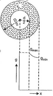
Figure. Single core cable.
Consider a Capacitance of Single Core Cable with core diameter d and internal sheath diameter D. The electric intensity at a point x metres from the centre of the cable is
Ex = Q/2π 
 x volts/m.
By definition, electric intensity is equal to potential gradient. Therefore, potential gradient g at a point x metres from the centre of cable is
g=Ex
g=Q/2π 
 x -------------------------------(i)
The potential difference V between conductor and sheath is
V = Q/ 2π 
 log e D/d
Q = 2π 
 V / log e D/d -----------------------------(ii)
Substituting the value of Q from exp. (ii) in exp. (i), we get,
g = = 2π 
 V / log e D/d / 2π
 x = V / x log e D/d -----------------(iii)
It is clear from exp. (iii) that potential gradient varies inversely as the distance x. Therefore, potential gradient will be maximum when x is minimum i.e., when x = d/2 or at the surface of the conductor. On the other hand, potential gradient will be minimum at x = D/2 or at sheath surface.
Maximum potential gradient is
Gmax = 2V / d log e D/d volts/m
Minimum potential gradient is
Gmin = 2V/ D log e D/d volts/m
Q12) Explain intersheath cabling and capacitance cabling?
A12)
Intersheath Grading
In this method, instead of using various dielectrics and having a composite dielectric, we use a homogeneous dielectric material. However, to distribute the stress properly, we use extra metallic sheaths between the conductor and the main sheath. These intermediate sheaths are called ‘intersheaths’. These intersheaths are then held at adequate voltage levels. This method improves voltage distribution in the dielectric of the cable and consequently uniform potential gradient is obtained.
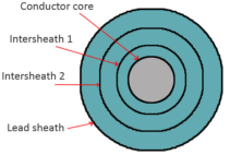
Figure . Intersheath grading
Capacitance grading
Capacitance grading is done by employing various layers of different dielectrics having different permittivity’s between the core and the sheath. Hence the dielectric insulation provided is no longer homogeneous, but composite.
The various layers are arranged so that the permittivity decreases from the surface of the conductor to the sheath of a cable that is the permittivity of dielectric is inversely proportional to the distance from the center.
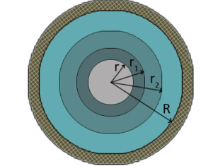
Figure. Capacitance grading