Unit - 1
Performance of Transmission Line
Q1) A 100 km, 50Hz, 3 phase line with r = 0.03ohm, X= 0.10 ohm and C = 0.01  F per km of line length has a load of 2 MW at 0.8 power factor lag at the receiving end. The receiving end is maintained at 11kV by connecting at receiving end a bank of static capacitors rated 1 MVAR at 11kV. Calculate using nominal π-method, the voltage and current at the sending end of the line.
A1)


For a nominal π-network, the generalised ckt. Constants are


Capacitor current,

Receiving end current,

Sending end voltage,


Sending end current,


Q2) A 200 km, 3 phase, 50Hz transmission line has the following data.
A=D =0.938<1.2°, B=131.2<72.3 ohms/phase, C=0.001<90° siemens/phase. The sending end voltage is 230kV. Determine a) the receiving end voltage when the load is disconnected. b) the line charging current
c) the maximum power that can be transmitted at a receiving end voltage of 220kV and the corresponding load reactive power required at the receiving end.
A2)
Sending end phase voltage,

When the load is disconnected,
Ir = 0
Vs = AVr + BIr
192790<0=(0.938<1.2)×Vr + B×0

Vr = 141570<-1.2V
Vrl =  r =
r =  × 141570 = 245200 V
Line charging current,
Ic = C Vr
=0.001<90˚×141570<-1.2=141.57,88.8 A
Maximum power that can be transmitted for Vrl = 220kV and Vs = 230 kV


Corresponding reactive power required at the receiving end,

Q3) A 3 phase transmission line has a resistance per phase of 5 ohm and an inductive reactance of 15 ohm per phase. Determine the load which the line will be supplying at 132kV and 0.8 pf lagging. The sending end voltage is 140kV.
If a synchronous phase modifier is connected in parallel with the load to improve the power factor to 0.95 lagging, determine the leading MVAR supplied by the synchronous phase modifier. Receiving end voltage and load remain unchanged.
A3)
Power factor of the load, 
Load power factor angle, 
For short transmission line, A=1


For receiving end power circle diagram
Radius of circle = 
Coordinates of the centre of the power circle are
Horizontal coordinate = 

Vertical Coordinate =

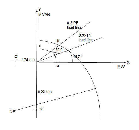
Take scale 1 cm = 200MW horizontally and 1cm = 200MVAR vertically.
Radius of the circle = 1168.8 / 200 = 5.85 cm
Horizontal coordinate = -347.8 / 200 = -1.74 cm
Vertical coordinate = -1045.6 / 200 = -5.23 cm
And draw circle diagram.
From origin 0, draw a line OP inclined at an angle cos-1 0.8 =36.9° with the horizontal cutting the circle at pt. b.
From point b, draw a perpendicular ba on the horizontal axis.
Power supplied at 0.8 pf lagging = Oa = 0.3×200 = 60 MW
Now draw another line OP' inclined at angle cos-1 0.95 = 18.2° with the horizontal cutting the vertical line ba at c.
Total leading MVAR supplied by the synchronous phase modifier
=bc = 0.1 ×200 = 20 MVAR
Q4) A 132 kV, three phase line has the following line parameters.
A=0.98<30°, B=110<75° ohm per phase. If the receiving end voltage is 132kV, determine sending end voltage and power angle if a load 50MVA at 0.8 pf lagging is being delivered at receiving end.
A4)
Given data, VrL = 132 kV A = 0.90<30˚ B=110<75˚ S = 50 mVA
P.F cos =0.8 lagging Vs= ?
Vs = AVr + BIr -----------(1)
Is = CVr + DIr -----------(2)
Sending end voltage (Vs) = AVr + BIr
Vrp = 


Q5) Determine sending end complex power of a transmission line delivering 50mVA at 132kV, 50Hz and 0.8 pf lagging. The ABCD constants of transmission line are A=D=0.9855<0.32, B=67.68<68.6g ohm.
A5)
Given data-
S=50 MVA
VL = 132kV
f = 50 Hz
p.f. = 0.8 lagg
A = D = 0.9855<0.32
B = 67.68 < 68.69 ohm


OR


AD – BC =1


=


Q6) The voltage at Bus A (reference) is 522 kV at an angle of -15 degrees. The voltage at Bus B is 518 kV at an angle of -18 degrees. Total impedance of the transmission path between the buses is 50 ohms. What is (a) the real power flow, and (b) what is its direction?
A6)
(a) PR =  sin
sin = {(522) (518)/50} sin (-150-(-180)) = 283 MW
(b) Direction of flow is from bus A to B
Q7) Calculate the a) real power, and b) it’s direction of flow using the following information: Bus A voltage is 235 kV at an angle of -23 degrees with a power factor of 0.79 Bus B voltage is 237 kV at an angle of -21 degrees with a power factor of 0.85 Total impedance of the transmission path between the buses is 45 ohms
A7)
(a) PR =  sin
sin = {(235) (237)/45} sin (-230-(-210)) = -43.2 MW
(b) Direction of flow is from bus B to A
Q8) Bus A has a voltage of 234 kV at an angle of -18 degrees, and Bus B voltage is 239 kV at an angle of -25 degrees. If the impedance of the transmission path is 45 ohms, what is (a) the reactive power flow between the buses, and (b) in what direction is the reactive power flowing?
A8)
(a) PQ =  cos
cos  = {(239) (239-234)/45} cos {(-250) - (-180)} = 26.4 MVAR
(b) Flow is from Bus B to Bus A
Q9) Calculate the a) reactive power between Bus A and Bus B, and b) it’s direction of flow using the following information: Bus A voltage is 547 kV at an angle of -15 degrees with a power factor of 0.78 Bus B voltage is 544 kV at an angle of -18 degrees with a power factor of 0.81 Total impedance of the transmission path is 86 ohms
A9)
(a) PQ =  cos
cos  = {(547) (547-544)/86} cos {(-150) - (-180)} = 19.07 MVAR
(b) Flow is from Bus A to Bus B
Q10) The single-phase transmission line is now supplying 8 kV to an 800 kVA, 0.9 PF lagging single-phase load. (a) What is the sending end voltage and current of this transmission line? (b) What is the efficiency of the transmission line under these conditions? (c) What is the voltage regulation of the transmission line under these conditions?
A10)
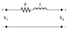
At 50 km length, we can treat this transmission line as a “short” line and ignore the effects of the shunt admittance. The corresponding equivalent circuit is shown below.
The transmission line is supplying a voltage of 8 kV at the load, so the magnitude of the current flowing to the load is
I = S/V = 800kVA/8kV = 100A
(a) If we assume that the voltage at the load is arbitrarily assigned to be at 0° phase, and the power factor of the load is 0.9 lagging, the phasor current flowing to the load is I = 100 ∠-25.8° A . The voltage at the sending end of the transmission line is then
Vs= VR + ZI
Vs= 8000∠0°+(2.1 +j 32.3) (100∠-25.8°)
VS= 10000∠16.4°
(b) The complex output power from the transmission line is
Sout= VR I* = (8000∠0°) ((100∠-25.8°) *= (800000 ∠25.8°) VA
Therefore, the output power is P OUT = 800 cos25.8°= 720 kW
The complex input power to the transmission line is
Sin= Vs I* = (10000∠16.4°) (100∠-25.8°) * = (1000000 ∠25.8°) VA
Therefore the input power is PIN =1000 cos42.2°= 741 kW
The resulting efficiency is
η = [Pout/Pin] x100% = 97.2%
(c) The voltage regulation of the transmission line is
VR = [Vs-VR/VR]x100% = 25%
Q11) The underground cable is now supplying 8 kV to an 800 kVA, 0.9 PF lagging single-phase load. (a) What is the sending end voltage and current of this transmission line? (b) What is the efficiency of the transmission line under these conditions? (c) What is the voltage regulation of the transmission line under these conditions?
A11)
At 50 km length, we can treat this transmission line as a “short” line and ignore the effects of the shunt admittance. (Note, however, that this assumption is not as good as it was for the overhead transmission line. The higher shunt admittance makes its effects harder to ignore.) The transmission line is supplying a voltage of 8 kV at the load, so the magnitude of the current flowing to the load is
I =S/V = 100A
(a) If we assume that the voltage at the load is arbitrarily assigned to be at 0° phase, and the power factor of the load is 0.9 lagging, the phasor current flowing to the load is I = 100 ∠−25.8 ° A. The voltage at the sending end of the transmission line is then
Vs= VR + ZI
Vs= 8000∠0°+(2.1 +j 16.05) (100∠-25.8°)
VS= 8990 ∠8.7°
(b) The complex output power from the transmission line is
Sout= VR I* = (8000∠0°) ((100∠-25.8°) *= (800000 ∠25.8°) VA
Therefore, the output power is P OUT= 800 cos25.8°= 720 kW
The complex input power to the transmission line is
Sin= Vs I* = (8990∠8.7°) (100∠-25.8°) * = (899000 ∠34.5°) VA
Therefore, the input power is PIN= 899 cos34.5°= 740.9 kW
The resulting efficiency is
η = [Pout/Pin] x100% = 97.2%
(c) The voltage regulation of the transmission line is
VR = [Vs-VR/VR]x100% = 12.4 %
Q12) A 138 kV, 200 MVA, 60 Hz, three-phase, power transmission line is 100 km long, and has the following characteristics: r = 0.103 Ω/km x = 0.525 Ω/km y = 3.3 × 10⁻⁶ S/km (a) What is per phase series impedance and shunt admittance of this transmission line?
(b) Should it be modeled as a short, medium, or long transmission line?
(c) Calculate the ABCD constants of this transmission line.
(d) Sketch the phasor diagram of this transmission line when the line is supplying rated voltage and apparent power at a 0.90 power factor lagging.
(e) Calculate the sending end voltage if the line is supplying rated voltage and apparent power at 0.90 PF lagging.
(f) What is the voltage regulation of the transmission line for the conditions in (e)?
(g) What is the efficiency of the transmission line for the conditions in (e)?
A12)
(a) The per-phase series impedance of this transmission line is

The per-phase shunt admittance of this transmission line is

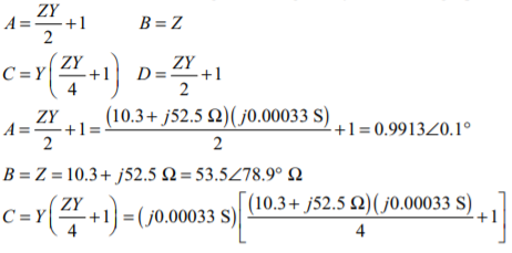
(b) This transmission line should be modeled as a medium length transmission line. (c) The ABCD constants for a medium length line are given by the following equations:

(d) The phasor diagram is shown below:

(e) The rated line voltage is 138 kV, so the rated phase voltage is 138 kV / 3 = 79.67 kV, and the rated current is

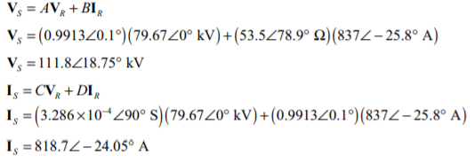
If the phase voltage at the receiving end is assumed to be at a phase angle of 0°, then the phase voltage at the receiving end will be VR = 79.67 ∠ 0 ° kV, and the phase current at the receiving end will be IR = 837 ∠−25.8 ° A. The current and voltage at the sending end of the transmission line are given by the following equations:
(f) The voltage regulation of the transmission line is

(g) The output power from the transmission line is

The input power to the transmission line is

The resulting efficiency is

Q13) A 50 Hz three phase transmission line is 300 km long. It has a total series impedance of 23 + 75j Ω and a shunt admittance of j500 μS. It delivers 150 MW at 220 kV, with a power factor of 0.88 lagging. Find the voltage at the sending end using (a) the short line approximation. (b) The medium-length line approximation. (c) The long line equation. How accurate are the short and medium-length line approximations for this case?
A13)
(a) In the short line approximation, the shunt admittance is ignored. The ABCD constants for this line are:
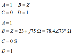
The receiving end line voltage is 220 kV, so the rated phase voltage is 220 kV / √3 = 127 kV, and the current is

If the phase voltage at the receiving end is assumed to be at a phase angle of 0°, then the phase voltage at the receiving end will be VR = 127 ∠0° kV, and the phase current at the receiving end will be IR = 394 ∠−28.4° A. The current and voltage at the sending end of the transmission line are given by the following equations:
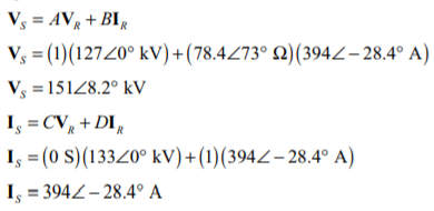
(b) In the medium length line approximation, the shunt admittance divided into two equal pieces at either end of the line. The ABCD constants for this line are:


The receiving end line voltage is 220 kV, so the rated phase voltage is 220 kV / √3 = 127 kV, and the current is

If the phase voltage at the receiving end is assumed to be at a phase angle of 0°, then the phase voltage at the receiving end will be VR = 127 ∠0° kV, and the phase current at the receiving end will be IR = 394 ∠−28.4° A. The current and voltage at the sending end of the transmission line are given by the following equations:
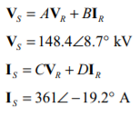
(c) In the long transmission line, the ABCD constants are based on modified impedances and admittances:
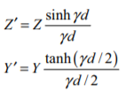
And the corresponding ABCD constants are

The propagation constant of this transmission line is


The modified parameters are

And the ABCD constants are
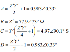
The receiving end line voltage is 220 kV, so the rated phase voltage is 220 kV / √3 = 127 kV, and the current is

If the phase voltage at the receiving end is assumed to be at a phase angle of 0°, then the phase voltage at the receiving end will be VR = 127 ∠0° kV, and the phase current at the receiving end will be IR = 394 ∠−28.4° A. The current and voltage at the sending end of the transmission line are given by the following equations:
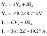
The short transmission line approximate was rather inaccurate, but the medium and long line models were both in good agreement with each other
Q14) A 60 Hz, three phase, 110 kV transmission line has a length of 100 miles and a series impedance of 0.20 + j0.85 Ω/mile and a shunt admittance of 6x10⁻⁶ × S/mile. The transmission line is supplying 60 MW at a power factor of 0.85 lagging, and the receiving end voltage is 110 kV. (a) What is the voltage, current, and power factor at the receiving end of this line? (b) What is the voltage, current, and power factor at the sending end of this line? (c) How much power is being lost in this transmission line? (d) What is the current angle δ of this transmission line? How close is the transmission line to its steady-state stability limit?
A14)
This transmission line may be considered to be a medium-line line. The impedance Z and admittance Y of this line are:

The ABCD constants for this line are:


(a) Assuming that the receiving end voltage is at 0°, the receiving end phase voltage and current are.
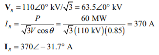
The receiving end power factor is 0.85 lagging. The receiving end line voltage and current are 110 kV and 370 A, respectively.
(b) The sending end voltage and current are given by

The sending end power factor is cos [15.35- (-26)] =cos 41.4= 0.751 lagging
The sending end line voltage and current are √3 (87.8 kV) =152 kV and 342 A, respectively.
(c) The power at the sending end of the transmission line is

The power at the receiving end of the transmission line is

Therefore, the losses in the transmission line are approximately 7.8 MW.
(d) The angle δ is 15.35°. It is about 1/4 of the way to the line’s static stability limit.