Unit - 3
Per unit system and Load Flow Analysis
Q1) A 30 MVA, 11kV generator has a reactance of 0.2 referred to its ratings as bases. Determine per unit reactance when referred to base kVA, new 50000 kVA and base kV of 33kV.
A1)
Old base KVA = 30000kVA
(MVA)B = 30 MVA
Old base kV = 11 kV
Old per unit impedance, Zpu old = 0.2 pu
New base kVA = 50000 KVA
(MVA)B new = 50 MVA


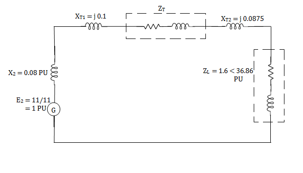
Q2) The following system represents a single line diagram of power system. The rating of connected component are given on a single line diagram. Choose 100 MVA common base and 11KV as voltage base on generator site. Draw per unit impedance diagram.

A2)

Generator-


Transformer 1-

Transformer 2-

Load-


Load impedance, 


Transmission line-


Q3) If the resistance in ohm is 5 ohm, find the Per unit value. Given base KVA =10 and base kV=11.
A3)
Base kVA = 10
(MVA)B = 10×10-3 (kV)B = 11


Q4) A single phase transformer is rated as 2.5kVA, 11/0.4 kV. If the leakage reactance is 0.96ohm when referred to low voltage side, then determine its leakage reactance in per unit.
A4)
(kVA)B = 2.5, (MVA)B = 2.5 ×10⁻³ (kV)B = 0.4


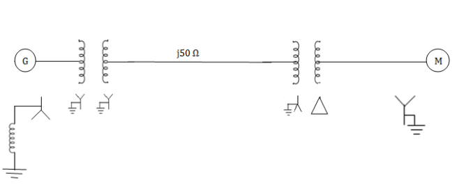
Q5) Draw the Per unit impedance diagram for the power system shown, neglect resistance and user base of 100MVA, 220kV in 50 ohm line. The rating of the generator motor and transformers are: Generator: 40 MVA, 25kV, X = 20%
Motor: 50MVA, 11kV, X =30%
 : 40 MVA, 33
 -220
-220 kV, X=15%
 30 MVA, 11
 - 220
- 220 kV, X=15%
A5)
(MVA)B =100MVA, (kV)B = 220 kV


Q6) A simple power system is shown in figure. Redraw the system when per unit impedances are represented on a common 5,000 VA base and common system base voltage of 250V.
A6)
Base MVA = 5×10⁻³ MVA
Base kV for generator circuit = 250×10-3 kV
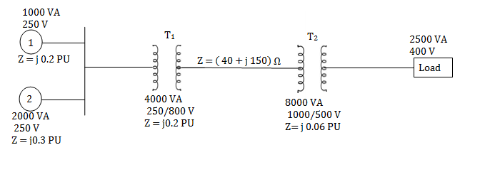
Per unit impedances of machine 1 and 2


Per unit reactance of Transformer T1


Per unit reactance of Transformer T2

Per unit load MVA (pu) = 2.5/5 = 0.5 pu

Q7) For the system shown in the figure determine the generator voltage. Take the base as 100 MVA, 15kV on generator terminals.

A7)
MVAB = 100 MVA
KVB = 15 kV on generator terminals
Generator-


Load-


Actual generator terminal voltage,


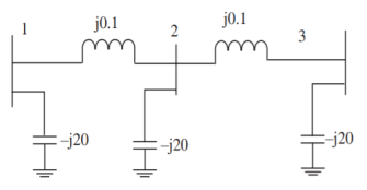
Q8) The network shown in Figure has impedance in pu as indicated, the shunt admittance is –j20 at each bus. The diagonal element of Y22
A8)

Q9) The z matrix of a two-port network is given by  The element Y22 of the corresponding Y matrix will be?
A9)
The determinant of z is


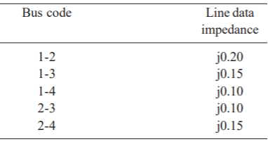
Q10) The line data of a 4-bus system is given below, obtain the YBUS.
A10)
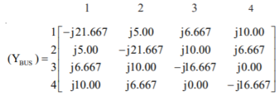
By inspection the YBUS is calculated. The values of the system are

The value of

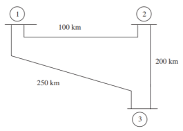
Q11) The single line-diagram of a network is shown below. The line reactance is 0.001 pu/km and shunt capacitance is 0.0016 pu km. Assemble the bus admittance matrix neglecting the line resistance.
A11)
The calculate line parameters are

The pu series admittance is

Shunt admittances at the nodes are
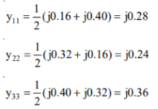
The elements of bus admittance matrix are calculated as


Then the bus admittance matrix is denoted by

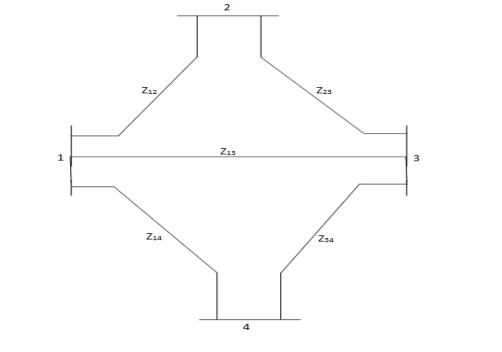
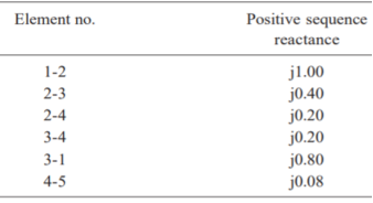
Q12) Form the YBus for the given network
A12)
The primitive admittances are

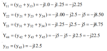
The diagonal elements are given by
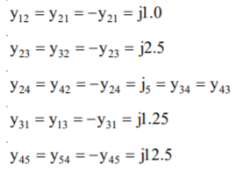
The off-diagonal elements are given by
The YBUS matrix is
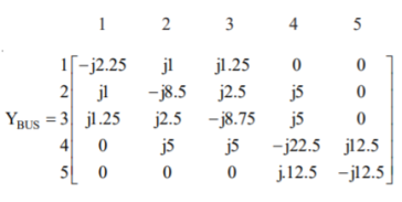
Q13) Find the bus admittance matrix of the following power system
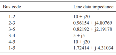
A13)
The primitive line admittances are obtained as
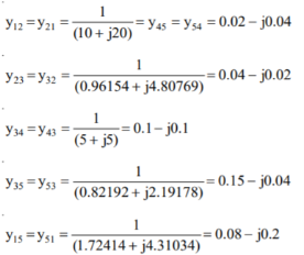
The diagonal elements are given by
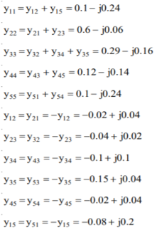
By direct inspection, the YBus is

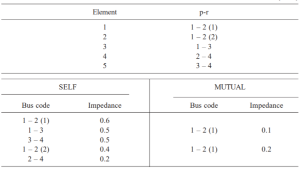
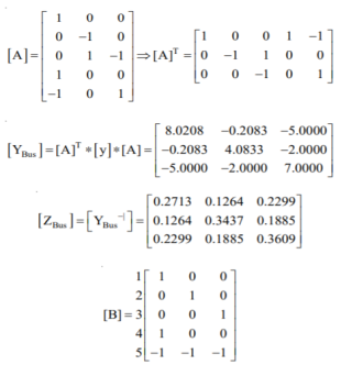
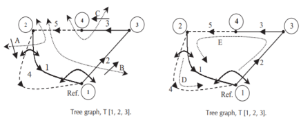
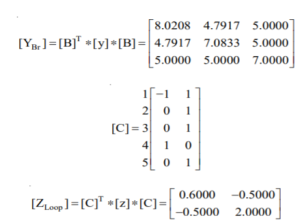
Q14) Form YBus, YBr and ZLoop by singular transformation for the network connections given below:
A14)
The power network is shown in Fig
Q15) Fig shows a 3–bus power system network. The line impedances are given below:
Line (bus to bus): 1 – 2 1 – 3 2 – 3(1) 2 – 3(2)
Impedance in pu: 0.02 + j0.1 0.02 + j0.1 0.05 + j0.25 0.05 + j0.3
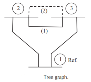
Formulate YBus for the following cases:
1. Assume that the line shown dotted between bus 2 and bus 3 i.e., line 2–3(2) is not present.
2. A new line 2–3(2) is connected and no mutual coupling with other lines.
3. When line 2–3(2) which has mutual impedance of (0.00 + j0.01) pu with line 2 – 3(1) is connected.
A15)
Case (1): By direct inspection:
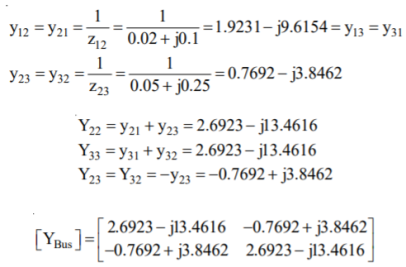
By singular transformation:
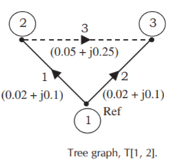
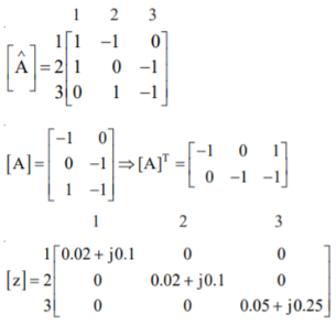
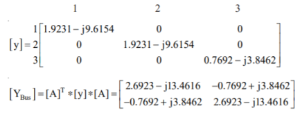
Case (2): By direct inspection:
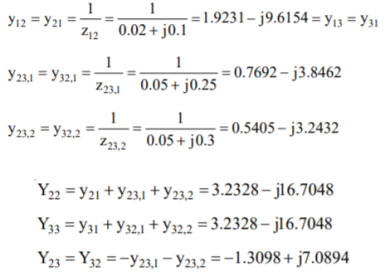

By singular transformation:

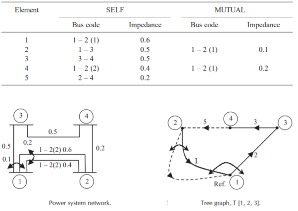
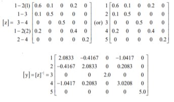
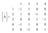
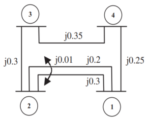
Q16) For the power system network shown in Figure, formulate YBus by singular transformation method. The self and mutual reactance in pu is indicated. Take bus (1) as reference.
A16)
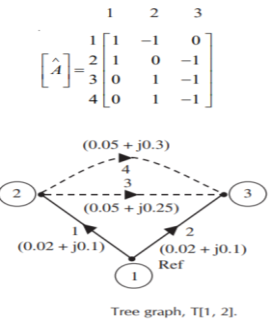
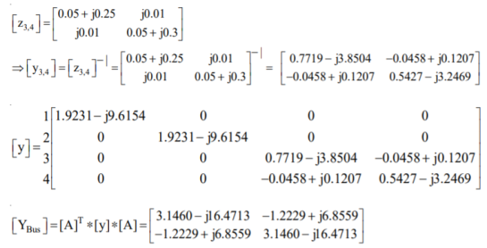
The oriented network is shown below and tree graph.
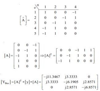
Q17) Form the YBus for the given network.
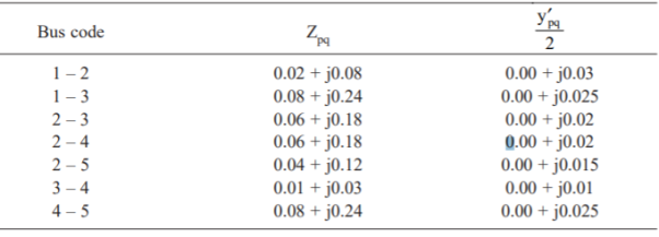
A17)
The admittance to ground is obtained by adding the admittances to ground at that bus
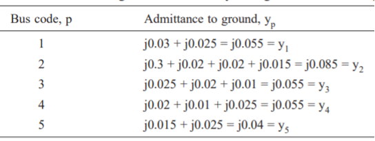

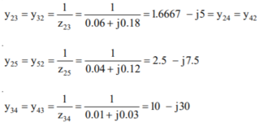
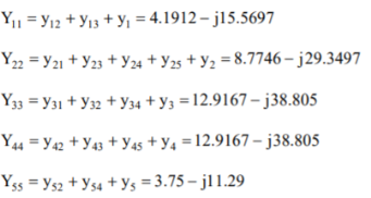
The diagonal elements are:
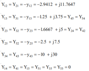
The off-diagonal elements are:
Therefore, the YBus is

Q18) Determine Y bus for the 3 bus system. The line series impedances are as follows:
Line (bus to bus) Impedance (pu)
1-2 0.06+i0.18
1-3 0.09+i0.09
2-3 0.08+i0.24
A18)
Neglect the shunt capacitances of the lines.


Y11 = Y12+Y13= 5-i15 Y22=Y12+Y23= 2.91-i8.75 Y33= Y13+Y23 = 4.58-i13.75
Y12= -Y12 = -1.66+i5 = Y21 Y23=Y32=-Y23= -1.25+i3.75 Y31=Y13=-Y31= 3.33+i10

Q19) Each line has a total shunt admittance of -i5. 0 pu. Determine the modified bus admittance matrix.
A19)
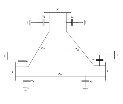
Yc+Yd=-I5.0 andYc=Yd
Ya+Yb=-i5.0 and Ya=Yb
Ye+Yf=-i5.0 and Ye=Yf
Ya = Yb = Yc = Yd = Ye = Yf = -i2.5
When we consider the effect of shunt admittances, only the diagonal elements in Ybus are modified.
Y11(new) = Y11(old) + Ya +Yc = 5-i15-i5 = 5-i20
Y22(new) = Y22(old) + Yd +Ye = 2.91- i8.75 -i5 = 2.91 -i13.5
Y33(new) = Y33(old) + Yf+Yb= 4.58 – i13.75 – i5 = 4.58 – i18.75

Q20) Determine Ybus for the 4-bus system shown. The line series impedances are as follows:
Line (bus to bus) Impedance (pu)
1-2 0.25+i1.0
1-3 0.20+i0.8
1-4 0.08+i1.2
2-3 0.20+i0.8
3-4 0.15+i0.6
Neglect shunt capacitances of the line.
A20)
