Unit - 4
Symmetrical Fault Analysis
Q1) A 3 phase 10000 kVA, 11 KV alternator has a sub transient reactance of 8℅. A three phase short circuit occurs at its terminals. Determine fault current and fault MVA.
A1)
Base current, 
Isc per unit =

Fault current, Isc =Isc per unit × IB
=12.5 × 525 =6562 A
Fault power =  × Isc× source voltage × 10-6 MVA
=  × 6562 × 11000 × 10-6 MVA
=125 MVA
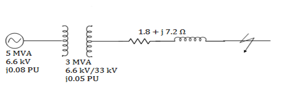
Q2) A 3 phase, 5 MVA, 6.6 kV alternator with a reactance of 8% is connected to a feeder of series impedance (0.12+i0.48) ohm/phase/km. The transformer is rated at 3 MVA, 6.6 kV /33 kV and has a reactance of 5%. Determine fault current supplied by the generator operating under no load with a voltage of 6.9kV, when a three phase symmetrical fault occurs at a point 15 km along the feeder.
A2)
Base MVA for complete system = 5MVA
Base kV = 33kV for feeder side
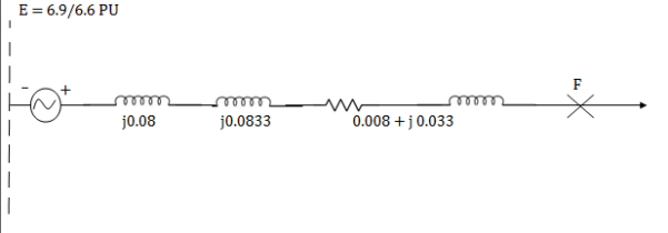
Xalternator (pu) = 0.08 pu
XT (New per unit) = XT (old pu) × ×
×
= 0.05 × (5/3) = i0.08333 pu
Impedance of feeder of length 15 km,
Zf = 15 × (0.12+i0.48) = 1.8 + i7.2 ohm = 7.42 < 76˚ ohm
Per unit reactance of feeder, Zfpu = Actual impedance ×
= (7.42<76) 
=0.034 pu< 76˚
=0.008 + i0.033 pu
Per unit fault current, Iscpu = 
Base current IB = 
Fault current = Iscpu × IB=(5.3285< -87.66) ×87.47 = 466 < -87.66˚A
Q3) Two 3 phase 11 kV generators of capacities 8MVA and 4MVA and sub transient reactances of 8% and 4% respectively operate in parallel. The generating station is connected to a transmission line of 200 km length through a step up Transformer of capacity 4 MVA and having percentage reactance of 3.5%. The resistance and reactance of the transmission line per km of its length are 0.025 ohm and 0.1 ohm respectively and it operates at 66 kV. Calculate the short circuit MVA for a phase to phase faults at the receiving end of the transmission line and at the sending end.
A3)
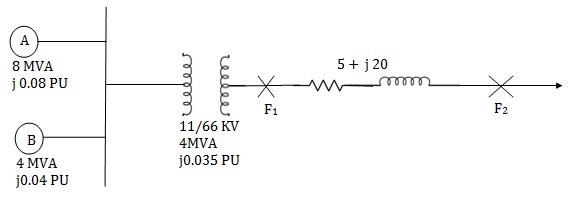
Base MVA for complete system = 8 MVA
Base kV for generator side = 11 kV
Thus, per unit reactance of generator A and B
XA(pu) = i0.08 pu
XB(pu) = 
Per unit reactance of transformer = 0.035 ×  = i0.07 pu
Impedance of transmission line = 200 × (0.025 + i0.1) = 5 + i20
Per unit impedance of transmission line = (5 + i20) × 
The single line reactance diagram can be drawn as-
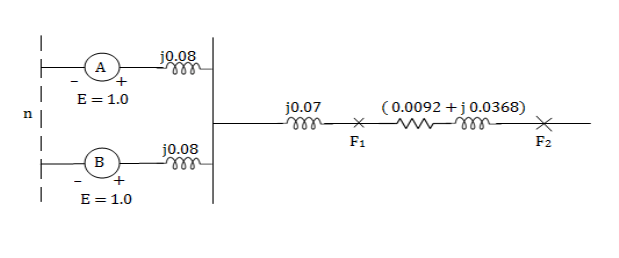
Reduced reactance diagram can be drawn

For a 3 phase fault at the sending end (F1) side of the transmission line, the total impedance upto the fault point
= i0.04 + i0.07 = i0.11
Fault MVA at F1 =  =
= 
For a 3 phase fault at the receiving end(F2) side of the transmission line, the total impedance upto the fault point = i0.04 +i0.07 + (0.0092 + i0.0368)
= 0.0092 + i0.1468
Fault MVA at F2 =  = 54.38 MVA
Q4) Two generators A and B are identical and rated 11kV, 10mVA and have a transient reactance of 20% at their own MVA base. Two transformers T1 and T2 are also identical and are rated 5mVA, 11166 kV and have a reactance of 5% at their own MVA base. The tie line is 100km and has a reactance of 0.1 ohm/km. A 3 phase fault occurs at a distance of 25km. From one end of the line when the system is on no load but at rated voltage. Determine fault MVA and fault current.
A4)

Let base MVA of the system be 10MVA, base KV of the generator side 11kV and for transmission circuit side 66kV.
For generator A, B

For transformer T1 and T2,

Per unit reactance of 25 km line =

Per unit reactance of 75 km line =

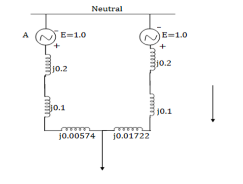
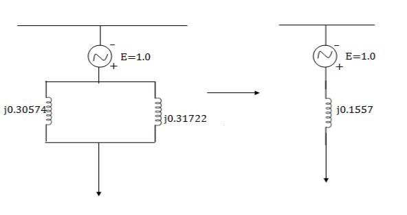
Xeqpu = i30574 || i0.31722
= i0.1557 pu
Fault MVA =
Fault current, Isc=
Q5) Determine the required MVA rating of the circuit breaker CB for the system shown in fig. Consider the grid as infinite bus. Choose 6MVA as base.
Transformer: 3 phase, 33111kV, 6MVA,
0.01+i0.08 pu impedance
Load: 3 phase, 11kV, 5800kVA, 0.8 lag, i0.2 pu impedance
Impedance of each feeder: 9+i18

A5)
Base MVA =6, Base kV for grid side is 33 kV and for load side is 11 kV.
Per unit impedance of transformer= 0.01 i0. 08 pu
Per unit impedance of feeder = 
Per unit impedance of load = 

Equivalent impedance upto fault point,
Zeqpu = [(0.04958+j0.09916)||(0.04958+j0.09916)]+(0.01+j0.08)
=(0.02479+j0.4958)+(0.01+j0.08)
=0.03479+j0.12958
=0.13417<74.97˚
Short circuit rating of CB = =
=  = 44.72MVA
Q6) A three phase 400V 75kW induction motor connected to infinite bus bar
i) 100kVA transformer
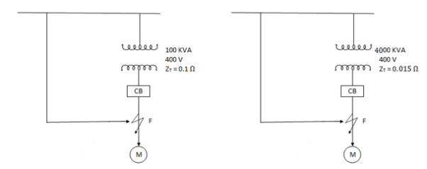
(ii) 4000 kVA transformer.
A6)
Full load motor current,

Assuming pf to be 0.8 lagging,
a) 
b) 
Thus, it us observed that as the system grows, the capability of supply of short circuit will be increased along with it.
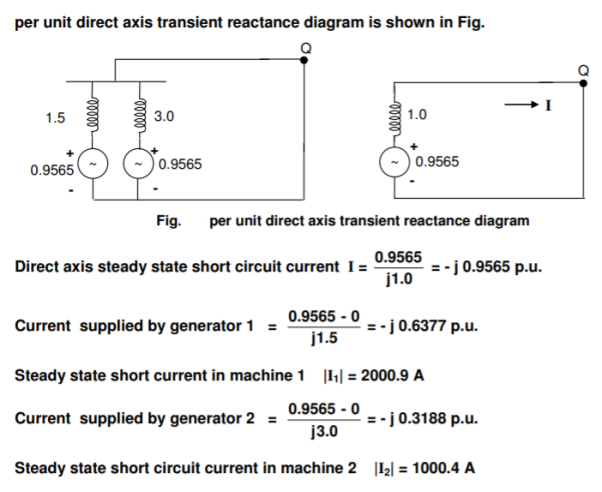
Q7) Two synchronous generators are connected in parallel at the low voltage side of a three-phase  -Y transformer as shown in Fig. Machine 1 is rated 50 MVA, 13.8 kV. Machine 2 is rated 25 MVA, 13.8 kV. Each generator has subtransient reactance, transient reactance and direct axis synchronous reactance of 25%, 40% and 100% respectively. The transformer is rated 75 MVA, 13.8
 /69Y with a reactance of 10%. Before the fault occurs, the voltage on high voltage side of the transformer is 66 kV. The transformer is unloaded and there is no circulating current between the generators?
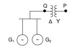
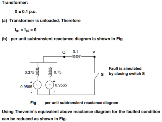
(a) Find the current supplied by the generators.
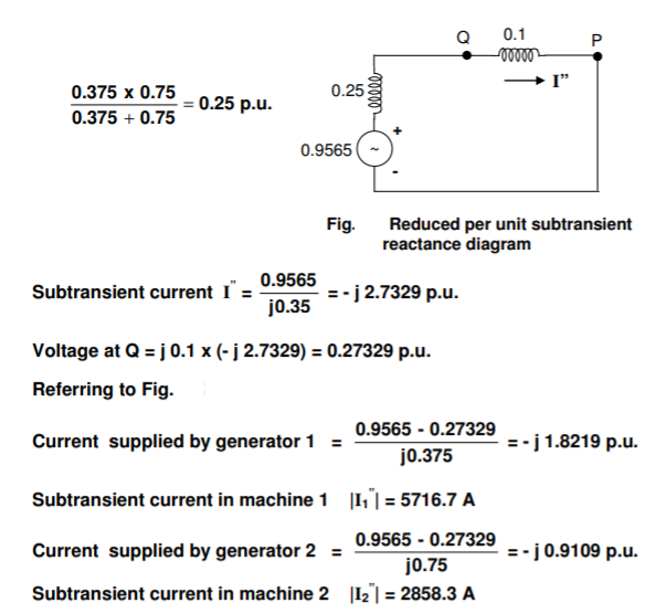
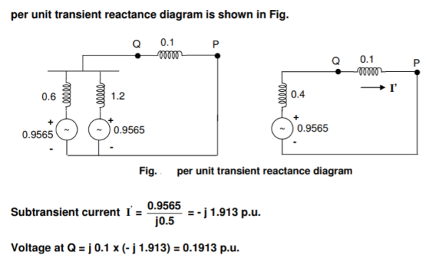
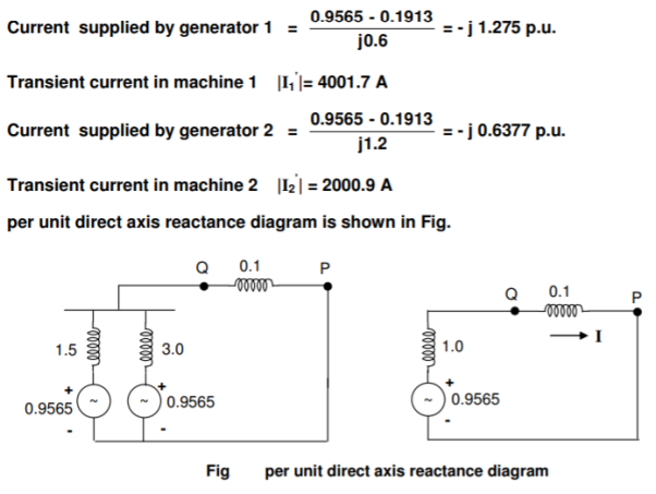
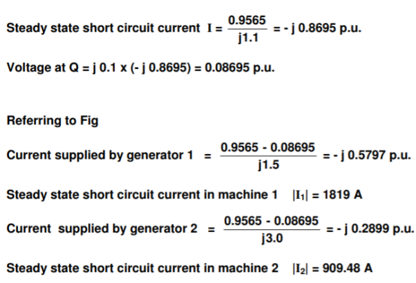
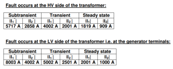
(b) A three-phase short circuit occurs at P. Determine the subtransient, transient and steady state short circuit current in each generator.
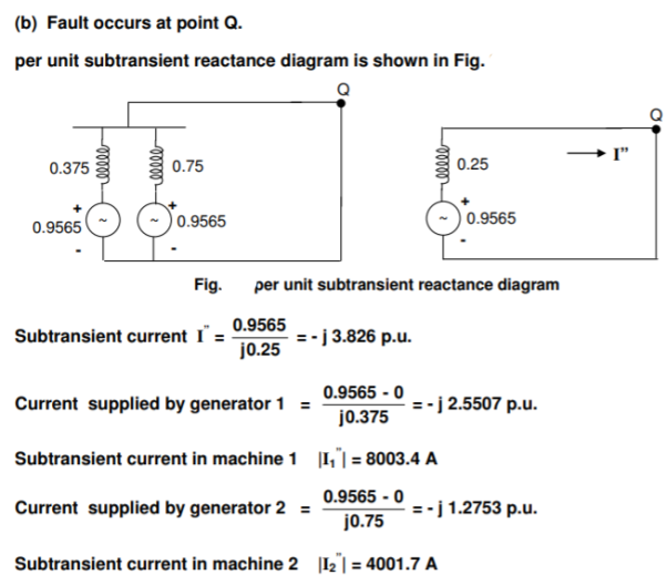
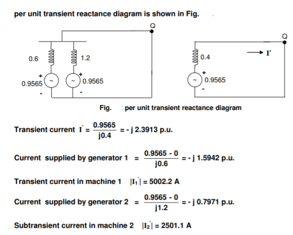
(c) A three-phase short circuit occurs at Q. Determine the subtransient, transient and steady state short circuit current in each generator. Select a base of 75 MVA and 69 kV in the high tension circuit.
A7)
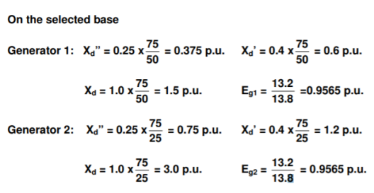
Base voltage at the low tension circuit = 13.8 kV
Prefault voltage at the LV side = (13.8/69 ) X 66 = 13.2 kV
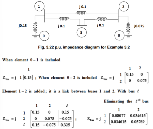
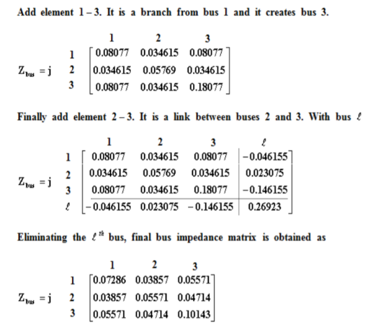
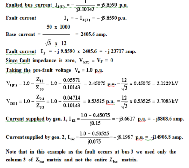
Q8) Consider the power system shown in Figure. The values marked are p.u. Impedances. The p.u. Reactances of the generator 1 and 2 are 0.15 and 0.075 respectively. Compute the bus impedance matrix of the generator – transmission network.

A8)
The ground bus is numbered as 0 and it is taken as reference bus. The p.u. Impedance diagram is shown in Figure.
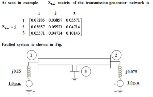
Q9) Consider a power system. The p.u impedances are on a base of 50MVA and 12kV. Symmetrical short circuit occurs at bus 3 with zero fault impedance. Using Zbus matrix determine the fault current, bus voltages and also the currents contributed by the generators?
A9)
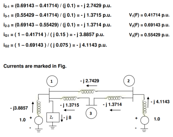
Q10) For the transmission-generator system shown in Fig.3.29, the bus impedance matrix is obtained as
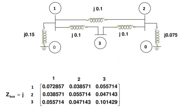
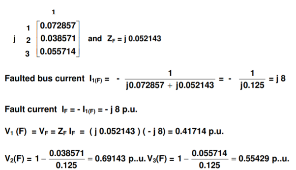
Symmetrical three phase fault with fault impedance j 0.052143 p.u. Occurs at bus 1. Find the p.u. Currents in all the elements and mark them on the single line diagram.
A10)
Fault occurs at bus 1 and we need the first column of ZBus, which is
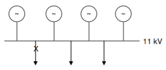
Q11) Fig. Shows four identical alternators in parallel. Each machine is rated for 25 MVA, 11 kV and has a subtransient reactance of 16 % on its rating. Compute the short circuit MVA when a three phase fault occurs at one of the outgoing feeders.
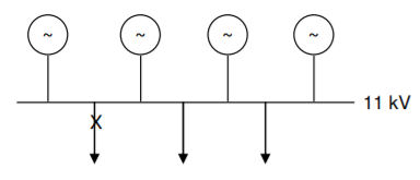
A11)
Fault is simulated by closing the switch shown in the p.u. Reactance diagram shown in Fig.(a). Its Thevenin’s equivalent is shown in Fig. (b).
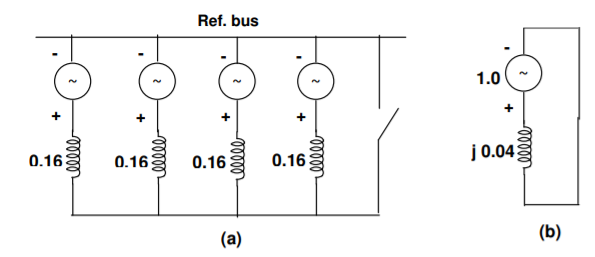
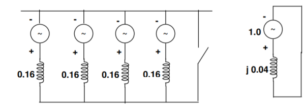
Fault current |IF| = 1/0.04 = 25p.u
Short circuit MVA = pre fault voltage in p.u. x fault current in p.u. x Base MVA = 1.0 x 25 x 25= 625
Q12) A 69-kV circuit breaker having a voltage range factor K of 1.21 and a continuous current rating of 1200 A has a rated short circuit current of 19000 A at the maximum rated voltage of 72.5 kV. Determine the maximum symmetrical interrupting capability of the breaker and explain its significance at lower operating voltage.
A12)
Nominal voltage = 69 kV
Voltage range factor K = 1.21
Continuous current rating = 1200 A
Rated short circuit current = 19000 A
Maximum rated voltage = 72.5 kV
The max. Symmetrical interrupting capability = K x rated short circuit current = 1.21 x 19000 = 22990 A
Since voltage range factor K = rated maximum voltage /lower limit of the range of operating voltage
Lower limit of operating voltage =72.5/1.21 =60kV
Operating voltage range is 72.5 kV to 60 kV. In this range, the symmetrical interrupting current may exceed the rated short circuit current of 19000 A, but it is limited to 22990 A.
For example at 66 kV, interrupting current = 72.5/66 x19000 = 20871A
Q13) In the generator system considered in question 11, it is decided to limit the fault level to 500 MVA. Find the external generator reactor need to be connected in series with each generator.
A13)
Short circuit MVA = prefault voltage in p.u. x fault current in p.u. x Base MVA
Fault current in p.u. =500/(1.0x25) =20
Since Fault current |IF| = 1 /Zth,
Thevenin’s impedance |Zth| = 1/20 = 0.05 p.u.
Thus, reactance in each generator branch X g + X ext = 4 x 0.05 = 0.2
Therefore, X ext, generator reactance needed = 0.2 – 0.16 = 0.04 p.u.
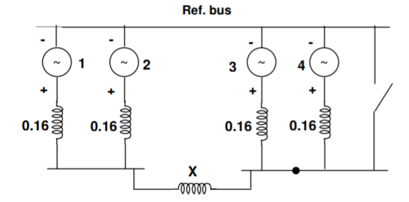
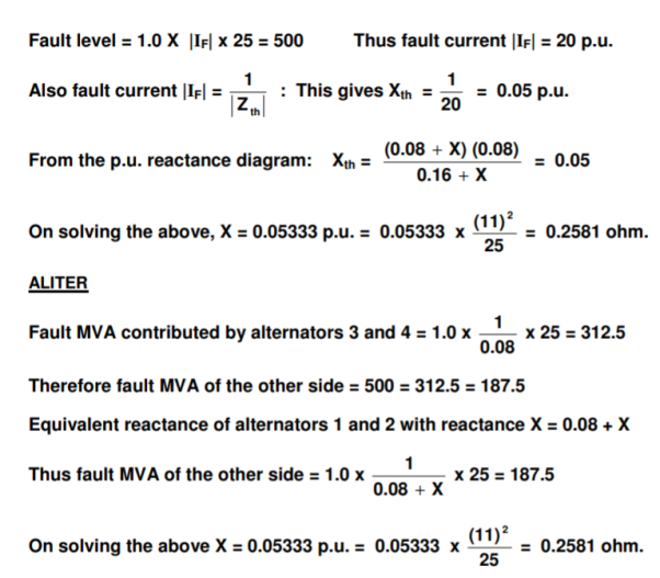
Q14) In the 4-alternator system shown in Fig. Find the reactance of the current limiting reactor X required to limit the fault level at F in a feeder to 500 MV.

A14)
Let the base MVA be 20 5 and the base voltage 11 kV. The p.u. Reactance diagram is shown below
Q15) A 33 MVA, 13.8 KV, 3-phase generator has a sub transient reactance of 0.5%. The generator supplies a motor through a step-up transformer - transmission line – step-down transformer arrangement. The motor has rated input of 25 MVA at 6.6 KV with 25% sub transient reactance. Draw the equivalent per unit impedance diagram by selecting 25 MVA (3), 6.6 KV (LL) as base values in the motor circuit, given the transformer and transmission line data as under: Step up transformer bank: three single phase units, connected  –Y, each rated 10 MVA,13.2/6.6 KV with 7.7 % leakage reactance and 0.5 % leakage resistance Transmission line: 75 KM long with a positive sequence reactance of 0.8 ohm/ KM and a resistance of 0.2 ohm/ KM; and Step down transformer bank: three single phase units, connected
  –Y, each rated 8.33 MVA, 110/3.98 KV with 8% leakage reactance and 0.8 % leakage resistance?
A15)
The one line diagram with the data is obtained as shown in figure

3-phase ratings of transformers: T1: 3(10) = 30 MVA, 13.2/ 66.43 KV = 13.2/ 115 KV, X = 0.077, R = 0.005 pu. T2: 3(8.33) = 25 MVA, 110/ 3.983 KV = 110/ 6.8936 KV, X = 0.08, R = 0.008 pu.
Selection of base quantities: 25 MVA, 6.6 KV in the motor circuit (Given);
The voltage bases in other sections are: 6.6 (110/6.8936) = 105.316 KV in the transmission line circuit and 105.316 (13.2/115) = 12.09 KV in the generator circuit.
Calculation of pu values:
Xm = j 0.25 pu;
Em = 1.000 pu.
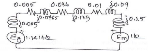
XG = j 0.005 (25/33) (13.8/12.09)2 = j 0.005 pu;
Eg = 13.8/12.09 = 1.41400 pu.
Zt1 = 0.005 + j 0.077 (25/30) (13.2/12.09)2 = 0.005 + j 0.0765 pu. (ref. To LV side)
Zt2 = 0.008 + j 0.08 (25/25) (110/105.316)2 = 0.0087 + j 0.0873 pu. (ref. To HV side)
Zline = 75 (0.2+j 0.8) (25/ 105.3162) = 0.0338 + j 0.1351 pu.
Thus, the pu reactance diagram can be drawn as shown in figure
Q16) A 30 MVA, 13.8 KV, 3-phase generator has a sub transient reactance of 15%. The generator supplies 2 motors through a step-up transformer - transmission line – stepdown transformer arrangement. The motors have rated inputs of 20 MVA and 10 MVA at 12.8 KV with 20% sub transient reactance each. The 3-phase transformers are rated at 35 MVA, 13.2 KV- /115 KV -Y with 10 % leakage reactance. The line reactance is 80 ohms. Draw the equivalent per unit reactance diagram by selecting the generator ratings as base values in the generator circuit.
A16)
The one line diagram with the data is obtained as shown in figure
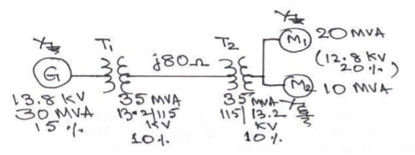
Selection of base quantities: 30 MVA, 13.8 KV in the generator circuit (Given);
The voltage bases in other sections are: 13.8 (115/13.2) = 120.23 KV in the transmission line circuit and 120.23 (13.26/115) = 13.8 KV in the motor circuit.
Calculation of pu values:
XG = j 0.15 pu.
Xm1 = j 0.2 (30/20) (12.8/13.8)2 = j 0.516 pu.
Xm2 = j 0.2 (30/10) (12.8/13.8)2 = j 0.2581 pu.
Xt1 =Xt2 = j 0.1 (30/35) (13.2/13.8)2 = j 0.0784 pu.
Xline = j 80 (30/120.232) = j 0.17 pu.
Eg = 1.0 00 pu;
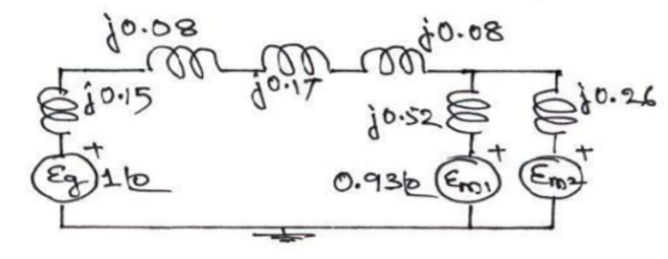
Em1 = Em2 = (6.6/6.31) = 0
Q17) What is quadrature axis synchronous reactance?
A17)
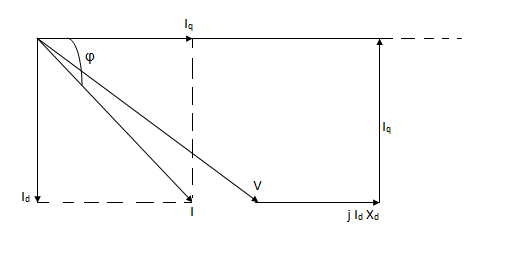
A quadrature axis is one whose magnetic effect is along the perpendicular to field pole axis. When the peak of armature mmf coincides with the quadrature axis., the reactance offered to the armature mmf is called quadrature axis reactance. In the above fig, the peak of armature mmf is along the perpendicular to the field poleaxis or direct axis.
Under this condition, the reactance offered by the two large air gap is maximum. For a given armature current, the armature mmf is constant and hence under this case the armature flux (FLUX =mmf/reluctance) is minimum.
The flux linkage per armature ampere is called quadrature axis or q-axis synchronous inductance Lq.
Xq = WLq= 2πfLq ohm
In case of salient pole synchronous machine, the air gap is non-uniform. Therefore, Xd> Xq. But due to uniform air gap in cylindrical pole synchronous machine, both direct and quadrature axis synchronous reactance are equal. i.e. Xd = Xq. In fact, due to presence of rotor slots along q-axis, Xq is slightly less than Xd for cylindrical pole synchronous machine.
In short circuit studies, only the direct axis reactances are involved.
Short circuit current in general feed through lines or transformers where the inductive reactance is quite large in comparison to resistance, making the power factor approach zero as currents go lagging and when the armature current is in quadrature (lagging) with the excitation voltage (or no load voltage) the entire armature mmf acts directly upon the magnetic paths through the salient pole field windin0gs.
Q18) Explain the analysis of unloaded alternator’s phase short circuit analysis?
A18)
In case of symmetrical short circuit i.e. short circuit on all the output terminals of a three phase alternator, the flux linkages in the armature circuit and the field circuit cannot change suddenly by the application of short circuit to the armature winding. For maintaining these flux linkages constant, large changes of current may take place in both of the windings when the short circuit occurs in order to keep their respective flux linkages constant.
In case of an RL series circuit, reactance X(wl) is constant quantity whereas in case of the synchronous generator, the reactance is not a constant one but it is a function of time. Thus, we have three reactance’s- direct axis sub transient reactance (Xd’’), direct axis transient reactance(X’d) and direct axis synchronous reactance(Xd).
Under normal no load condition of operation, there is no mmf due to armature reaction. When a sudden 3 phase short circuit occurs at the terminals of a synchronous generator, the current in the armature circuit increases suddenly to a large value (the symmetrical short circuit current is limited only by the leakage reactance of the machine) and since the resistance of the circuit is negligible as compared to its reactance, the current is highly lagging and the power factor is approximately zero. A sudden increase in armature current is accompanied by armature reaction. Since the air gap flux cannot change instantaneously, to counter the demagnetization of the armature short circuit current, currents appear in the field winding as well as in the damper winding in a direction to help the main flux. Thus, during initial part of the short circuit, the equivalent cut appears as
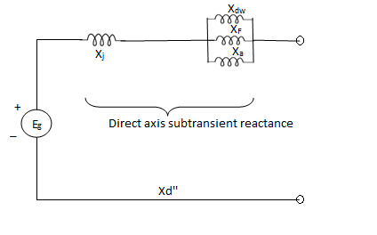
The effect of damper windings is to increase the initial value of short circuit current and to maintain a slightly increased current for three or four cycles after the short cut. When the main flux assumes the value it would have had if there has been no damper windings falls to zero after three or four cycles.
As the damper winding currents are first to die out, Xdw effectively becomes open circuited and at later stage Xf becomes open circuited.
The reactance represented by the machine in the initial period of the short circuit is called sub transient reactance Xd.
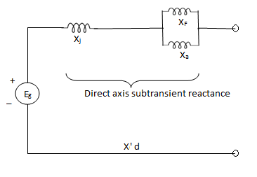

While the reactance effective after the damping winding currents have died out is called the transient reactance X'd.

The reactance under steady state short circuit conditions is the synchronous reactance of the machine.
X”d<X'd<Xd
Analysis of short circuit current in three phases of a synchronous generator
When a short circuit occurs across the terminals of a synchronous generator, the initial short circuit current is limited by the sub transient reactance for a few cycles, later on it is controlled by the transient reactance. Finally, the short circuit current settles down to the steady state short circuit value limited by the synchronous reactance of the machine. Depending upon the value of the phase voltage at the instant of short circuit will have least asymmetry in the short circuit waves.
Q19) Explain Sub-transient, Transient and steady state current and impedances
A19)
Sub transient current and impedance-
During the initial part of the short circuit on an unloaded alternator, the damper and field windings have transformer currents induced in them.
So that the circuit model includes the damper winding and field winding reactance in parallel with armature reactance.
The approximate circuit model during sub transient period of short circuit is shown below-
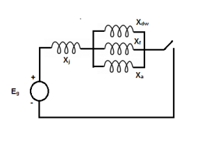
The sub transient reactance and current is given by-

 excluding dc component of current.
b) Transient current and impedance
After first three to four cycles of short circuit, the current in damper winding first die out and the damper winding reactance effectively becomes open circuited.
The approximate circuit model during transient period of short circuit is shown below-
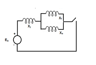

 excluding dc component of current.
c) Steady state current and impedance
In the last stage, when the main flux attain the original value before the short circuit occurs. The field winding reactance is cut out from the circuit. The armature current settles to steady state value.
The approximate circuit model during steady state period is shown below-
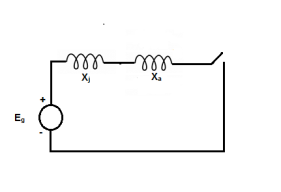
Xd = Xl + Xa

Q20) Write short note on Estimation of fault current without pre-fault current for simple power systems?
A20)
Limitations to fault current
An occurrence of a short circuit at any point in a system the short circuit current is limited by the impedance of the system up to the point of fault.
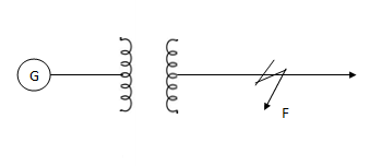
Also, the short circuit current depends on the size of the power system which supplies the short circuit current. Larger the supply source, greater will be the short circuit current. This is because of-
- Large kVA of the generating plant.
- Smaller impedance of the generating plant. Larger the size of the generating plant, smaller will be impedance.
- Smaller impedance between the generating station and the point of fault, larger the current carrying capacity of the line, the lower will be the impedance.
The analysis of symmetrical (L-L-L) faults includes determination of the voltage at any point in the power system network, the current in any branch and the value of reactance necessary to limit the fault current to any desired value. Such calculations provide the necessary data for selection of circuit breakers and design of protective scheme. The circuit breaker MVA breaking capacity is based on a three phase fault MVA.
The following assumptions are made during the short circuit analysis:
- Load currents are considered negligible as compared to fault currents.
- The transformer is represented by the reactance in series as Transformer resistance is quite low in comparison with its reactance.
- Shunt capacitances of the transmission lines are neglected
- System resistance is neglected and only inductive reactance of the system is taken into account. A transmission line is represented by series reactance and resistance.
- The EMFs of all the generators are assumed to be equal to 1<0° per unit.
- The effect of DC component is accounted for by using correction factors.
Network Reduction Technique
Because of the balanced nature of fault and the system, any condition which applies to 1 phase supply apply equally to the remaining two phases.
- Make out a single line diagram of the complete network indicating on each component its rating, voltage, resistance and reactance.
- Choose a common base kVA (or MVA) and convert all the resistances and reactance in per unit values as referred to common base kVA(or MVA).
- From single line diagram, draw single line reactance diagram showing 1 phase and neutral. In this diagram, write down reactance or impedances of the elements in per unit values.
- Reduce the reactance diagram by network reduction techniques keeping the identity of the point intact. Find the reactance of the system as seen from the fault Point (Thevenin reactance)
- Determine the fault current and fault MVA in per unit. Convert these per unit values to actual values.
Fault current and Fault MVA (steady state)
Isc per unit = 
Per unit fault MVA = √3 × per unit fault current × per unit source voltage
Or Fault MVA =  MVA lagging

