Unit 2
Satellite sub-systems
Q1) What is an attitude control system and how does it work?
A1) In this control technique, the satellite in its orbit is observed. This can be achieved by spinning the satellite or by three axes method. Both of these methods are discussed below in detail.
a) Spinning: The body of the satellite is rotated around its spin axis in this method and the rotation produces a gyroscopic force at 30-100rpm. This rotation makes the satellite point in the same direction and makes it stable. Such satellites are called spinners. A drum of cylindrical shape is placed inside a spinner which is covered with solar cells. The drum also consists of rockets and power systems. The drum has a communication subsystem on its top which is driven by an electric motor. The direction of rotation of the motor is opposite to the rotation of the satellite body. The satellite with such operations is called as de-spin.
b) Three-Axis Method: In this method, the orientation of the satellite is controlled by the axes. There is no need to rotate the main body of the satellite. There is a roll axis that is in the same direction as the satellite in the orbital plane. The yaw axis is directed towards the earth. The pitch axis is perpendicular to the orbital plane.
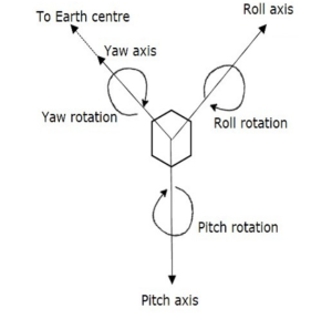
Fig: Three axis positions
The above-mentioned axes define the altitude of the satellite. This set of three-axis provides information about the orientation of the satellite with respect to reference axes. If there is a change in altitude of the satellite, then the angles between the respective axes will be changed.
There are two gas jets to provide rotation in both directions of the axes. The first gas jets make sure that the satellite has its motion in a particular direction. The second jet operates when the satellite reaches its desired position.
Q2) Explain the telemetry and monitoring system?
A2) The main function of satellite management is to control the orbit and attitude of the satellite, monitor the status of all sensors and subsystems on the satellite.
Telemetry and Monitoring System
The main aim of this system is to collect data from sensors that are present within the satellite and send them to controlling earth stations. There are many sensors on a satellite monitoring fuel level, temperature, voltage-current, etc. The telemetry system sends the sensor data, the status of each subsystem, the position of switches back to the earth.
The telemetry data are sent using PSK phase shift keying. At the earth station, there is a low data rate receiver as there are thousands of bits transmitted. The data rate is normally low so that narrow bandwidth is maintained and to have a high carrier to noise ratio.
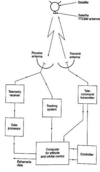
Fig: TTC&M system
Q3) What the power supply systems used in satellite?
A3) All communication satellites obtain their electrical power from the solar cells. The sun is a powerful source of energy. Solar cells do not convert all the incident energy into electrical energy only 20-25% is its efficiency. The three-axis stabilized satellites can make better use of solar cells. As the cells can be rotated to maintain the normal incidence of sunlight. The satellites must have batteries to provide backup during a solar eclipse as it occurs twice a year.
Q4) Derive the equation for the power received by the antenna?
A4) For a transmitter, without power Pt driving the lossless antenna with gain Gt the flus density at distance R will be
F = 
The product term PtGt is called Effective isotropic radiated power (EIRP). This EIRP is the combination of transmitting power and antenna gain in terms of an equivalent isotropic source having power PtGt. An ideal receiving antenna with aperture A will collect power
Pr= F*A
The effective aperture is given as Ae =  A
A
 = Aperture efficiency of the antenna (50-75% for parabolic and 90% for horn antennas)
Now the power received by a real antenna with effective aperture Ae is given as
Pr=  (1)
(1)
The gain of the antenna is given as
G = 
From 1 we have
Pr= 
The above equation is called a link equation. The term  is called path loss LP. The power received can also be written in dB as
Pr= EIRP +Gr-LP (2)
The above equation represents the ideal case with no losses in the link.
EIRP = 10log10(PtGt)
Gr = 10log10( )
)
LP = 10log10( )2
)2
But practically many other losses need to be taken count of such as attenuation by oxygen, water vapour, rain, or losses in antennas at the end of links. The above equation then changes to
Pr= EIRP +Gr-LP – La – Lta -Lra
Where:
La = attenuation in atmosphere
Lta =Losses due to transmitting antennas
Lra =Losses due to transmitting antennas
Q5) Explain and calculate the system noise temperature?
A5) Below shown is the figure of the simplified receiver which has an RF amplifier and single frequency conversion from the RF input to the IF output. These receivers are superheterodyne. The low noise amplifiers are the RF amplifiers that introduce noise in the receivers.
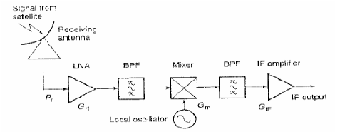
Fig: Simplified earth station receiver
The equivalent circuit for noise calculation is shown below. The noiseless blocks are used instead of noisy devices. These blocks have some gain and noise generators at the output also so that they produce the same values at the output as well.
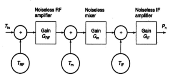
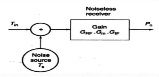
Fig: Equivalent noise source
The total noise power at the output of the receiver will be
Pn = GIF k TIF Bn + GIF Gm k Tm Bn + GIF Gm GRF k (TRF + Tin) Bn (3)
Where:
GIF Gm GRF = Gain of IF amplifier, mixer, and RF amplifier.
TIF Tm TRF = Equivalent noise temperature of IF amplifier, mixer, and RF amplifier.
The above equation can be also written as
Pn = GIF Gm GRF k Bn [TRF + Tin + Tm/GRF + TIF/ (Gm GRF)] (4)
Same noise power can be generated by a single noise source at the output.
Pn = GIF Gm GRF k Ts Bn (5)
Equating 4 and 5
Ts = [TRF + Tin + Tm/GRF + TIF/ (Gm GRF)] (6)
The equivalent noise model shows the output noise temperature of Tno
Tno = Tp (1-G1)
Noise Figure and Noise temperature
The noise figure is defined as
NF = (S/N)in/(S/N)out
The noise figure in terms of noise temperature is defined as
T = T0 (NF-1)
Q6) Explain the design of the satellite uplink?
A6) The satellite link in which the transmission takes place from the earth station to the satellite. The design of the uplink is easier than the downlink in many cases. The frequency-dependent losses like free space losses are calculated for uplink frequency.
The analysis of the uplink requires the calculation of the power level at the input to the transponder so that the uplink C/N ratio can be found. When the C/N ratio is specified for the transponder the calculation for the required power to be transmitted becomes easier.
For frequencies above 10GHzthere are disturbances in the form of fading. The rain causes to power level at the satellite to reduce below the permissible levels. Due to this, the C/N ratio at the transponder reduces, which in turn reduces the overall C/N ratio. The uplink power control can be used to overcome rain attenuation.
If the downlink attenuation is scaled it becomes easier to estimate for uplink. The uplink attenuation is given by
Aup = Adown x(fup/fdown)2
Due to rain, the link between earth and satellite is affected. The uplink C/N ratio in the transponder falls until UPC starts to operate.
Q7) Design parameters of downlink in satellite communication?
A7) The satellite needs a downlink and uplink for communication as we already know. During design, the C/N ratio is of major concern. The atmospheric conditions such as rain, eclipse affect the transmission. The basic parameters to be noted for the design of the downlink are
The link budgets are an important part of the design. They make the task easy as once a link budget is calculated it is easier to change any parameter and then again calculate the result. For each transponder, the link budget should be calculated and then repeated for individual links. There are four links for two-way communication systems. Link budgets are calculated when the link has a lower C/N ratio. The link budget depends on the following two parameters.
The calculation of carrier to noise ratio in satellite link is represented by
Pr= EIRP +Gr-LP – La – Lta -Lra
The noise power is given by
Pn = kTpBn
The receiving system noise is written as
N = k+Ts+Bn
The losses like feeder loss occur in connecting waveguides, filters, etc. There can be loss due to misalignment of the antenna called a pointing loss. As a first step in the loss calculations, the power loss resulting from the spreading of the signal in space must be determined.
In the C band and, more especially, the Ku band, rainfall is the most significant cause of signal fading. Rainfall results in attenuation of radio waves by scattering and by absorption of energy from the wave. Rain attenuation increases with increasing frequency and is worse in the Ku band compared with the C band. This produces depolarization of the wave; in effect, the wave becomes elliptically polarized. This is true for both linear and circular polarizations, and the effect seems to be much worse for circular polarization
Q8) Define the noise temperature and give the expression for noise power?
A8) In satellite communication, we have to deal with weak signals. As the signals are weak due to the distance and disturbances in space it is always required to keep the noise levels low. As there are active and passive elements used in the satellite system the noise temperature in the receiver can be known to get an idea of the thermal noise present. Any black body with a temperature Tp degree kelvin will produce electrical noise. The noise power is given by
Pn = kTpBn
k = Boltzmann constant (1.39 x 10⁻²³) J/K
Bn = noise bandwidth
The system noise temperature Ts is the noise temperature of the noise source which is present at the input of the noiseless receiver. This noiseless receiver will give the same noise power as the original receiver which will have noise from the antenna as well.
Q9) What is an orbit control system?
A9) As many other forces are acting in space that may deviate satellite from its orbit the orbit control system takes care of this. It helps to monitor and bring the satellite back to its position. The TTCM systems monitor this from earth stations. The LEO and MEO satellites also need AOC systems to maintain the correct orbit and attitude for continuous communication.
Q10) How is commanding done in TTC&M systems?
A10) To launch the satellite in proper orbit and to monitor its function in that orbit we need commanding subsystems. Whenever the attitude and orbit of a satellite are deviated these systems are responsible for adjusting them. It is responsible for turning ON / OFF of other subsystems present in the satellite-based on the data getting from telemetry and tracking subsystems.
The control words are converted to command words which are sent through TDM frames. The satellite checks for the correctness of these command words and then sends them to the earth station. The earth station again checks these command words if they are correct the execute signal is sent to the satellite.