Unit 4
Introduction to radar
Q1) Draw the block diagram and explain briefly the operation of radar?
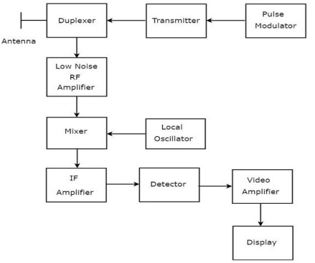
A1) The block diagram for radar is shown below. The function of each block is explained below.

Fig: Block Diagram
a) Transmitter: This consists of a radio frequency oscillator that is controlled by a modulator in such a way so that it produces periodic pulses of high power.
b) Antenna System: The output of the transmitter is fed to the antenna which radiates it efficiently in the desired direction. The antenna is directional and capable of rotating in azimuth or vertical plane. Mostly a single antenna is used for transmission and reception.
c) Duplexer: This controls the transmitting and receiving operation. When there is an interval in the pulse the duplexer connects the transmitter to the antenna and isolates the sensitive receiver from damage.
d) Timer: This controls the generation of pulse in the transmitter. The receiver and the indicator are in sync with the timer.
e) Indicator: The output is displayed when the receiver output is applied to the indicator.
f) Scanner: The scanning system rotates both the antenna and the indicator deflection coil.
g) Receiver: The radar receiver has high sensitivity ultra-high frequency having the lowest possible noise figure and having bandwidth adequate for handling the pulses involved.
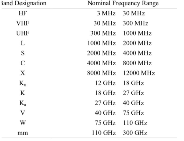
Q2) Write the various frequency ranges of radar?
A2) 
Q3) List the application of radar?
A3) The application of radar in various fields which are listed below.
1) In the military application for aiming guns and ships. For giving warning regarding approaching aircraft. For assisting fighter aircraft in locating and attacking enemy aircraft during night.
2) They have a major contribution to air traffic control. The aircraft are directed during bad weather and to detect and display the aircraft position at the airport terminal.
3) For proper routing of ships by monitoring sea ice.
4) The traffic police use radar surveillance for controlling the traffic and finding the speed of vehicles.
5) They also contribute to space observations like detecting the satellite and tracking it. For monitoring meteors.
Q4) Derive the radar equation?
A4) The range equation gives the relation between the transmitter, receiver, antenna, and target characteristics with the range of the radar. If the isotropic antenna receives the power PT from the transmitter.
Then power density at range R= 
The power density from the directional antenna will be = 
The target is described in terms of  which is the cross-sectional area.
The power density of the echo signal at radar will be = 

The power delivered to the receiver will be Pr = 
Due to insufficient power when the signal beyond a particular range cannot be detected is called its maximum range denoted by Rmax. The minimum detectable signal is the minimum power that the receiver can detect Smin.
Smin = 
Rmax = [ ]1/4
]1/4
Where:
Ae= effective area
GT = gain of the antenna
The GT for a circular paraboloid antenna is GT = 
Now the radar range equation will be
Rmax = [ ]1/4
]1/4
The above equation is the required equation.
Q5) Derive the expression for power of the interfering signal?
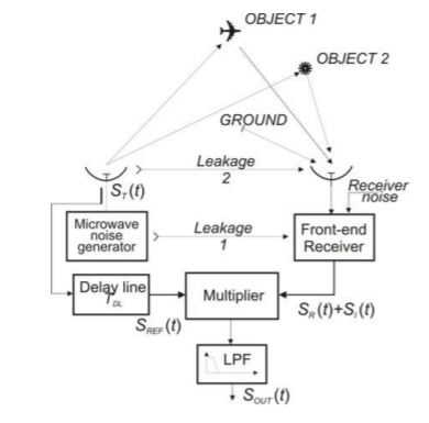
A5) Below shown is the functional diagram of noise radar with the existing signal types in real operating conditions. There is object 1 which transmits the desired signal SR(t) and other signals such as SI(t). The signals which are the radar transmitter noise signal are leakage 1, leakage2, and an interfering signal.

Fig: Functional diagram
For simplification, only two noise signals are considered in correlation with the reference signal SREF(t) which is the signal from object1, and SI(t) the interference signal. The power of the interfering noise signal is given by
PI = PLC +PLA +PR2 + PC + PN,R = PN,T +PN,R
PLA = receiving antenna power
PC = total power of radar
PN, R =power of self-noise
Q6) A noise generator using a diode is required to produce 15µV noise voltage in a receiver which has an input impedance of 75Ω (Purely resistive). The receiver has a noise power bandwidth of 200KHz to calculate the current through the diode.
A6)
Given Vn = 15µV
R = 75Ω
B = 200 KHz
Noise current flowing through 75Ω is
In = Vn /R = 15X10-6
= 0.2X10-6
= 0.2µa
Diode current –short noise current is given by
In2 = 2 (I +Io) qB
In2 = 2I X Q X B (neglecting Io)
(0.2 X 10⁻⁶) 2 = 2I X 1.6 X 10-19 X 200 X 103
I = 0.625 A = 625 µA
Q7) A receiver has a noise power bandwidth of 12KHz. A register that watches with the receiver input impedance is connected across the antenna terminals what is the noise power contributed by this register in the receiver bandwidth. Assume temperature to be 30ºC
A7)
Given: B = kHz; T = 30ºC = 30+ 273 = 303 K
Pn = KTB
= 1.38 X 10-23 X 303 X 12 X 103
= 5.01768 X 10⁻¹⁷ W
Q8) What are the probabilities of false alarm?
A8) A false alarm is noticed when the noise voltage is above the threshold voltage Vt. The probability can be defined by integrating the PDF
Pr (Vt <R<
 dR
dR
The average time crossing the threshold is a false alarm
Tfa= 
Tk = time between crossing the threshold.
Then the probability of false alarm is given by
Pfa = 1/Tfa 
 = Bandwidth
For  =
=  IF
IF
Tfa= 
The above equation is the required equation
Q9) Explain the coherent integration of radar pulses?
A9) Coherent Integration
The integrator used should have high accuracy otherwise there will be integration loss. If the accuracy of the integrator is high then SNR will be improved by the integration pulse np. The value of mth pulse is given by
ym(t) = s(t) +nm(t)
s(t) = radar return of interest
The value of the coherent integration of np pulse gives
z(t) =  =
=  = s(t) + =
The single pulse noise power is given by
 =
=  =
=  =
= 
From the above two equations, we see that SNR after coherent integration is improved by np.
Q10) What are the system losses in radar antenna?
A10) Some losses cannot be ignored like antenna beam shape loss, collapsing loss, and losses in microwave plumbing, etc. These are explained briefly below.
a) Plumbing Loss: There are some losses in the transmission line which are connected to the output of the transmitter to the antenna. There is less loss at low frequency in the transmission line. There can be losses in the connectors in the line and at the antenna, rotary joint if present. There is attenuation in the signal when it passes through the duplexer. The more isolation required from the duplexer on the transmission line the more is the insertion loss.
b) Beam shaped Loss: The antenna gain that appears in the radar equation is assumed to be a constant equal to the maximum value. But in reality, the train of pulses returned from a target with a scanning radar is modulated in amplitude by the shape of the antenna beam. The beam shaped loss is given as
Beam shaped loss= 
NB = number of pulses received
n= total number of pulses integrated
c) Limiting Loss: The probability of detection is lowered in the radar receiver due to limiting. Limiting results in a loss of only a fraction of a decibel for a large number of pulses integrated for a large value of limiting ratio.
d) Collapsing Loss: When the radar integrates the additional losses along with the S/N pulses then collapsing losses occur. It can occur in displays that collapse the range of information. If the square-law detector is used than the collapsing loss is given as
Li (m, n) = 
e) Operator Loss: The operator needs to be attentive all the time to notify or rectify an error if it occurs. The operator’s efficiency can be calculated by  0 = 0.7(Pd)2 where Pd is a single scan probability of detection. This is justified if the operator is alert and well trained. When the operator does not introduce loss into the system it is not easy to select a proper value to account for it.
f) Field Degradation: When the radar is operated under field conditions the performance deteriorates more than the expected value. The field degradation can occur if the radar is not supervised by any experienced personnel. To reduce field degradation there should be built-in automatic performance monitoring equipment. The radar characteristics that might be monitored include transmitted pulse, transmitter power, receiver noise level the shape of the spectrum, and decay time of the TR tube.
g) Other Losses: There is a complete loss of sensitivity for certain values of target velocity relative to the radar. These are called blind speeds. The straddling loss accounts for the loss in the S/N ratio for targets not at the centre of the range gate.