Unit-3
Theory of Vocoders
Q1) Explain PN codes?
A1)
- Pseudo-Noise (PN) also known Pseudo Random Binary Sequence (PRBS).
- A Pseudo-Noise code (PN-code) or Pseudo Random Noise Code (PRN code) is a spectrum which generated deterministically by random sequence.
- PN sequence is random occurance of 0’s and 1’s bit stream.
- Directly sequence spread spectrum (DS-SS) system is most popular sequence in DS-SS system bits of PN sequence is known as chips and inverse of its period is known as chip rate.
In frequency hopping spread spectrum (FH-SS) sequence, channel number are pseudo random sequences and hop rate are inverse of its period.
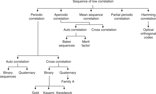
Fig. 1: Overview of PN sequence
- Properties
(i)Balance property:
Total no. Of 1’s is more than no. Of 0’s in maximum length sequence.
(ii)Run property 1’s and 0’s stream shows length sequence, every fraction relates some meaning.
Rum | Length |
1/2 | 1 |
1/4 | 2 |
1/8 | 3 |
(iii)Correlation property:
If compared sequences are found similar then it is autocorrelation.
If compared sequences are found mismatched then it is cross correlation.
Let (K) and y (K) are two sequences then correlation R (m) will be:
R (m)xy= x (k) y (k + m)
Correlation R (m) in pattern of digital bit sequence will be:
R (m)=
y1=P1 q1
y1=0 if P1 q1
y1=1 if P1 = q1
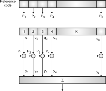
Fig. 2: Correlator
Fig5. Shows Pi is a sequence which shifts through K bit shift register. K is length of correlate. Output achieved by K XNOR gate after comparison.
(iv)Shift and add:
By using X-OR gate, shift sequence modulo-2 added to upshifted sequence.
PN sequence generation methodologies:
(i)Using shift register with feedback.
(ii)Series parallel method for high speed PN generation.
(iii)Avoiding zero state.
(iv)Barker sequence.
(v)Kasami sequence.
(vi)Gold sequence.
Q2) Explain spread spectrum technique?
A2)

Fig 3: General spread spectrum structure
- Spread spectrum is specially used for wireless communication signal spreading. Transmitted signals frequency varies deliberately.
- Frequency hopping and direct sequence are two popular spread spectrums.
In frequency hopping, signals are broadcast over any random series of frequency while in direct sequence each bit is in order of multiple bit of transmitting signal it uses chipping code.
Q3) Explain vocoders in detail?
A3) Vocoders are basically audio processor which will transmit speech signal in digital data. They are used for voice synthesis. They take two signals and then create the third signal by using the spectral information of those input signals. The vocoder is voice encoder and decoder.
The voice encoder is shown below having 15 BPF with bandwidth of 200Hz each. The output from the filter is fed to the rectifiers. The rectified signal which is dc is proportional to the amplitude of the ac signal at output.
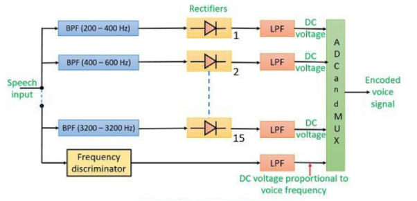
Fig 4 Voice encoder
The LPF generates dc voltage proportional to the voice frequency. The output from LPF is sampled, multiplexed and A/D converted. The voice decoder is shown below.
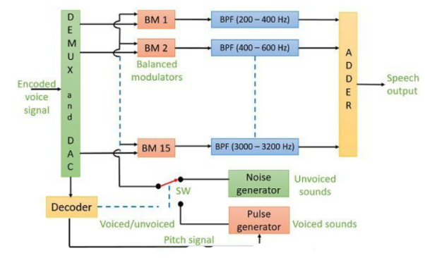
Fig 5 Voice Decoder
The signal is converted to its analog form by demux and D/A converters. The balanced modulators are used here who have carriers output of noise generator or pulse generator depending on position of the switch. When signal is unvoiced switch connects to noise generator. The adder produces the final output speech signal.
Q4) Explain FHSS System?
A4) Frequency Hoping Spread Spectrum (FHSS)
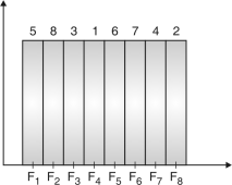
Fig 6: Channel assignment
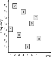
Fig.7: Channel use
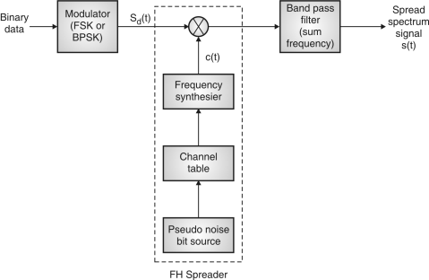
Fig.8: FHSS (Transmitter)
In FHSS, according to PN sequence RF carries frequency used to get change.
FHSS has two types
1.Fast hopped FHSS.
2.Slow hopped FHSS.
Hopping is done with faster rate compared to bit rate in fast hopped FHSS while slow rate compared to message bit rate in slow hopped FHSS.
FHSS systems rely on changes in RF carrier frequencies which turn into burst errors.
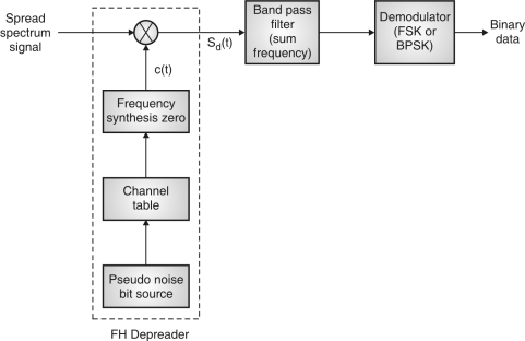
Fig.9: FHSS (Receiver)
Q5) What is time hopping?
A5) The signal is divided into time frames of M slots. Only one time slot is modulated when message is transmitted. The time hopping receiver is shown below. Let Tf = frame duration, k = number of message bits in one frame and Tf = k × tm, then the width of each time slot in a frame is Tf/M with BW of 2M.
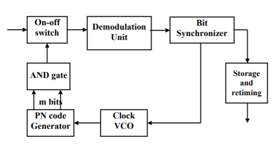
Fig 10 Time hopping receiver
The ON-OFF switch is driven by the PN generator so that proper switching takes place for the given time frame. The output from switch is demodulated. Each message burst is stored and re-timed to the original message rate in order to recover the information.
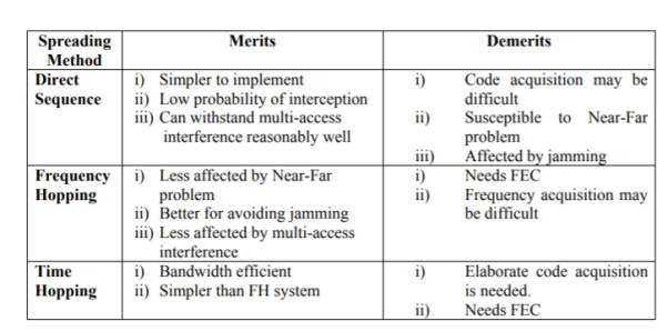
Q6) Compare FHSS, DHSS and Time hopping?
A6)
Q7) What are the multicarrier modulation techniques?
A7) In this type of modulation, the data stream is divided into small bits before transmission to modulate various carriers. The stream divided into bits has a lower data rate which modulates individual carriers. It was initially used in broadcasting systems.
There are various forms of MCM which were used in many fields such as OFDM was used for processing power in receivers. Later OFDM was used in wireless communication and Wi-Fi 802.11 etc.
Forms of Multicarrier Modulation System
i) OFDM: It is orthogonal frequency division multiplexing. It has multiple closely spaced carriers and due to the orthogonality between them mutual interference is avoided. It is most commonly used form of MCM.
Ii) GFDM: It is generalised frequency division multiplexing. The carriers used here are closed spaced and non-orthogonal. These carriers provide pulse shaping. They are widely used in machine-to-machine communications.
Iii) FBMC: It is called as filter bank multi carrier. This modulation uses isotropic transform algorithm within the DSP. The inter-carrier and inter-symbol interference are avoided by using this scheme.
Iv) SEFD: It is known as spectrally efficient FDM. It also uses multiple carriers but are closer than what are used in OFDM.
v) MC-CDMA: It is known as Multicarrier code division multiplexing. It is used to spread the signal over different subcarriers. Signals to different users are added linearly onto a multiplex of Multi-Carrier CDMA signals.
Q8) Hoe ISI occurs in the communication systems?
A8) When few symbols interfere with the subsequent signals ISI occurs which may distort the signal. The cause if ISI is due to multipath propagation and Non-linear frequency in channels. The blow figure shows the ISI in the signals.
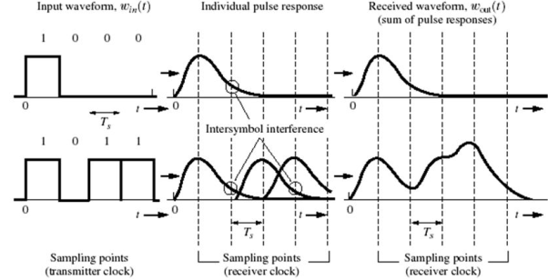
Fig 11 ISI on received Pulse
The Nyquist criterion to overcome ISI is called as Zero ISI. In this the pulse amplitude can be detected correctly irrespective of the signal spreading and overlapping.
The zero ISI pulse should satisfy the following condition
p(t) = 1 t=0
= 0 t=±Tb, ±2Tb, ±3Tb,……
When the pulse satisfies the given condition, it has zero ISI when received. The waveforms like square pulse of bit period Tb and triangular waveform of bit period <2Tb. The spectrum for these pulses is given below.
P(ω) =  for ω-
 <
<
= 0 for  >
>  +
+ 
= 1 for  <
<  +
+ 
 = frequency of bits
 = excess bandwidth
The pulse is shown below with the bandwidth
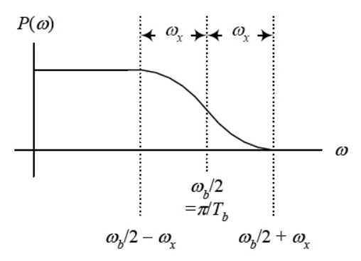
Fig 12 Spectrum of pulse
For  =0 the spectrum is rect function. For
  =
=  /2 spectrum is sinc function. The spectrum for which is shown below
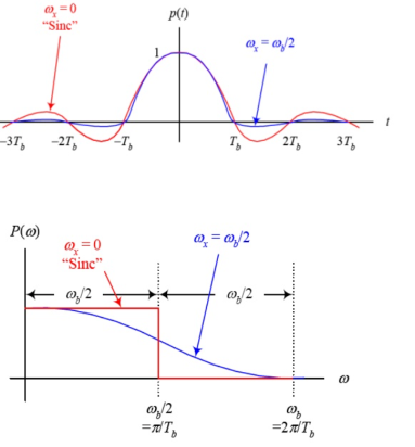
Fig 13 Spectrum of pulse
The roll-off factor r is given as r= =
= 
Q9) What is MIMO multiplexing?
A9) Spatial Multiplexing with MIMO
In this case each channel carries independent information which increases the data rate. It has some similarities with OFDM. Here each bit of data stream is multiplexed on three different channels as shown below. This increases the data rate. The diversity gain is zero and multiplexing gain is 3 as we are taking 3x3 MIMO.
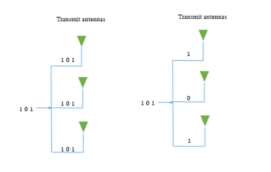
Fig 14 MIMO system with diversity MIMO with spatial multiplexing
When there are multiple antennas there are different propagation paths. SO, same data can be transmitted along different paths and this is called as spatial diversity.
When we try to improve the data rate by placing different portions of data on different propagation paths is spatial multiplexing.
Q10) Derive and explain adaptive equalizer?
A10) An equalizer is used to track time varying property of the mobile channel. Due to the randomness and time varying property of fading it is necessary to have an equalizer.
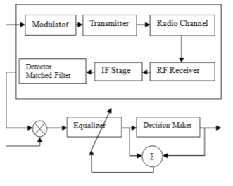
Fig 15 Adaptive Equalizer
Let s(t) be the original signal and signal f(t) is the combined response of channel, transmitter and IF/RF section of receiver. The signal at the input of the equalizer is
x(t) = s(t) f*(t)+nb(t)
The output of equalizer is
y(t) = x(t) heq(t)
Let g(t) be combined response of channel, transmitter and IF/RF section of receiver then above equation becomes
Y(t) = h(t) g(t) +nb(t)
 heq(t)
The impulse response of the equalizer transversal filter is given by
heq(t) = 
The output of equalizer needs to be equal to the original signal s(t).
y(t)= s(t) f*(t)
f*(t) heq(t)+nb(t)
 heq(t)
g(t)= f*(t) heq(t) =
 (t)
(t)
The following equation should be fulfilled
Heq(f)F*(-f) = 1
Where:
f*(t) = complex conjugate f(t)
heq(t) = equalizer impulse response
nb(t) = noise of baseband
Cn= complex coefficients of filter
Heq(f)= Fourier Transform of heq(t)