Unit 5
Frequency Modulation
Q1) Explain Basic Reactance Modulator.
A1)
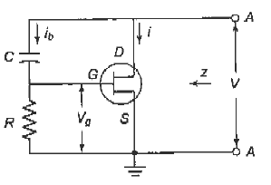
Fig.1: Basic reactance modulator
The above circuit is of a FET reactance modulator, which is a three terminal reactance that is connected across the tank circuit of the oscillator which is to be frequency-modulated.
It is made inductive or capacitive by a simple component change.
The value of the reactance is proportional to the transconductance of the device, which is dependent on the gate bias and its variations.
Here, an FET is used for simplicity only.
Identical reasoning would apply to a bipolar transistor or a vacuum tube, or indeed to any other amplifying device.
Q2) Explain Varactor Diode Modulator in detail.
A2)
A varactor diode is a semiconductor diode whose junction capacitance varies
linearly with the applied voltage when the diode is reverse-biased.
It is also used to produce frequency modulation.
It is certainly employed together with a reactance modulator, to provide automatic frequency correction for an FM transmitter.
The circuit below shows such a modulator.
Here, the diode has been back-biased to provide the junction capacitance effect, and it is also varied by the modulating voltage which is present in series.
The junction capacitance also varies, causing the oscillator frequency to change accordingly.
It is the simplest reactance modulator circuit, still it has the disadvantage of using a two-terminal device.
Its applications are limited and is often used for automatic frequency control and remote tuning.
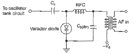
Fig.2: Varactor diode modulator
Q3) Explain Stabilized Reactance Modulator.
A3)
The oscillator on which a reactance modulator operates cannot be crystal- controlled, it must have the stability of a crystal oscillator if it is to be part of a commercial transmitter.
Hence, frequency stabilization of the reactance modulator is required, and it is similar to an automatic frequency control system.
The block diagram of a typical system is
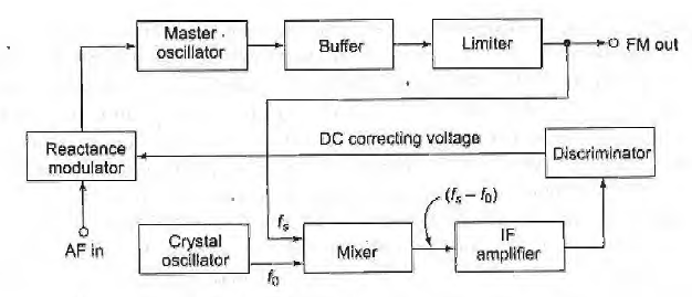
Fig.3: Stabilized Reactance modulator
The reactance modulator operates on the tank circuit of an LC oscillator.
It is isolated by a buffer, whose output moves from an amplitude limiter to power amplification by class C amplifiers.
A fraction of the output is taken from the limiter and fed to a mixer, which further receives the signal from a crystal oscillator.
The resulting difference signal, which has a frequency usually about one~ twentieth of the master oscillator frequency, is amplified and fed to a phase discriminator.
The output of the discriminator is connected to the reactance modulator providing a dc voltage to correct any drift in the average frequency of the master oscillator.
Q4) Explain Armstrong system.
A4)
A crystal oscillator cannot be successfully frequency-modulated, the direct modulators have the disadvantage of being based on an LC oscillator which is not stable enough for communications or broadcast purposes.
This requires stabilization of the reactance modulator with attendant circuit complexity. It is therefore possible to generate FM through phase modulation, where a crystal oscillator can be used.
lt is called the Armstrong system after its inventor, and it historically precedes the reactance modulator.
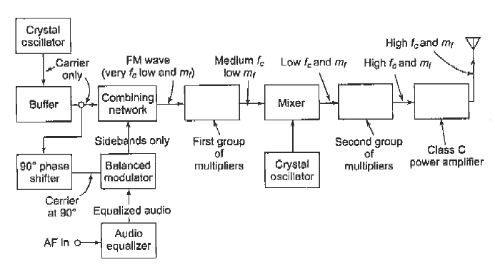
Fig.4: Armstrong Syatem
The system terminates at the output of the combining network; the remaining blocks are included to show how wideband FM might be obtained.
The effect of mixing on an FM signal is to change the center frequency only, whereas the effect of frequency multiplication is to multiply center frequency and deviation equally.
Q5) Explain Slope detection system.
A5)
- Slope detection: This is a very simple form of FM demodulation and it relies on the selectivity of the receiver itself to provide the demodulation. It is not particularly effective and is not used except when the receiver does not have an FM capability.
- It consists of a tuned circuit where the centre frequency is tuned to a frequency slightly offset from the carrier of the signal.
- Here, the frequency modulated signal sits on the slope of the response curve, giving rise to the name of FM slope detector.
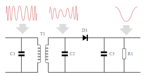
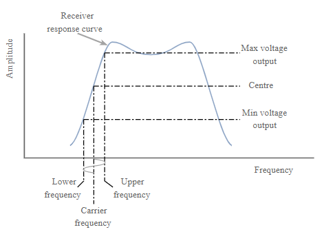
Fig 5: Slope detector
Q6) Write Advantages and disadvantages of FM slope detectors.
A6)
Advantages
- Simple - can be used to provide FM demodulation when only an AM detector is present.
- Enables FM to be detected without any additional circuitry.
Disadvantages
- Not linear as the output is dependent upon the curve of a filter.
- Not particularly effective as it requires the signal to be centred on the falling response of a filter. This means that the signal cannot be received at its maximum signal strength.
- Both frequency and amplitude variations are demodulated and this means that much higher levels of noise and interference are experienced.
Q7) Explain Ratio Detector.
A7)
- This type of detector was one that was widely used when discrete components were used in transistor radios.
- It offers a better level of amplitude modulation rejection.
- It provides a greater level of noise immunity as well.
- It also enables the FM detector to operate more effectively even with lower levels of limiting in the preceding IF stages of the receiver.
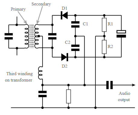
Fig.6: Ratio Detector
Advantages of the ratio FM detector
- Simple to construct using discrete components.
- Provides a good level of immunity to amplitude noise .
- Ratio detector has wider bandwidth than Foster Seeley discriminator.
Disadvantages of the FM ratio detector
- High cost of transformer.
- Only 50% output of the Foster-Seeley discriminator
- Higher distortion level than Foster-Seeley discriminator.
Q8) Explain Foster Seeley FM.
A8)
- In the days when radio used discrete components, this was the other main contender for the FM demodulator in radios.
- It operates using a phase difference between signals. For obtaining various signals a capacitor is connected at the primary side of the transformer and this is taken to the centre tap of the transformer. This gives a signal that is 90° out of phase.
- When an un-modulated carrier is applied at the centre frequency, both diodes conduct, to produce equal and opposite voltages across their respective load resistors.
- These voltages cancel each other out so that no voltage is present at the output.
- As the carrier moves off to one side of the centre frequency the balance condition is destroyed, and one diode conducts more than the other.
- This results in the voltage across one of the resistors being larger than the other, thus resulting voltage at the output corresponding to the modulation on the incoming signal.
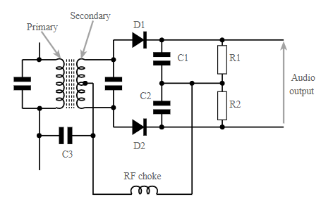
Fig.6: Foster Seeley
Advantages:
- Simple to construct using discrete components.
- Provides higher output than the ratio detector
- Provides a more linear output.
Disadvantages of Foster-Seeley FM discriminator:
- Does not easily lend itself to being incorporated within an integrated circuit.
- High cost of transformer.
- Narrower bandwidth than the ratio detector