Unit – 1
Introduction to signals
Q1) For the system with y(t)=x(-t), find whether the system is linear or not?
A1) To comment on linearity of system it should follow law of superposition. So. From model given below

Y(t)=ax1(-t)+bx2(-t)
Now from second model
Y(t)= ax1(-t)+bx2(-t)
Since, output from both the model is same so system is linear.
Q2) For y(t)=cos[x(t)], comment whether it is time invariant or not?
A2) From model 1

Y(t)=cos[x(t-t0)]
From model 2

Y(t)=cos[x(t-t0)]
Since, time delay or advance in the input signal produces the corresponding change in the output. Hence, it is time invariant.
Q3) For y(t)=x(t2), is the system causal or anti causal?
A3) y(t)= x(t2)
If the output for any time depends on the future than its not causal. So, Let t=1
Y(1)=x(1)
t=2
y(2)=x(4)
Since, it depends on future values, so it is anti-causal.
Q4) For y(t)=x(t)+2. Comment whether system has memory or memoryless?
A4) For t=1
Y(1)=x(1)+2
For t=2
Y(2)=x(2)+2
So, for any value of t the output depends only on present input. Hence, it is memoryless.
Q5) Find Vc(0) for given circuit
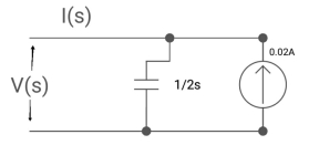
A5)
By Laplace transform

C=2F
CVc(0)=0.02A
Vc(0)=0.02/2=0.01A
Q6)
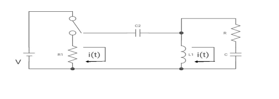
(a) switch is at before moving to position = at t= 0, at t= 0+, i1(t) is
(a) –V/2R (b) –V/R (c) – V/4R (d)0
A6)
i1(t) L.T I1(s)
i2(t) L.T I2(s)
Then express in form
[ I1(s)/I2(s)] [::] =[:]
Drawing the circuit at t = 0-
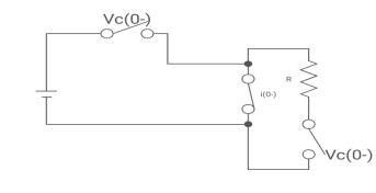
:. The capacitor is connected for long
Vc1(0-)= V
iL(0-) =0
Vc2(0-)=0
At t= 0+
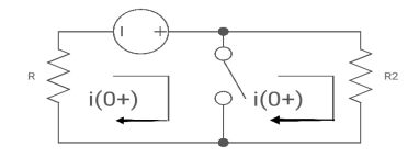
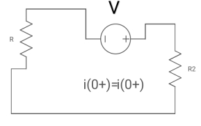
i1 (0+) = -V/2R
For t>0 the circuit is
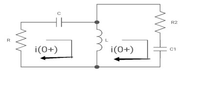
Apply KVL
-R i1(t) -1/c  dt -L
dt -L =0
=0
Also, we can deduce i1(t)- i2 (t) = iL(t)
-Ri1(t) -1/c  - L
- L = 0
= 0
-RI1(s)-[ -
- ]-L[sI1(s)-iL(0-)]=0
- RI1(s)- -
-  -s L I2(s)=0
 - s L I2(s)= -
  (1)
(1)
Again
-Ri2(t) ) -1/c  dt -L
dt -L =0
=0
-Ri1(t) -1/c  - L
- L = 0
= 0
Taking Laplace Transform
-RI2(s)- [ -
- ]- L[s IL(s)- iL(0-)]=0
-RI2(s)-  -
- Ls[ I1(s)- I2(s)]=0
 - s L I1(s)=0 (2)
Hence in matrix representation

 =
= 
Q7)
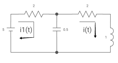
All initial conditions are zero i(t) L.T I(s) , then I(s)will be?
A7) Drawing Laplace circuit
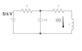
(2+5) 11 2/5
Zeq= 2(5+2)/S2+2S+2
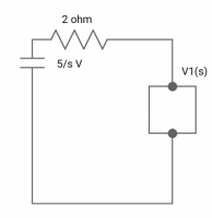
V1(s) = 5/S*2(S+2)/S2+2S+2
=10[(S+2)/S]/[2(2S+S2+2) +2(S+2)]
V1(s) = [5(S+2)/S]/S2+ 3S +4
I(s) = V1(s)/5+2 =(5/S)/(S2+3S+4)
Q8) Define even and odd signals?
A8)
1) A) The even signals are symmetrical about Y-axis. They lie in first and second quadrants.
x(-t)=x(t)
x[-n]=x[n]
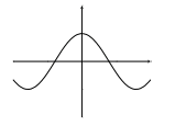
Fig: Even signal
The odd signals are symmetrical about origin. They lie in first and third quadrants.
x(-t)= -x(t)
x[-n]= -x[n]
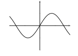
Fig: Odd signal
A signal having even and odd parts is mixed signal.
y(t)=sint + cost
y(t)=x0(t)+xe(t) (1)
From y(t) we can find odd and even parts by substituting t=-t in above equation
y(-t)=x0(-t)+xe(-t) (2)
y(-t)= -x0(t)+xe(t) (3)
Adding 1 and 3
 = xe(t)
 = x0(t)
x0(t)=
xe(t)=
Q9) Define energy and power in a signal?
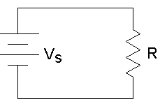
A9)
The power for above circuit with R=1Ω is given as
P= 
For R=1Ω
P=V2(t)=I2(t)
This is known as normalized power.
Total energy E= dt Joules
E=
Energy of periodic signal is always infinite.
Now calculating power P=
P= dt
dt
P= dt Watts
Power for Non-periodic signal is always zero.
Q10) Define linear and non-linear systems?
A10) Linear and Non-Linear system:
A system is said to be linear when it obeys law of superposition.
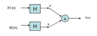
If we have two inputs x1(n) and x2(n), and output y(n). The operator ‘H’ is called linear operator if it satisfies the following condition.

In the above figure first the two inputs pass through an adder than through the operator. So, the equation after adder will be ax1(n)+bx2(n). Now final output equation after passing through operator is
Y(n)=H[ax1(n)+bx2(n)]=Hax1(n)+H bx2(n)
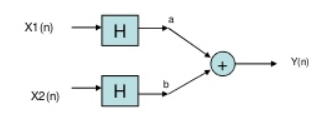
Now, in above figure the two inputs first pass through the operator and then through the summer. The equation at output is
Y(n)= Hax1(n)+H bx2(n)
The two output equations in both the systems are same. Hence, the system operator H is linear.
Non-Linear system: If the system does not obey law of superposition, it is said to be non-linear.
1) Time variant and Time Invariant system: A time delay or advance in the input signal produces the corresponding change in the output. Then the system is said to be time invariant.


Fig: Time-Invariant system
If the delay or advance in the system does not produce corresponding change in the output then it’s called as Time variant System.