Unit - 1
Introduction of Wireless Channel
Q1) Explain cellular system components?
A1) The cellular system components are listed below
i) Public Switched Telephone Network (PSTN): It has exchange area network, local networks and long-haul networks that are interconnected to other devices.
Ii) Mobile Telephone Switching Office (MTSO): It has MSC in it. It is the main center office. It has relay station for switching calls to PSTN.
Iii) Cell site with antenna system: It is the location of radio equipment which provides coverage within the cell. It consists of transmitters, receivers and antennas.
Iv) Mobile subscriber unit (MSU): It consists of transceiver which has the task of transmitting and also to receive radio transmission to and from cell site. The mobile telephone, portable and transportable are the types of MSUs.
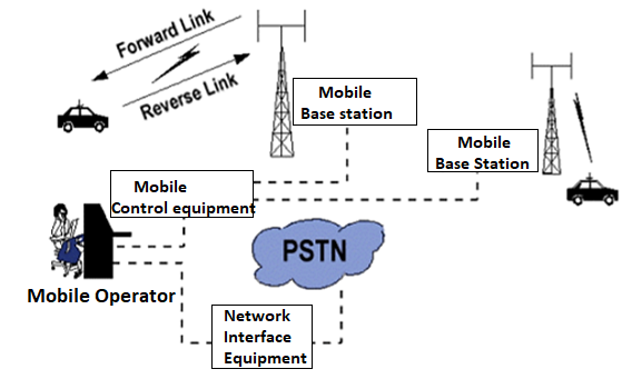
Fig 1 Cellular System Components
Q2) Explain the directivity of antenna?
A2) An antenna is a device that radiates equally in all directions. AN isotropic radiator is a small area considered. The gain is given as
DBi= Gain compared to isotropic radiator. It has gain 1db
DBd= gain compared to half wave dipole antenna.
The antenna which is not isotropic is directive. Directivity is
D= Maximum received power/Power received if the antenna was isotropic.
D= Pr(maximum)/Pr(isotropic)
Q3) Describe channel assignment strategies?
A3) In Cellular network, channel allocation schemes are required to allocate bandwidth and communication channels to base stations, access points and terminal equipment.
- The objective is to achieve maximum system spectral efficiency in bit/s/Hz/site by means of frequency reuse, but still assure a certain grade of service by avoiding co-channel interference and adjacent channel interference among nearby cells or networks that share the bandwidth.
- The basic concept being that a given geography is divided into polygons called cells.
- Each cell is allocated a portion of the total frequency spectrum. As users move into a given cell, they are then permitted to utilize the channel allocated to that cell. The virtue of the cellular system is that different cells can use the same channel given that the cells are separated by a minimum distance according to the system propagation characteristics; otherwise, intercellular or cochannel interference occurs.
The minimum distance necessary to reduce cochannel interference is called the reuse distance. The reuse distance is defined as the ratio of the distance, D, between cells that can use the same channel without causing interference and the cell radius, R. Note that R is the distance from the center of a cell to the outermost point of the cell in cases when the cells are not circular.
Q4) Draw and explain cellular infrastructure?
A4) The cellular system is replaced by large number of base stations (BS) which are hexagonal cells. They cover certain range of areas.
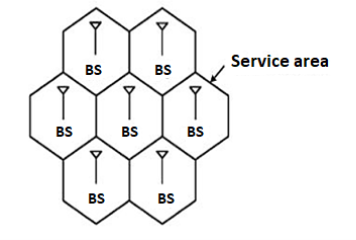
Fig 2 Cellular Structure
For having the communication in cellular structure, we need Mobile station (MS). In these types of structures, the MS communicates with the BS of cell. This is the location of MS in a BS cell. This BS acts as a gateway. For establishing connections, the MS needs to be in the range of the system. The figure below shows the same.
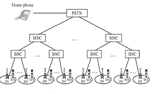
Fig 3 Cellular system infrastructure
Each base station controller (BSC) consists of MS and a BS. These BSC are then connected to the Mobile switching Centre (MSC). These MSC are then connected to a Public Switch Telephone Network (PSTN) and the Asynchronous Transfer Mode (ATM).
A base station consists of several base transceiver stations (BTS) and a BSC. The antenna and tower are the parts of BTS. The BTS system consists of towers and antennas.
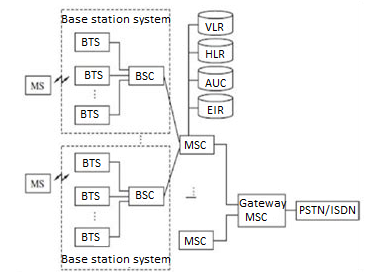
Fig 4 Generic block diagram of cell structure
The Home location register (HLR) is located at MSC. The MS is registered there only in the home location. The visitor location register (VLR) and HLR support mobility and helps to use one number i.e same number anywhere in world. The VLR has information about all MS.
The authentication and encryption are provided by Authentication centre (AUC). The database which provides identity and information about the mobile is equipment identity register (EIR).
Whenever there is a call it is directed to HLR where home MS is registered. This is then forwarded to VLR of MSC where MS is located currently.
Q5) What is frequency reuse?
A5)
It is process of combining analog and digital signal to send over shared medium.
It divides the capacity of communication channel into multiple channels
Multiplexing is divided into space division, frequency division and time division multiplexing.
Space Division Multiplexing
In wired medium, separate point to point conductors are used to each channel.
In wireless medium multiple elements of antennas are used such that it forms phased array antenna.
Multiple output, multiple input and single input multiple output are the examples of this.
Frequency Division Multiplexing
In these multiple signals are send in distinct frequency in single medium.
The signals are electrical.
Radio, television broadcasting are the examples of FDM.
The service provides can send several channels or signals continuously to all subscribers even the customer has single cable connection.
Time Division Multiplexing
In this for separation of data streams the time is used instead of frequency and space.
It consists of group of bits in sequence one after another.
Each sequence is associated with each receiver.
Carriers sense multiple access and multidrug are the eaxples of time division multiplexing.
Q6) What is Handoff strategy?
A6) If you’re a fan of the Olympics, I am sure you have watched plenty of track events – especially the exciting 400 and 800 meter relays. Four athletes run in each event and hand a baton off to the next athlete until the race is complete. Although the handoffs are usually done without mishap.
When a mobile moves into a different cell while a conversation is in progress, the MSC automatically transfers the call to a new channel belonging to the new base station. This handoff operation not only involves identifying a new base station, but also requires that the voice and control signals be allocated to channels associated with the new base station.
Three strategies have been proposed
- In mobile-controlled handoff(MCHO)
- In network-controlled handoff(NCHO)
- In mobile-assisted handoff(MAHO)
- In mobile-controlled handoff(MCHO)
The MS continuously monitors the signal of surrounding BSs and initiate the handoff process when some handoff criteria are met. MCHO is used in DECT
(Digital Enhanced Cordless Telecommunications)
2. In network-controlled handoff (NCHO)
The surroundings BSs measure the signal from the MS, 7 the network initiates the handoff process when some handoff criteria are met.
3. In mobile-assisted handoff (MAHO)
The network ask the MS to measure the signal from the surrounding BSs. The network makes the handoff decision based on report from the MS. MAHO is used in GSM & IS-95 CDMA
Inter-BS Handoff
In inter-BS handoff, the new & old BSs are connected to same MSC. Assume that the need for handoff is detected by the MS therefor the following actions are to be considered.
- The MS temporarily suspend conversation & initiates the handoff procedure by signalling on free channel in new BS. Then it resumes the conversation on the old BS. As in fig below.
- Upon receipt of the signal, the MCS transfer the encryption information to the selected idle channel of the new BS & set up the new conversation path to the MS through that channel.as in fig below
- After the MS has been transferred to the new BS, it signals the network and resume conversation using the new channel.
- Upon receipt of the handoff completion signal the network removes the bridge from the path and release resources associated with the old channel as in fig below.
This handoff procedure is used with mobile controlled handoff strategy. For network controlled handoff signalling messages are exchanged between the MS & old BS through the falling link. The whole process is completed as quickly as possible to ensure that new link
Q7) How a cell is sectorized in cellular communication explain?
A7) In this the frequency reuse is increased by reducing number of cells in cluster. The capacity is improved. The CCI is reduced by replacing omni-directional antenna by directional antenna.
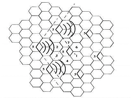
Fig 5 120o sectoring
Q8) Explain multipath fading?
A8)
- Multi path causes large and rapid fluctuations in a signal
- These fluctuations are not the same as the propagation path loss.
Multipath causes three major things in wireless communication
- Rapid changes in signal strength over a short distance or time.
- Random frequency modulation due to Doppler Shifts on different multipath signals.
- Time dispersion caused by multipath delays
- These are called “fading effects
Multipath propagation results in small-scale fading.
Q9) What are the types of channel assignment strategies?
A9)
There are two channel assignment strategies in cellular system.
A. Fixed channel assignment:
- In fixed channel assignment each cell is permanently allocated predetermined group of channels. Any call attempt within cell can only be served by unused channels in that particular cell.
- If all channels are occupied, the call is blocked and subscriber does not receive service.
- Borrowing technique where a cell is allowed to borrow channels from a neighbouring cell if all channels are already occupied is always used with this type of strategy. Mobile Base station (MSC) monitors the function of base station including borrowing ensuring that borrowing does not interfere with any call in progress in donor cell.
B. Dynamic channel assignment:
- In dynamic channel assignment strategy, voice channels are not allocated permanently.
- Entire pool of frequency channels lies with MSC and each time a call request is made, the serving base station requests a channel from the MSC. Switch then allocates a channel to the requested cell following a algorithm.
- MSC allocates frequency channels on dynamic basis if that frequency channel is not presently in use in the cell or any other cell which falls within the minimum restricted distance of frequency reuse to avoid co-channel interference.
- It reduces chances of blocking which increases trunking capacity of system as all available channels are accessible to all cells.
- In this MSC has to collect real time data on channel occupancy, traffic distribution, radio signal strength indication of all channels on continuous basis, thus increasing the computational load on MSC.
Q10) Explain general model of communication link?
A10) Mobile computing is an interaction between human and computer by which a computer is expected to be motivating during normal usage. Mobile computing involves software, hardware and mobile communication. Respectively, mobile software deals with the requirements of mobile applications. Also, hardware includes the components and devices which are needed for mobility. Communication issues include ad-hoc and infrastructure networks, protocols, communication properties, data encryption and concrete technologies.
Mobile Computing is a technology that allows transmission of data, voice and video via a computer or any other wireless enabled device without having to be connected to a fixed physical link.
In the last 10 years, the rise of mobile phones as well as laptops has dramatically, Increased the availability of mobile devices to businesses and home users. More recently, Smaller portable devices such as PDAs and especially embedded devices (e.g. Washing Machines, sensors) have slowly changed the way humans live and think of computers.
Mobile computing is associated with the mobility of hardware, data and software in computer applications. The study of this new area of computing has prompted the need to rethink carefully about the way in which mobile network and systems are conceived. Even though mobile and traditional distributed systems may appear to be closely related, there area number of factors that differentiate the two, especially in terms of type of device (fixed/mobile), network connection (permanent/intermittent) and execution context (static/dynamic)
A cellular or mobile phone is a long range portable electronic device for communication over long distance. Current Mobile Phones can support many latest services such as SMS, GPRS, MMS, email, packet switching, WAP, Bluetooth and many more. Most of the mobile phones connect to the cellular networks and which are further connected with the PSTN (Public switching telephone network). Besides mobile communications, there is a wide range of mobile products available such mobile scanners, mobile printers and mobile labellers.
Conceptually, computing can be seen as: USER ⇔ COMP.SYS ⇔ ENVIRONMENT
Q11) Explain the wifi wireless communication systems with its implementation?
A11)
- Wifi (also WiFi, Wi-fi or wifi), is a brand originally licensed by the Wi-Fi Alliance to describe the underlying technology of wireless local area networks (WLAN) based on the IEEE 802.11 specifications.
- Wi-Fi was intended to be used for mobile computing devices, such as laptops, in LANs, but is now often used for increasingly more applications, including Internet and VoIP phone access, gaming, and basic connectivity of consumer electronics such as televisions and DVD player
- The typical Wi-Fi setup contains one or more Access Points (APs) and one or more clients. An AP broadcasts its SSID (Service Set Identifier, "Network name") via packets that are called beacons, which are broadcast every 100 ms. The beacons are transmitted at 1 Mbit/s, and are of relatively short duration and therefore do not have a significant influence on performance. Since 1 Mbit/s is the lowest rate of Wi-Fi it assures that the client who receives the beacon can communicate at least 1 Mbit/s.
Q12) As application of cellular networks explain its application in satellite system?
A12) Satellites are used to transfer information from one place to another using communication satellite on Earth’s orbit. Satellite communication began in 1957 and the first artificial satellite launched was Sputnik I by the USSR. The satellite communication can be one way as well. In this case the transmission of signal from the transmitter of first earth satellite and the receiver of the second earth satellite is in one direction.
In two-way communication the information is exchanged between the two earth stations. There are two uplinks and two downlinks required to achieve two ways communication.
The main elements of communication satellite are
i) Uplink
Ii) Transponders
Iii) Downlink
The block diagram of satellite communication is shown below. A communication satellite is basically a R.F repeater.
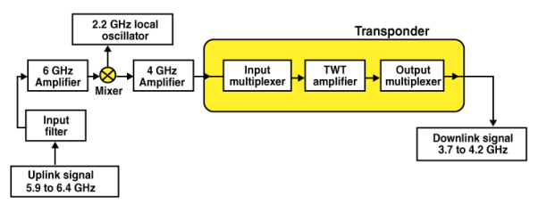
Fig 6 Block Diagram of Satellite Communication
The uplink frequencies used are of range 5.9GHz-6.4GHz these frequencies are converted to lower frequencies and amplified. The mixers and local oscillators are used to convert the higher frequency uplink signals to lower frequency signals. The com satellite receives this signal amplifies it and then transmits it so that there is no interference in the uplink and down link signals.
The transponders provide the medium for two-way communication. The downlink frequency used for transmission is from the range of 3.7GHz to 4.2GHz. The number of transponders per satellite depends upon the task which the satellite needs to do. For television broadcast two transponders are used in a satellite.
Advantages
The advantages of satellite communication are
- They are easy to install.
- The communication can be set up in every part of earth with the help of satellites.
- The network is controlled by the user.
- The elasticity of these circuits is excellent
Applications
The applications of satellite communication are
- Telephone
- Television
- Digital cinema
- Radio broadcasting
- Amateur radio
- Internet access
- Military
- Disaster Management
Q13) How radio astronomy and remote sensing are implemented with the help of cellular network?
A13)
- CORF has a substantial interest in this proceeding, as it represents the interests of the scientific users of the radio spectrum, including users of the RAS and the EESS bands. Both RAS and EESS observers perform extremely important, yet vulnerable research d by scientists to study our universe. It was through the use of radio astronomy that scientists discovered the first planets outside the solar system, circling a distant pulsar. Measurements of radio spectral line emission have identified and characterized the birth sites of stars in our own galaxy, and the complex distribution and evolution of galaxies in the universe. Radio astronomy measurements have discovered ripples in the cosmic microwave background, generated in the early universe, which later formed the stars and galaxies we know today.
- Observations of supernovas have allowed us to witness the creation and distribution of heavy elements essential to the formation of planets like Earth, and of life itself. The EESS is a critical and unique resource for monitoring Earth’s global atmospheric and surface state. Satellite-based microwave remote sensing represents the only practical method of obtaining uniform-quality atmospheric and surface data encompassing the most remote oceans as well as densely populated areas of Earth. EESS data have contributed substantially to the study of meteorology, atmospheric chemistry, oceanography, and global change.
- Currently, instruments operating in the EESS bands provide regular and reliable quantitative atmospheric, oceanic, and land measurements to support an extensive variety of scientific, commercial, and government (civil and military) data users. Applications of the data include aviation forecasts, hurricane and severe storm warning and tracking, seasonal and interannual climate forecasts, decadalscale monitoring of climate variability, medium-range forecasting, and studies of the ocean surface and internal structure, as well as many others. The emissions that radio astronomers study are extremely weak--a typical radio telescope receives only about one-trillionth of a watt from even the strongest cosmic source.
- Because radio astronomy receivers are designed to pick up such remarkably weak signals, such facilities are therefore particularly vulnerable to interference from spurious and out-of-band emissions from licensed and unlicensed users of neighboring bands, and those that produce harmonic emissions that fall into the RAS bands. Similarly, the emissions received by passive EESS radiometers in Earth orbit are weak by comparison with emissions from other services. In addition to the gains in scientific knowledge that result from radio astronomy and Earth sensing, CORF notes that such research enables technological developments that are of direct and tangible benefit to the public.
- For example, radio astronomy techniques have contributed significantly to major advances in the following areas: --Computerized tomography (CAT scans) as well as other technologies for studying and creating images of tissue inside the human body; --Abilities to forecast earthquakes by very-long-baseline interferometric (VLBI) measurements of fault motions; and --Use of VLBI techniques in the development of wireless telephone geographic location technologies, which can be used in connection with the Commission’s “E911” requirements.
- Continued development of new critical technologies enabled by passive scientific observation of the spectrum depends on scientists having continued access to interference-free spectrum. More directly, the underlying science undertaken by RAS and EESS observers cannot be performed without access to interference-free spectrum. Loss of such access constitutes a loss for the scientific and cultural heritage of all people, as well as for the practical civil and military applications arising from the information learned and the technologies developed.
Q14) Explain the working and application of Zigbee as it is the upper layer for control and sensors?
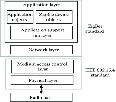
A14) Zigbee forms the upper layer for control and sensor applications. It is built above the IEEE 802.15.4. Zigbee can provide security and flexibility due to its design. It has now become an open alliance. Its setup was developed in 2002 by Zigbee Alliance.
Basic of Zigbee
As zigbee forms the upper layer it offers services like messaging. In security aspects and application of profile layers also this configuration can be implemented. IEEE 802.15.4 mainly focuses on security, control and monitoring where low levels of data are needed. The star, mesh and cluster tree network topologies are supported by ZigBee.
The star networks are simple networks. In this topology the outer nodes communicate with the centre node. The mesh topology consists of nodes placed according to the requirements. They provide a high degree of reliability. Here different stations are formed as relays to transmit messages. In case of interference at one section another can be used. The combination of mesh and star network is a cluster network.
Zigbee is designed for plow power consumption purposes. This increases the battery life and reduces the frequent maintenance cost.
Zigbee protocol features
- They support network topologies such as star, mesh and cluster.
- The design increases the battery life.
- Low latency
- It uses Direct Sequence Spread Spectrum (DSSS)
- 128-bit AES encryption for secure data connections
- It reduces collisions.
Application of Zigbee
Sensors, lighting controls, security and many more applications are all candidates for the new technology. They are also implemented in fields such as smart grid, lighting controls, high voltage AC control and in few medical devices.
Q15) What is paging and what are its types explain?
A15) While mobile devices perform updates according to their location update scheme, the network needs to be able to precisely determine the current cell location of a user to be able to route an incoming call. This requires the network to send a paging query to all cells where the mobile device may be located, to inform it of the incoming transmission. It is desirable to minimize the size of this paging area, to reduce the cost incurred on the network with each successive paging message. Ideally the paging area will be restricted to a known group of cells, such as with the currently implemented location area scheme. An optimum paging area size calculation involves a trade-off between location update cost and paging cost. This technique is used in many location- management schemes to reduce the location management costs incurred. The most commonly used paging schemes are summarized below. These have seen extensive use in real world telecommunications networks.
Simultaneous Paging
The simultaneous paging scheme, also known as blanket paging, is the mechanism used in current GSM network implementations. Here all cells in the users’ location area are paged simultaneously, to determine the location of the mobile device. This requires no additional knowledge of user location but may generate excessive amounts of paging traffic. Implementations of simultaneous paging favour networks with large cells and low user population and call rates. This scheme does not scale well to large networks with high numbers of users, necessitating the development of more advanced paging techniques.
Sequential Paging
Sequential paging avoids paging every cell within a location area by segmenting it into a number of paging areas, to be polled one-by-one. It is found in that the optimal paging mechanism, in terms of network utilization, is a sequential poll of every cell in the location area individually, in decreasing probability o f user residence. The individual delays incurred in this scheme may be unacceptable however, and hence it is suggested that paging areas are formed from a larger number of cells. The number of cells per paging area is a factor which needs to be optimized and may lead to excessive call delays, particularly in large networks. The order by which each area is paged is central to the performance of the sequential paging
Q16) Explain the block diagram of cordless system?
A16)
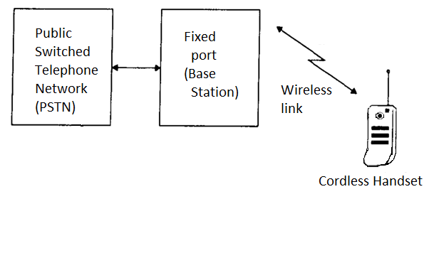
Fig 7 Block Diagram of Cordless System
- Cordless telephone systems are full duplex communication systems that use radio to connect a portable handset to a dedicated base station, which is then connected to a dedicated telephone line with a specific telephone number on the public switched telephone network.
- First generation cordless telephone systems in the 1980s had the portable unit communicating only to the dedicated base unit and only over distances of a few tens of meters. Early cordless telephones operated solely as extension telephones to a transceiver connected to a subscriber line on the PSTN and were primarily for in-home use. Second generation cordless telephones allow subscribers to use their handsets at outdoor locations within urban centers.
- Modern cordless telephones are sometimes combined with paging receivers so that a subscriber may first be paged and then respond to the page using the cordless telephone.
- Cordless telephone systems provide the user with limited range and mobility as it is usually not possible to maintain a call if the user travels outside the range of the base station.
- Typical second-generation base stations provide a coverage of up to a few hundreds of meters.
Q17) Explain the application and block diagram of first generation cellular system?
A17) First-generation analog cellular telephone
- First generation cellular and cordless telephone networks are based on analog circuit switching technology. The first 1Gmobile phone was introduced in the USA in 1980. FDMA was the multiple access technique used and worked mainly in the 800-900 MHz frequency bands. The 1Gmobile phone had only voice facility.
- Examples of 1G systems are AMPS (Advanced mobile phone service) and TACS (total access communication systems)
- The limitations of 1 Gare:
- Supports Speech only
- Low traffic capacity
- Unreliable handover
- Long call setup time
- Frequent call drops
- Inefficient bandwidth usage
- Poor battery life
- Poor voice quality
- Large size of handset
- Allowed users to make voice calls within a country only
- A typical example of a cellular telephone system is the Advance Mobile Phone Services (AMPS) system used in the United States. In 1971, Bell Telephone Laboratories in Murry Hill, New Jersey, proposed the cellular telephone concept as the Advanced Mobile Telephone System (AMPS). AMPS is a standard cellular telephone service (CTS) initially placed into operation on October 13, 1983, by Illinois Bell that incorporated several large cell areas to cover approximately 2100squaremilesin the Chicago area.
- Basically, all first generation systems use the transport architecture shown in the figure

Fig 8 Architecture
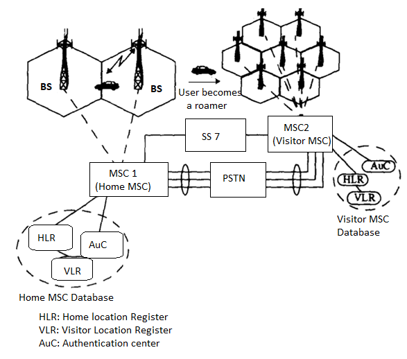
Fig 9 Block Diagram of First-Generation Cellular System
The block diagram of a first-generation cellular telephone network is shown in the figure. The system control for each market resides in the MSC which maintains all mobile related information and controls each mobile handoff. The MSC also performs the functions of network management, call handling and processing, billing and fraud detection within the market.
The MSC is interconnected with the PSTN via the landline trunked lines and a tandem switch. MSCs are connected with other MSCs via dedicated signaling channels for exchange of location, validation and call signaling information. First generation wireless systems provide analog speech and inefficient low-rate data transmission between the base station and the mobile user. The speech signals are usually digitized using a standard TDM format for transmission between the base station and the MSC and are always digitized for distribution from the MSC to the PSTN.
Q18) What are second generation cellular systems. Explain the advancements it has compared to first generation?
A18) Second-generation wireless telephone networks
- First-generation cellular telephone systems were designed primarily for a limited customer base, such as business customers and a limited number of affluent residential customers. The problems inherent with these cellular telephones were poor battery performance and channel unavailability. Improved batteries were also needed to reduce the size and cost of mobile units, especially those that were designed to be handheld. Weak signal strengths resulted in poor performance and ahigh rate of falsely initiated handoffs (false handoffs).
- It was determined that improved battery performance and higher signal quality were possible only by employing digital technologies.
- In the United States, the shortcomings of the first-generation cellular systems led to the development of several second-generation cellular telephone systems, such as narrowband AMPS (N-AMPS) and systems employing the IS-54, IS-136, and IS-95 standards.
- A second-generation standard, known as Global System for Mobile Communications (GSM), emerged in Europe. The U.S Standards of TDMA and CDMA also belong to this generation.
- Other second-generation wireless standard include, the British Cordless telephone standard CT2, Personal access Communication System (PACS) and the European standard for cordless and office telephony Digital European Cordless telephone (DECT).
- 2 G technology supports data, speech, fax, sms and WAP services.
- The architecture employed in second generation networks have reduced the computational burden on the MSC.
- GSM for example uses a base station controller (BSC) which allowed the data interface between the BSC and MSC to be standardized. This allows carriers to use different manufacturers for MSC and BSC components.
- All Second-generation systems use digital voice coding and digital modulation. The systems employ dedicated control channels within the air interface for simultaneously exchanging voice and control information between the subscriber, the base station and the MSC while the call is in progress.
- Second generation networks also provide dedicated voice and signaling trunks between MSCs and between each MSC and the PSTN.
- The first-generation systems were designed primarily for voice whereas the second-generation systems are specifically designed to provide paging, Fax and high data rate internet access.
- The network controlling structure is more distributed in second generation networks since mobile stations assume greater control functions.
- The handoff process is more mobile controlled and is known as Mobile assisted handoff (MAHO). The mobile units perform additional functions of received power reporting, adjacent base station scanning, data encoding and encryption.
- DECT (Digital European Cordless telephone) is an example of a second-generation cordless standard. It allows each cordless phone to communicate with any number of base stations. The base station with the greatest signal level is selected. The base stations have greater control in terms of switching, signaling and controlling handoffs.
- In general, second generation systems have been designed to reduce the computational and switching burden at the base station or MSC. They also provide more flexibility in the channel allocation scheme so that systems may be deployed rapidly and in a less coordinated manner.
- The limitations of 2Gare
- Low data rates ranging from 9.6 kbps to 28.8kbps
- Circuit switched network
- End systems are dedicated for the entire call duration
- Inefficient usage of bandwidth and resources
Q19) Explain the third and fourth generation wireless telephone networks?
A19) Third-generation wireless telephone networks
- The aim of third generation wireless networks is to provide a single set of standards that can meet a wide range of wireless applications and provide universal access throughout the world.
- In 3 G networks the distinctions between cordless telephones and cellular telephones disappear and a universal personal communicator or personal handset provides access to a variety of voice, data and video communication services.
- 3rd generation systems use the Broadband ISDN to provide access to information networks such as the internet and other private and public databases.
- 3 G networks carry all types of information like voice, data and video.
- They operate in densely populated and sparsely populated areas.
- They serve both stationary users and vehicular users travelling at high speeds.
- Packet radio communication is used in the 3 G networks
- Personal communication System (PCS), International Mobile Telecommunication (IMT-2000) and Universal Mobile telecommunication System (UMTS) are examples of 3G wireless networks. UMTS is also known as W-CDMA (Wideband CDMA)
Fourth-generation wireless telephone networks
- 4th-generation networks emerged as a data-optimized technology with the promise of speed improvements up to 10-fold over existing 3G technologies.
- It is basically the extension in the 3G technology with more bandwidth and services offers in the 3G.
- The expectation for the 4G technology is basically the high-quality audio/video streaming over end to end Internet Protocol. The transmission rates of 4G will be up to 20Mbps higher than that of3G.
- The first two commercially available technologies billed as 4G were the WiMAX standard and the LTE standard. LTE – Advanced is the newest version of LTE.
- One of the main ways in which 4G differed technologically from 3G was in its elimination of circuit switching, instead employing an all-IP network. 4G utilizes packet switching over internet, LAN or WAN networks via VoIP.
- 4G technology is meant to provide what is known as “ultra-broadband” access for mobile devices. It is set to deliver 100 Mbps to a roaming mobile device and up to 1 Gbps to a stationary device.
- 4G will bring the perfect real-world wireless inter networking called World Wide Wireless Web.
- 4 G allows for video conferencing, streaming picture-perfect video for telemetric applications
- OFDMA multi-carrier transmission methods, frequency-domain equalization (FDE) methods, MIMO (Multiple Input Multiple Output) and Turbo Code techniques are used in 4 G networks.
- Peak data rates for 4G networks must be close to 100 megabit per second for a user on a highly mobile network and 1 gigabit per second for a user with local wireless access or a nomadic connection.
- True 4G must also be able to offer smooth hand overs across differing networks without data loss and provide high quality of service for next-gen media.
- One of the most important aspects of 4G technology is the elimination of parallel circuit-switched and packet-switched network nodes using Internet Protocol version 6 (IPv6). The currently used standard, IPv4, has a finite limitation on the number of IP addresses that can be assigned to devices
Q20) Compare various wireless systems?
A20)
Service | Coverage Range | Required Infra-structure | Complexity | Hardware cost | Carrier Frequency | Functionality |
TV Remote control | Low
| Low | Low | Low | Infra-red | Transmitter |
Garage Door opener | Low | Low | Low | Low | <100 MHz | Transmitter
|
Paging system | High | High | Low | Low | <1 GHz | Receiver |
Cordless phone | Low | Low | Moderate | Low | <100 MHz | Transceiver
|
Cellular phone | High | High | High | Moderate | 1< GHz | Transceiver
|