Unit - 1
Introduction To Computer Networks
Q1) What is LAN define?
A1)
Local Area Network (LAN)
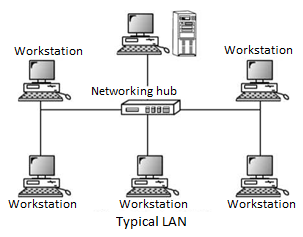
Networks used to interconnect computers in a single room, rooms within a building or buildings on one site are called Local Area Network (LAN). LAN transmits data with a speed of several megabits per second (106 bits per second). The transmission medium is normally coaxial cables. LAN links computers, i.e., software and hardware, in the same area for the purpose of sharing information. Usually, LAN links computers within a limited geographical area because they must be connected by a cable, which is quite expensive. People working in LAN get more capabilities in data processing, work processing and other information exchange compared to stand-alone computers. Because of this information exchange, most of the business and government organizations are using LAN.
Major Characteristics of LAN
Every computer has the potential to communicate with any other computers of the network. High degree of interconnection between computers. Easy physical connection of computers in a network. Inexpensive medium of data transmission. High data transmission rate.
Q2) Difference between LAN and WAN?
A2)
LAN is restricted to limited geographical area of few kilometers. But WAN covers great distance and operate nationwide or even worldwide.
In LAN, the computer terminals and peripheral devices are connected with wires and coaxial cables. In WAN there is no physical connection. Communication is done through telephone lines and satellite links.
Cost of data transmission in LAN is less because the transmission medium is owned by a single organization. In case of WAN the cost of data transmission is very high because the transmission mediums used are wired, either telephone lines or satellite links.
The speed of data transmission is much higher in LAN than in WAN. The transmission speed in LAN varies from 0.1 to 100 megabits per second. In case of WAN the speed ranges from 1800 to 9600 bits per second (bps). Few data transmission errors occur in LAN compared to WAN. It is because in LAN the distance covered is negligible.
Q3) Explain DQDB?
A3)
A Metropolitan Area Network (MAN) is a bigger version of a Local Area Network (LAN) and usually uses similar technology.
A MAN can cover a group of corporate offices or a town or city, and can be either privately or publicly owned. A MAN can support both data and voice, and may be related to the local cable television network (CATV).
A MAN employs one or two cables, and does not contain switching elements, which simplifies the design.
A standard has been adopted for MANs called Distributed Queue Dual Bus (DQDB) and is defined by IEEE 802.6.
DQDB consists of two unidirectional buses (cables) to which all of the computers on the network are connected.
Each bus has a head-end that initiates transmission activity.
• In the following diagram, traffic that is intended for a computer to the right of the source computer uses the upper bus, while traffic intended for a computer to the left uses the lower bus.
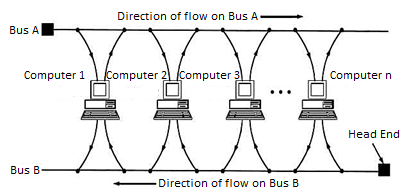
Fig. Typical MAN network (also known as 802.6 DQDB network)
Q4) Write Comparison between LAN, MAN, WAN?
A4)
Comparison between LAN, MAN, WAN
Basis of Comparison | LAN | MAN | WAN |
Expands to | Local Area Network | Metropolitan Area Network | Wide Area Network |
Meaning | A network that connects a group of computers in a small geographical area. | It covers relatively large region such as cities, towns. | It spans large locality and Connects countries together. Example Internet. |
Ownership of Network | Private | Private or Public | Private or Public |
Design and maintenance | Easy | Difficult | Difficult |
Propagation Delay | Short | Moderate | Long |
Speed | High | Moderate | Low |
Fault Tolerance | More Tolerant | Less Tolerant | Less Tolerant |
Congestion | Less | More | More |
Used for | College, School, Hospital. | Small towns, City. | Country/Continent. |
Q5) Define client- server Architecture?
A5)
In a client/server network, a number of network clients or workstations request resources or services from the network. One or more network servers manage and provide these resources or services. The clients are computers that depend on the server for data and software. Network servers are also referred to as computer servers, or simply servers. Sometimes a server is described in terms of the specific service it provides, such as e- mail server, print server or storage server. Some servers, however, can provide all these services.
Servers are typically computers with more processing speed, memory and hard disk space than a regular desktop computer. The network servers run their own operating system that manages the various network tasks as well as services that run on the network. Depending on the need for network storage and services, a single network may only use one or a large number of servers.
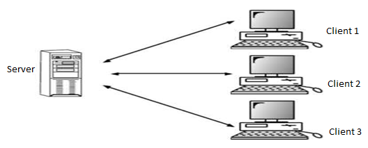
Fig: Client/server network
Q6) Explain SDN?
A6)
Software Defined Networks (SDN, also known as network virtualization) are changing what networks are, do, and how you deal with them.
SDN’s different approach, most notably centralizing many of the network control functions, deeply changes - and simplifies - how you interact with your network, particularly for network and service configuration.
The centralization of the control functions also leads to simpler, less-costly switching elements, even to the extent of offering the potential for commoditized switches.
The industry is already witnessing the rapid take-up of SDN in the data center, where the shortcomings of conventional networks are most problematic.
Drawbacks Of Existing Network
• Difficult to perform real world experiments on large scale production networks Research stagnation requires costly equipment to be procured and networks to be setup by each team for research Networks have remained the same for many years Rate of innovation in networks is slower because of lack of high-level abstraction.
• Closed Systems They are hard to collaborate meaningfully
The vendors are starting to open-up but not meaningfully.
• Network Equipment in recent decades Hardware centric Based on custom programming. Limitation in extension to network capacity
Need of faster packet switching capability Impact of these are slower Innovation and Reduced flexibility once chips are fabricated
Proprietary networking devices with proprietary software and hardware
Innovation is limited to vendor/ vendor partners huge barriers for new ideas in networking.
SDN Principles
It has Separate Control plane and Data plane entities It Execute or run Control plane software on general purpose hardware Decouple from specific networking hardware and Use commodity servers
It is having programmable data planes.
(a) Maintain, control and program data plane are isolated from a central entity
• The architecture to control is not just a networking device but an entire network.
Need for SDN
Facilitate Innovation in Network Layered architecture with Standard Open Interfaces Independent innovation at each layer Experiment and research using non-bulky, non-expensive equipment More accessibility since software can be easily developed by more vendors Speed to market no hardware fabrication cycles More flexibility with programmability Ease of customization and integration with other software Ease of network configuration applications. Fast upgrades for programming a network.
Q7) What do you mean by OSI Reference Model?
A7)
This model is based on a proposal developed by the International
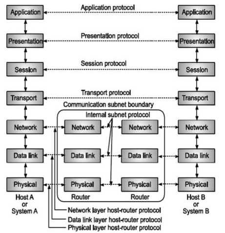
Fig – OSI Layer
Standards Organization (ISO) as a first step towards International Standardization of Protocols used in various layers. This model is called as ISO-OSI (Open Systems Interconnection) reference model because it deals with connecting open systems that is systems that are open for communication with other systems. OSI model has seven layers. The OSI model defines a layered architecture as pictured. The protocols defined in each layer are responsible for following.
Communicating with the same peer protocol layer running in the opposite computer. Providing services to the layer above it (except for the top-level application layer). Peer layer communication provides a way for each layer to exchange messages or other data.
Characteristics of the OSI Layers
The seven layers of the OSI reference model can be divided into two categories. Upper layers and lower layers. The upper layers of the OSI model deal with application issues and generally are implemented only in software. The highest layer, the application layer, is closest to the end user. Both users and application layer processes interact with software applications that contain a communication component. The term upper layer is sometimes used to refer to any layer above another layer in the OSI model. The lower layers of the OSI model handle data transport issues. The physical layer and the data link layer are implemented in hardware and software. The lowest layer, the physical layer, is closest to the physical network medium (the network cabling, for example) and is responsible for actually placing information on the medium.
Q8) Explain Functions of various Layers?
A8)
Application (Layer 7) | This layer supports application and end-user processes. Communication partners are identified, quality of service is identified, user authentication and privacy are considered, and any constraints on data syntax are identified. Everything at this layer is application-specific. This layer provides application services for file transfers, e-mail, and other network software services. |
Presentation (Layer 6) | This layer provides independence from differences in data representation (e.g., encryption) by translating from application to network format, and vice versa. The presentation layer works to transform data into the form that the application layer can accept. This layer formats and encrypts data to be sent across a network, providing freedom from compatibility problems. It is sometimes called the syntax layer. |
Session (Layer 5) | This layer establishes, manages and terminates connections between applications. The session layer sets up, co-ordinates, and terminates conversations, exchanges and dialogues between the applications at each end. It deals with session and connection co-ordination. |
Transport (Layer 4) | This layer provides transparent transfer of data between end systems, or hosts, and is responsible for end-to-end error recovery and flow control. It ensures complete data transfer. |
Network (Layer 3) | This layer provides switching and routing technologies, creating logical paths, known as virtual circuits, for transmitting data from node to node. Routing and forwarding are functions of this layer, as well as addressing, internetworking, error handling, congestion control and packet sequencing. |
Data Link (Layer 2) | At this layer, data packets are encoded and decoded into bits. It furnishes transmission protocol knowledge and management and handles errors in the physical layer, flow control and frame synchronization. The data link layer is divided into two sublayers: The Media Access Control (MAC) layer and the Logical Link Control (LLC) layer. The MAC sublayer controls how a computer on the network gains access to the data and permission to transmit it. The LLC layer controls frame synchronization, flow control and error checking. |
Physical (Layer 1) | This layer conveys the bit stream electrical impulse, light or radio signal through the network at the electrical and mechanical level. It provides the hardware means of sending and receiving data on a carrier, including defining cables, cards and physical aspects. Fast Ethernet, RS-232 and ATM are protocols with physical layer components. |
Q9) What is ring and mesh topology?
A9)
Ring Topology
In ring network, each computer is connected to the next computer, with the last one connected to first. Messages flow around the ring in one direction. Since each computer retransmits what it receives, signal loss problems are there. There is no termination because there is no end to ring.
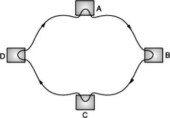
Fig. Ring topology
Advantage:
When more users are added, system slows but doesn't fail.
Disadvantages:
Failure of one computer on the ring can affect the whole network.
It is difficult to troubleshoot ring network. Adding or removing computers disturbs the entire network.
Mesh Topology
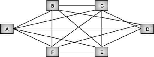
Fig. Mesh topology
Each computer is connected to other with separate cable.
Advantages
• Guaranteed communication.
• High channel capacity.
Disadvantages
Difficulty of installation and reconfiguration.
Maintenance cost.
Q10) Explain Design Issues for Layers?
A10)
The following are the design issues for the layers:
Reliability: It is a design issue of making a network that operates correctly even when it is made up of unreliable components.
Addressing: There are multiple processes running on one machine. Every layer needs a mechanism to identify senders and receivers.
Error Control: It is an important issue because physical communication circuits are not perfect. Many errors detecting and error correcting codes are available. Both sending and receiving ends must agree to use any one code.
Flow Control: If there is a fast sender at one end sending data to a slow receiver, then there must be flow control mechanism to control the loss of data by slow receivers. There are several mechanisms used for flow control such as increasing buffer size at receivers, slow down the fast sender, and so on. Some process will not be in position to accept arbitrarily long messages. This property leads to mechanisms for disassembling, transmitting and the reassembling messages.
Multiplexing and De-multiplexing: If the data has to be transmitted on transmission media separately, it is inconvenient or expensive to setup separate connection for each pair of communicating processes. So, multiplexing is needed in the physical layer at sender end and de-multiplexing is need at the receiver end.
Scalability: When network gets large, new problem arises. Thus, scalability is important so that network can continue to work well when it gets large.
Routing: When there are multiple paths between source and destination, only one route must be chosen. This decision is made on the basis of several routing algorithms, which chooses optimized route to the destination.
Q11) Explain transmission medium CAT5 and 5E?
A11)
CAT5 (also, "CAT 5" or "Category 5") is an Ethernet network cable standard defined by the Electronic Industries Association and Telecommunications Industry Association (commonly known as EIA∕TIA). CAT5 cables use the fifth generation of twisted pair Ethernet technology and, since their inception in the 1990s, became the most popular of all twisted pair cable types.
Category-5 wiring layout
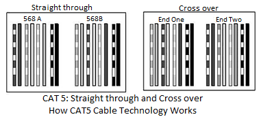
CAT5 cables contain four pairs of copper wire supporting Fast Ethernet speeds (up to 100 Mbps).
As with all other types of twisted pair EIA∕TIA cabling, CAT5 cable runs are limited to a maximum recommended run length of 100 meters (328 feet). Although CAT5 cable usually contains four pairs of copper wire, Fast Ethernet communications only utilize two pairs. The EIA∕TIA published a newer Category 5 cable specification in 2001 called CAT5e ("CAT 5e" or CAT5 enhanced) designed to better support Gigabit Ethernet speeds (up to 1000 Mbps) by utilizing all four wire pairs. CAT5e cables additionally preserve backward compatibility with Fast
Ethernet equipment. While not technically rated to support Gigabit Ethernet, CAT5 cables are capable of supporting gigabit speeds at shorter distances. The wire pairs in CAT5 cables are not twisted as tightly as those constructed to CAT5e standards and thus have a higher risk of signal interference than increases with distance.
Types of CAT5 Cables
Twisted pair cable like CAT5 comes in two main varieties, solid and stranded. Solid CAT5 cable supports longer length runs and works best in fixed wiring configurations like office buildings. Stranded CAT5 cable, on the other hand, is more pliable and better suited for shorter-distance, movable cabling such as on-the-∩y patch cables.
Although newer cable technologies like CAT6 and CAT7 have subsequently been developed, Category 5 Ethernet cable remains the popular choice for most wired local area networks (LANs), because or the combination of affordability and high performance that Ethernet gear offers.
Q12) What is Optical Fiber Cable?
A12)
Computer communication started with copper wire as the medium for carrying electrical signals encoding the data to be communicated from one computer to another. Copper as a medium of communication has a number of limitations and, in the last two decades, enormous progress has been made in using alternative media for communication.
This section reviews the main developments in the area of communication using optical signals with optical fibers as the medium of communication.
Need of Optical Network
Optical fibers are essentially very thin glass cylinders or filaments which carry signals in the form of light (optical signals). An optical network connects computers (or any other device which can generate or store data in electronic form) using optical fibers.
To facilitate data communication, an optical network also includes other optical devices to generate optical (electrical) signals from electrical (respectively optical) data, to restore optical signals after it propagates through fibers, and to route optical signals through the network.
Optical networks have found widespread use because the bandwidth of such networks using current technology is 50 tera-bits per second. In other words, it is theoretically possible to send 50 × 1012 bits per second using a single fiber.
First-generation optical networks simply replaced copper wires with optical fibers. However, there are the following important differences between copper and fiber as communication media. Optical devices are much more expensive compared to electronic devices, so it is important to optimize the use of optical network resources. A number of optical signals at different carrier wavelengths may be simultaneously carried by the same fiber. The speed at which optical signals may be communicated is far greater than the speed at which data can be processed by electronic circuits.
The Optical Transmitter
The transmitter converts an electrical analog or digital signal into a corresponding optical signal. The source of the optical signal can be either a light emitting diode, a VCSEL, or a solid-state laser diode.
The most popular wave lengths of operation for optical transmitters are 850, 1310 or 1550 nanometers. Most Fiber link and Pure Digital Fiber link transmission equipment manufactured by Communications Specialties operates at wavelengths of 850 or 1310mn.
Q13) Explain various networking devices?
A13)
Hub
A hub is basically a multiport repeater. A hub connects multiple wires coming from different branches, for example, the connector in star topology which connects different stations. Hubs cannot filter data, so data packets are sent to all connected devices. In other words, collision domain of all hosts connected through Hub remains one. Also, they do not have intelligence to find out best path for data packets which leads to inefficiencies and wastage.
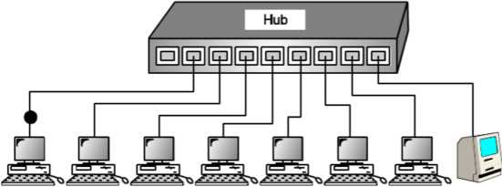
Fig: Hub
Bridge
A bridge operates at data link layer. A bridge is a repeater, with add on functionality of filtering content by reading the MAC addresses of source and destination. It is also used for interconnecting two LANs working on the same protocol. It has a single input and single output port, thus making it a 2-port device.
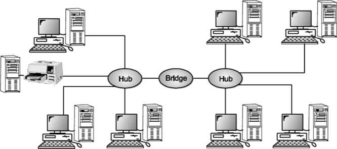
Fig: Bridge
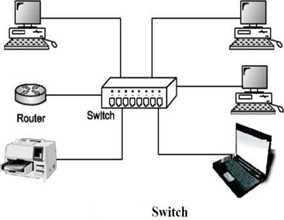
Switch
A switch is a multi port bridge with a buffer and a design that can boost its efficiency (large number of ports imply less traffic) and performance. Switch is data link layer device. Switch can perform error checking before forwarding data, that makes it very efficient as it does not forward packets that have errors and forward good packets selectively to correct port only. In other words, switch divides collision domain of hosts, but broadcast domain remains same.
Routers
A router is a device like a switch that routes data packets based on their IP addresses. Router is mainly a Network Layer device. Routers normally connect LANs and WANs together and have a dynamically updating routing table based on which they make decisions on routing the data packets. Router divide broadcast domains of hosts connected through it.
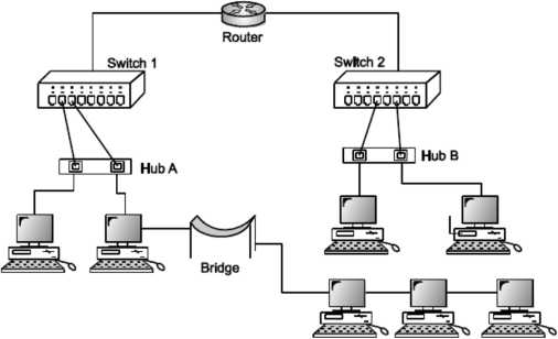
Fig: Routers
Q14) Explain FHSS in detail?
A14)
FHSS (frequency Hopping Spread Spectrum)
In FHSS ‘M’ are used for different carrier frequencies that are modulated by the input modulating signal or source information Signal.
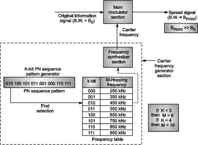
Fig: FHSS system
Here at one moment original information signal modulates one carrier frequency, generated by PN sequence, frequency table and frequency synthesizer section. At the next moment the original information signal generates another carrier frequency as shown. Modulation is done by using only one carrier frequency at a time in the FHSS system.
PN sequence generator generates k-bit pattern for every hopping period Th- For every K-bit, M-hopping frequencies are generated.
Also note that PN sequence pattern repeats after eight hoppings if K = 3 and M = 8. PN sequence pattern will repeat after sixteen hoppings if K = 4 and M = 16. Consider K = 3 and M = 8 case, the frequency table is as shown in Table below. Table showing Frequency Table.
KBit | M - Hopping Frequencies |
000 | 250 kHz |
001 | 350 kHz |
010 | 450 kHz |
Oil | 550 kHz |
100 | 650 kHz |
101 | 750 kHz |
110 | 850 kHz |
111 | 950 kHz |
Consider for cycle 1, the random PN sequence generated is 010, 100, 101, Oil, 001, 000, 110, 111.
Consider for cycle 2, the random PN sequence generated is 001, 111, 010, 110, 011, 101, 000, 100.
Thus, for cycle 1 and cycle 2, the FHSS carrier frequencies selection for different hopping periods is as shown in Fig.
Thus, if hopping period is short, then transmitter and receiver can have privacy. If an intruder or hacker tries to intercept the transmitted signal, he can only access small amount of data because of unknown PN sequence at every next hop.
Q15) Explain working of GSM?
A15)
GSM: Mobile services, System architecture, Radio interface, Protocols, Localization and calling, Handover, Security, and new data services
GSM Architecture A GSM system consists of three subsystems, the radio sub system (RSS), the network and switching subsystem (NSS), and the operation subsystem (OSS).
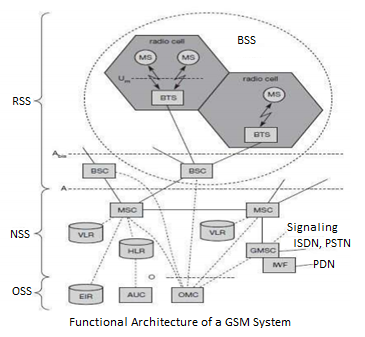
Network Switching Subsystem: The NSS is responsible for performing call processing and subscriber related functions. The switching system includes the following functional units.
Home location register (HLR): It is a database used for storage and management of subscriptions. HLR stores permanent data about subscribers, including a subscriber’s service profile, location information and activity status. When an individual buys a subscription from the PCS provider, he or she is registered in the HLR of that operator.
Visitor location register (VLR): It is a database that contains temporary information about subscribers that is needed by the MSC in order to service visiting subscribers. VLR is always integrated with the MSC. When a MS roams into a new MSC area, the VLR connected to that MSC will request data about the mobile station from the HLR. Later if the mobile station needs to make a call, VLR will be having all the information needed for call setup.
Authentication center (AUC): A unit called the AUC provides authentication and encryption parameters that verify the user’s identity and ensure the confidentiality of each call.
Equipment identity register (EIR): It is a database that contains information about the identity of mobile equipment that prevents calls from stolen, unauthorized or defective mobile stations.
Mobile switching center (MSC): The MSC performs the telephony switching functions of the system. It controls calls to and from other telephone and data systems.
Q16) Define SDN in detail?
A16)
SDN
Software Defined Networks (SDN, also known as network virtualization) are changing what networks are, do, and how you deal with them.
SDN’s different approach, most notably centralizing many of the network control functions, deeply changes - and simplifies - how you interact with your network, particularly for network and service configuration.
The centralization of the control functions also leads to simpler, less-costly switching elements, even to the extent of offering the potential for commoditized switches. The industry is already witnessing the rapid take up of SDN in the data center, where the shortcomings of conventional networks are most problematic.
Drawbacks Of Existing Network.
• Difficult to perform real world experiments on large scale production networks.
1>Research stagnation requires costly equipment to be procured and networks to be setup by each team for research
2> Networks have remained the same for many years
3> Rate of innovation in networks is slower because of lack of high-level abstraction
• Closed Systems
1>They are hard to collaborate meaningfully
2>The vendors are starting to open-up but not meaningfully
• Network Equipment in recent decades
1>Hardware centric
2>Based on custom programming
Limitation in extension to network capacity Need of faster packet switching capability Impact of these are slower Innovation and Reduced flexibility once chips are fabricated Proprietary networking devices with proprietary software and hardware
1>Innovation is limited to vendor/ vendor partners
2>Huge barriers for new ideas in networking
SDN Principles
It has Separate Control plane and Data plane entities
It Execute or run Control plane software on general purpose hardware
Decouple from specific networking hardware and Use commodity servers It is having programmable data planes
(a) Maintain, control and program data plane are isolated from a central entity
• The architecture to control is not just a networking device but an entire network.
Need for SDN
Facilitate Innovation in Network Layered architecture with Standard Open Interfaces Independent innovation at each layer Experiment and research using non-bulky, non-expensive equipment More accessibility since software can be easily developed by more vendors Speed to market no hardware fabrication cycles More flexibility with programmability Ease of customization and integration with other software Ease of network configuration applications. Fast upgrades for programming a network.
Q17) What protocol needed in computer network?
A17)
In computing, a protocol is a set of rules which is used by computers to communicate with each other across a network. A protocol is a convention or standard that controls or enables the connection, communication, and data transfer between computing endpoints. In its simplest form, a protocol can be defined as the rules governing the syntax, semantics, and synchronization of communication. Protocols may be implemented by hardware, software, or a combination of the two. At the lowest level, a protocol defines the behavior of a hardware connection.
Typical Properties
Detection of the underlying physical connection (wired or wireless), or the existence of the other endpoint or node.
Handshaking
Negotiation of various connection characteristics. How to start and end a message. Procedures on formatting a message.
What to do with corrupted or improperly formatted messages (error correction). How to detect unexpected loss of the connection, and what to do next. Termination of the session and/or connection.
Importance of Protocols
The protocols in human communication are separate rules about appearance, speaking, listening and understanding. All these rules, also called protocols of conversation, represent different layers of communication. They work together to help people successfully communicate. The need for protocols also applies to network devices. Computers have no way of learning.
Terms and Definitions
Protocol: Protocol is agreement between the communication - communicating parties on how communication is to proceed.
OR
Protocol: Protocol is strict procedure and sequence of actions to be followed in order to achieve orderly exchange of information among peer entities.
OR
Protocol: Protocol is a set of rules governing the format and meaning of the frames, packets or messages that are exchanged by the peer entities within a layer.
Protocol Stack: A list of protocols used by a certain system, one protocol per layer is called a protocol stack.
Interface: Between each pair of adjacent layers, there is an interface. The interface defines which primitive operations and services the lower layers offer to the upper one.
Network Architecture: A set of layers and protocols is called as network architecture.
Service: Services and protocols are distinct concepts although they are frequently confused. Service is a set of primitives (operations) that a layer provides to the layer above it. The service defines what operations the layer is prepared to perform on behalf of its users, but it says nothing at all about how these operations are implemented.
A service relates to an interface between two layers, with the lower layer being the service provider and the upper layer being the service user.
Q18) Explain Manchester encoding in brief?
A18)
Manchester Encoding
Manchester encoding (first published in 1949) is a synchronous clock encoding technique used by the physical layer to encode the clock and data of a synchronous bit stream. In this technique, the actual binary data to be transmitted over the cable are not sent as a sequence of logic Γs and O's (known technically as Non-Return to Zero (NRZ)). Instead, the bits are translated into a slightly different format that has a number of advantages over using straight binary encoding (i.e., NRZ).
In the Manchester encoding shown, a logic O is indicated by a O to 1 transition at the centre of the bit and a logic 1 is indicated by a 1 to O transition at the centre of the bit. Note that signal transitions do not always occur at the ‘bit boundaries’ (the division between one bit and another), but that there is always a transition at the centre of each bit. The Manchester encoding rules are summarized below:
Table
Original Data | Value Sent |
Logic 0 | 0 to 1 (upward transition at bit centre) |
Logic 1 | 1 to 0 (downward transition at bit centre) |
Note that in some cases you will see the encoding reversed, with O being represented as a O to 1 transition. The two definitions have co-existed for many years. The Ethernet Blue-Book and IEEE standards (10 Mbps) describe the method in which a Logic O is sent as O to 1 transition, and a Logic 1 as a one to zero transition (where a zero is represented by a less negative voltage on the cable).
The following diagram shows a typical Manchester encoded signal with the corresponding binary representation of the data (1,1,0,1,0,0) being sent

Note that signal transitions do not always occur at the 'bit boundaries' (the division between one bit and another), but that there is always a transition at the centre of each bit. The encoding may be alternatively viewed as a phase encoding where each bit is encoded by a positive 90-degree phase transition, or a negative 90-degree phase transition. The Manchester code is therefore sometimes known as a Biphase Code.
A Manchester encoded signal contains frequent level transitions which allow the receiver to extract the clock signal using a Digital Phase Locked Loop (DPLL) and correctly decode the value and timing of each bit. To allow reliable operation using a DPLL, the transmitted bit stream must contain a high density of bit transitions. Manchester encoding ensures this, allowing the receiving DPLL to correctly extract the clock signal. The bi-phase Manchester encoding can consume up to approximately twice the bandwidth of the original signal (20 MHz). This is the penalty for introducing frequent transitions. For a 10 Mbps LAN, the signal spectrum lies between the 5 and 20 MHz. Manchester encoding is used as the physical layer of an Ethernet LAN, where the additional bandwidth is not a significant issue for coaxial cable transmission, the limited bandwidth of CAT5e cable necessitated a more efficient encoding method for 100 Mbps transmission using a 4b∕5b MLT code. This uses three signal levels (instead of the two levels used in Manchester encoding) and therefore allows a 100 Mbps signal to occupy only 31 MHz of bandwidth. Gigabit Ethernet utilizes five levels and 8b∕10b encoding, to provide even more efficient use of the limited cable bandwidth, sending 1 Gbps within 100 MHz of bandwidth.
Example of Manchester Encoding
The pattern of bits ”01111001” encodes to “01 10 10 10 10 01 01 10”.
Another more curious example is the pattern “1 0 1 0 1 etc” which encodes to “10 01 10 01 10” which could also be viewed as “1 00 11 00 11 0 Thus for a 10 Mbps Ethernet LAN, the preamble sequence encodes to a 5 MHz square wave! (i.e., One half cycle in each 0.1 microsecond bit period.)
The Differential Manchester Coding
The Differential Manchester Code is a variation of the Manchester code. Following examples describes the differential Manchester coding.
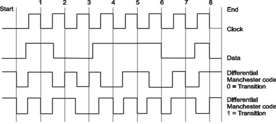
Like before, the transmission line is kept HIGH when no data is sent (before Start and after End). There are 2 encoding methods: The first is the "Transition on LOW" and the second is the "Transition on HIGH". Both methods work exactly the same. For this example, I am going to use the first method, "Transition on LOW". Here is how it goes. In the middle of each clock pulse, a transition occurs, regardless of the bit that was sent or is about to be sent. A data bit is sent during each negative clock transition. If the data bit is 0, then a polarity transition occurs (if was HIGH it goes LOW, and if it was LOW, it goes HIGH), otherwise the line remains unchanged.
In above example, the data that is transmitted is the binary '10011101' (starting from left to right). Each data bit is transmitted during negative transition of the clock. I have marked these clock transitions with red lines (except the first and last lines which indicate the start and stop of the transition). Between each bit transmission, the code line changes polarity. This is done to help the receiver recreate the clock signal and synchronize with the transmitter. As I said before, I will use the "Transition on LOW" method. This means that when a bit is transmitted, if this bit is ZERO the data line changes polarity. Otherwise, if the bit is 1 the data line polarity remains unchanged. Suppose now that we want to transmit this byte (10011101). The code line is HIGH. The transmission is initiated by pulling the code line LOW. After half a pulse, the output is pulled HIGH. This is part of the synchronization transition that occurs every middle of a bit transmission. Half a pulse next, the first bit is transmitted. The first bit is 1 (starting from left), so the code line polarity remains unchanged. After half a pulse, the code line polarity changes state and goes LOW. After one full pulse, the second bit is about to be transmitted. This bit is the 0, so the code line changes polarity and goes HIGH. The same algorithm is used to transmit all 8 bits of the data. Finally, the code line is pulled HIGH and the transmission ends.
The major difference between the Differential Manchester Code, is that the receiver does not need to know the polarity of the signal. The polarity can be figured from the line transitions. In the above example, and NOT from the code line polarity. This is something that makes this method kind a difficult to understand. It does not matter whether a logical 1 or 0 is received, but only whether the polarity is the same or is different from the previous value.
Q19) What are Uses of LAN?
A19)
Followings are the major areas where LAN is normally used
- File transfer and Access.
- Word and text processing.
- Electronic message handling.
- Remote database access.
- Personal computing.
- Digital voice transmission and storage.
- Office automation.
- Factory automation.
- Distributed Computing.
Q19) Explain PAN?
A20)
Personal Area Network (PAN)
A personal area network - PAN - is a computer network organized around an individual person. Personal area networks typically involve a mobile computer, a cell phone and/or a handheld computing device such as a PDA. You can use these networks to transfer files including email and calendar appointments, digital photos and music.
Personal area networks can be constructed with cables or be wireless.
Wireless PANs typically use Bluetooth or sometimes infrared connections. Bluetooth PANs are also sometimes called piconets.
Personal area networks generally cover a range of less than 10 meters (about 30 feet). PANs can be viewed as a special type (or subset) of local area network (LAN) that supports one person instead of a group.
A personal area network - PAN is a personal devices network equipped at a limited area. PAN ordinary has such mobile devices: cell phone, tablet, laptop. That type of network could also be wirelessly connected to Internet.
A personal area network handles the interconnection of IT devices at the surrounding of a single user. Generally, PAN contains from following such appliances: cordless mice and keyboards, cordless phone, Bluetooth.
A personal area network pros and cons.
PAN is expedient, lucrative and handy. Sometimes has a bad connection to other networks at the same radio bands. Bluetooth networks have slow data transfer speed, but comparatively safe. Bluetooth has distance limits.