Unit - 2
Data Link Layer (DLL)
Q1) Write functions of a data link layer?
A1)
Error Control: Physical layer is error prone. The errors introduced in the channel need to be corrected.
Flow Control: There might be mismatch in the transmission rate of sender and the rate at which receiver receives. This mismatch must be taken care of.
Addressing: In the network where there are multiple terminals, whom to send the data has to be specified.
Frame Synchronization: In physical layer, information is in the form of bits. These bits are grouped in blocks of frames at data link layer. In order to identify beginning and end of frames, some identification mark is put before and/or after each frame.
Link Management: In order to manage co-ordination and co-operation among terminals in the network, initiation, maintenance and termination of link is required to be done properly. These procedures are handled by data link layer. The control signals required for this purpose use the same channels on which data is exchanged. Hence, identification of control and data information is another task of data link layer.
Q2) Explain Data Link Layer Design Issues.
A2)
Physical layer provides the services to the services to the data link layer to send and receive bits over communication channels. It has a number of functions, including Dealing with transmission errors. Regulating the flow of data so that slow receivers are not swamped by fast senders. Providing a well-defined service interface to the network layer.
To complete these functions the data link layer gets the packets from network layer and it divided into the frames for transmission. Each frame has a frame header, a pay load field for holding the packet. And a frame trailer as shown in following Fig. Frame management is the main function of the data link layer. It explains what the data link layer does.
Sending machine Receiving machine

Fig. Frame Management
Q3) Write short note on framing?
A3)
Framing
When the bits of information is received from physical layer, data link layer entity identifies beginning and end of block of information i.e., frames with the help of special pattern placed by the peer entity.
The frames may be fixed length or variable length. The requirements of framing methods will vary accordingly.
In case of fixed length frames, a frame consists of a single bit followed by a particular length sequence.
Variable length frames required additional information for frame identification.
For example,
Special characters to identify beginning and end of frame.
Starting and ending flags. Character counts.
CRC Checking Methods (Checksum)
• The first framing method uses ASCII characters DLE and STX at the start of each frame and DLE and ETX at the end of the frame. Where DLE is Data Link Escape, STX is Start of Text and ETX is End of Text.
Q4) What is flow and error control?
A4)
Flow Control:
In a communication network the two communicating entities will have different speed of transmission and reception. There will be problem if sender is faster than receiver. The fast sender will swamp over the slow receiver. The “flow” of information between sender and receiver has to be “controlled”. The technique used for this is called flow control technique. Also, there will be time required to process incoming data at the receiver. This time required for processing is often more than the time for transmission. Incoming data must be checked and processed before they can be used. Hence, we require a buffer at the receiver to store the received data. This buffer is limited, therefore, before it becomes full the sender has to be informed to halt transmission temporarily. A set of procedures are required to be carried out to restrict the amount of data the sender can send before waiting for acknowledgement. This is called flow control.
Error Control:
When the data is transmitted it is going to be corrupted. We have seen how to tackle this problem by adding redundancy. Still the error is bound to occur. If such error occurs, the receiver can detect the errors and even correct them. What we can do is if error is detected by receiver, it can ask the sender to retransmit the data. This process is called Automatic Repeat Request (ARQ). Thus, error control is based on ARQ, which is retransmission of data.
Q5) Explain block coding in short?
A5)
Block Coding
A digital communication system must have higher data rate, minimum signal power, reliable transmission and minimum bandwidth requirement. The channel over which the transmission takes place is usually noisy and it will have limited bandwidth. If we have to keep the signal power minimum the signal to noise ratio will be lower. This will lead to increase in error probability (pe), as it depends on Eb/No ratio. Hence, reliability of the system suffers.
Hence, in order to improve reliability for given Eb∕N0 ratio, we can use error control coding techniques.
Error control coding techniques can correct errors, so that messages which are likely to go wrong in a noisy channel can be retrieved correctly at the receiver end.
This is also known as Forward Error Correction (FEC).
For a fixed value of error probability, it is also possible to reduce Eb/No ratio (signal power) using error control coding. Since this technique tries to overcome channel noise, it is also called channel coding.
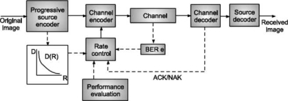
The error correcting codes are generated by adding redundancy to original message before transmitting it on a noisy channel. The channel encoder block in the transmitter does this as shown in Fig.

Fig. Channel coding in communication system
Q6) Find hamming distance C = {000, 111}?
A6)
It consists of the two codeword’s.
Weight of 000 is 0
Weight of 111 is 3.
Hamming distance between two codeword’s = 3.
Minimum hamming distance of the code = 3.
It is a linear code since addition of the two codeword’s yield one of the codeword’s 111.
Q7) Consider a code.
C = {000, 010, 001, 111}
Codeword | Weight |
000 | 0 |
010 | 1 |
001 | 1 |
111 | 3 |
A7)
Minimum hamming distance = 1
It is not a linear code as addition of OOl and 010 does not yield valid codeword i.e., 011 is not a valid codeword of this code.
Minimum Hamming Distance (dmjn): Minimum Hamming distance of a linear code is equal to minimum weight of the non-zero codeword’s in that code.
Consider a code C = {000, 010, 101, 111}
Codeword | Weight |
000 | 0 |
010 | 1 |
101 | 2 |
111 | 3 |
Since, minimum weight of non-zero code is 1.
Minimum hamming distance dmin = 1.
Q7) Write short notes on simplest protocol?
A8)
Simplest Protocol
Since the channel is noiseless, no error is introduced, hence it does not require error control. The receiver can receive all the data transmitted to by the sender at any speed. Hence, there will be no flow control.
Transmitter station A transmits a frame to receiver B whenever the network layer hands over the packet to data link layer in transmitter A.
Fig. Shows the same.
Frame

Q8) What is Stop and wait protocol?
A9)
Stop and Wait Protocol
When there is a situation in which the sender is sending data faster than the receiver can process and accept it, there will be loss of frames. We must have a feedback mechanism in this case from receiver to sender to tell the sender when to send the next frame. In case of noiseless channel, there is no error control. Hence, we have to feedback the acknowledgement whenever the frame is received as shown in Fig.

Q9) What is Go back N ARQ?
A10)
Go-Back N ARQ
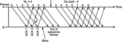
Unlike Stop and wait ARQ, in this technique transmitter continues sending frames without waiting for acknowledgement. The transmitter keeps the frames which are transmitted in a buffer called sending window till its acknowledgement is received. Let the number of frames transmitter can keep in its buffer be Ws. It is called size of sender's window. The size of window is selected on the basis of delay-bandwidth product so that channel does not remain idle and efficiency is more. The transmitter keeps on transmitting the frames in window (buffer), till acknowledgement for the first frame in the window is received. When frames O to Ws - 1 are transmitted, the transmitter waits for acknowledgement of frame O. When it is received the next frame is taken from network layer into the buffer i.e., window slides forward by one frame.
If acknowledgement for an expected frame (i.e., first frame in the window) does not reach back and time-out occurs for the frame, all the frames in the buffer are transmitted again. Since there are N = Ws frames waiting in the buffer, this technique is called Go back N ARQ.
Thus, Go back N ARQ pipelines the processing of frames to keep the channel busy.
Fig shows Go Back N ARQ.

Q10) Explain single bit error?
A11)
Single Bit Error: It means that only 1 bit of a given data unit (as a byte, character or packet) is changed from 1 to 0 or 0 to 1.
Below figure shows the effect of single bit error on a data unit. To understand the impact of change, imagine that each group of 8 bits is an ASCII character with aθ bit added to the left. In Fig. 2.7, 00000010 (ASCII/STX) was sent, meaning start of text but 00001010 (ASCII LF) was received, meaning line feed.

Sent Received
Single bit errors are the least likely type of errors in serial data transmission. To understand imagine data sent at 1 Mbps. This means that each bit lasts only 1/1,000,000s or 1 μs. For single bit error to occur, the noise must have a duration of only 1 μs, which is very rare. Noise normally lasts much longer than this.
Q11) What is burst error?
A12)
The term means that 2 or more bits in the data unit have changed from 1 to 0 or from 0 to 1.

In this case 0100010001000011 was sent, but 0101110101100011 was received. A burst error does not necessarily mean that the errors occur in consecutive bits. The length of the burst is measured from the first corrupted bit to the last corrupted bit. Some bits in between may not have been corrupted.
A burst error is more likely to occur than a single bit error. The duration of noise is normally longer than the duration of 1 bit, this means when noise affects data, it affects a set of bits. The number of bits affected depends on the data rate and duration of noise. For example, if we are sending data at 1 kbps, a noise of 1/1 OOs can affect 10 bits, if we are sending data at 1 Mbps, the same noise can affect 10,000 bits.
Redundancy
The main concept in detecting errors is redundancy. To detect errors, we need to send some extra bits with our data. These redundant bits are added by sender and removed by the receiver. Their presence allows the receiver to detect corrupted bits.
Q12) Explain HDLC?
A13)
High Level Data Link Control (HDLC)
It is the most widely used DLL protocol. It has a set of functions which provides communication service to network layer.
HDLC supports variety of applications for which it has three types of stations, two link configurations and three data transfer modes.
Types of Stations:
Primary Station: It controls operation of link. It issues commands.
Secondary Station: Primary station controls it by issuing command frames transmitted by secondary station.
Combined Station: It has features of both primary and secondary stations i.e., it issues both commands and response.
Types of Configurations:
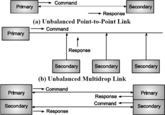
Unbalanced Configuration: It has one primary and one or more secondary stations. It supports both full duplex and half duplex configuration.
Balanced Configuration: It consists of two combined stations supporting half duplex and full duplex transmission.
These configurations are shown in Fig.

Types of Data Transfer Modes:
Normal Response Mode (NRM): Used with unbalanced configuration. Primary can initiate data transfer to a secondary. Secondary can only transfer data in response to command from primary.
Asynchronous Balanced Mode (ABM): Used with balanced configuration. Any one of the combined stations can initiate transmission without the permission of other station.
Asynchronous Response Mode (ARM): Used with unbalanced configuration secondary can initiate transmission without permission from primary. But primary has control of the link.
NRM can be used on multi drop lines and point-to-point links. ABM is most widely used. ARM is rarely used.
HDLC Frame Format
The functionality of a protocol depends on the control fields that are defined in the header and trailer.
The various data transfer modes are determined by the frame structure.

Information is attached with a header consisting of flag, address and control fields and a trailer consisting of checksum and flag.
Flag fields which are 8 bit long delimit the frame at both ends with a pattern 01111110 as discussed in before. Bit stuffing is used to achieve data transparency.
The addressing function of DLL is identifying the station that transmitted the frame and the station that will be receiving the frame. The address field specifies this. It is extendable over more than 8 bits in multiples.
Q13) Explain PPP?
A14)
Point-To-Point Protocol (PPP)
The Point-to-Point Protocol (PPP) originally emerged as an encapsulation protocol for transporting IP traffic over point-to-point links. PPP also established a standard for the assignment and management of IP addresses asynchronous (start/stop) and bit-oriented synchronous encapsulation, network protocol multiplexing, link configuration, link quality testing, error detection, and option negotiation for such capabilities as network layer address negotiation and data-compression negotiation. PPP supports these functions by providing an extensible Link Control Protocol (LCP) and a family of Network Control Protocols (NCPs) to negotiate optional configuration parameters and facilities.
PPP Components
PPP provides a method for transmitting datagrams over serial point-to-point links. PPP contains three main components: A method for encapsulating datagram over serial links. PPP uses the High-Level Data Link Control (HDLC) protocol as a basis for encapsulating datagram over point-to-point links. An extensible LCP to establish, configure, and test the data link connection.
A family of NCPs for establishing and configuring different network layer protocols. PPP is designed to allow the simultaneous use of multiple network layer protocols.
PPP Frame Format
The PPP frame format appears as shown in Fig. Below
Field length
Flag | Address | Control | Protocol | Data | FCS |
Fig. Six fields make up the PPP frame
The following descriptions summarize the PPP frame fields illustrated in Fig.
Flag: A single byte that indicates the beginning or end of a frame. The flag field consists of the binary sequence 01111110.
Address: A single byte that contains the binary sequence 11111111, the standard broadcast address. PPP does not assign individual station addresses.
Control: A single byte that contains the binary sequence 00000011, which calls for transmission of user data in an unsequenced frame. A connectionless link service similar to that of Logical Link Control (LLC) Type 1 is provided.
Protocol: Two bytes that identify the protocol encapsulated in the information field of the frame. The most up-to-date values of the protocol field are specified in the most recent Assigned Numbers Request for Comments (RFC).
Data: Zero or more bytes that contain the datagram for the protocol specified in the protocol field. The end of the information field is found by locating the closing flag sequence and allowing 2 bytes for the FCS field. The default maximum length of the information field is 1,500 bytes. By prior agreement, consenting PPP implementations can use other values for the maximum information field length.
Frame check sequence (FCS): Normally 16 bits (2 bytes). By prior agreement, consenting PPP implementations can use a 32-bit (4-byte) FCS for improved error detection.
Q14) Define ALOHA?
A15)
It is a random access scheme for transmitting information for terminals sharing the same channel. It is simple in operation. Information is transmitted over the shared channel as soon as it becomes available. If there is collision because of more stations transmitting simultaneously, they will wait for random amount of time before transmitting the information again. It is called back off.
Efficiency of ALOHA:
Let L be the length of frame (bits) (constant).
R be rate of transmission.
L
Frame time = X
Let some frame arrive at time t0 and end at to + X.
This frame will collide if there is transmission from other stations between to - X and to + X.
Vulnerable time = (to ÷ X) - (to - X)
= 2X
Let G be the total arrival rate of the system in frames/X seconds. G is also throughput of the system. Let G be total arrival rate of the system in frames/X seconds. G is also called total load of the system. With the assumption that the back-off spreads retransmissions such that new and repeated frame transmission are equally likely to occur, the number of frames transmitted in a time interval has Poisson distribution with average number of arrivals of 2G arrivals∕2X seconds. Hence, probability that k frames are generated during a given frame time are (2G)k,r
P [k transmissions in 2X seconds] = —— e 2lj
Hence, throughput S is equal to total arrival rate G times probability of successful transmission.
S = P [no collision]
= P [0 transmissions in 2X seconds]
= G≡2e-2G
= Ge-2G
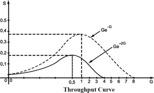
The plot of S versus G is shown in Fig.

It can be seen that the maximum value of S = at G = 0.5. That is system can achieve throughput of 18.4% only.
Q15) Explain slotted aloha?
A16)
Slotted ALOHA: Performance of ALOHA can be improved by putting a restriction on time of transmission i.e., stations will transmit only at a fixed time (Synchronize fashion). Thus, reducing the probability of collisions.
All stations keep track of transmission time slots and are allowed to initiate transmission only at beginning of slot.
Vulnerable time i.e., time of collision reduces to to - X to X i.e., X second

There are G arrivals in X seconds, (G is total arrival rate)
S = G × P [no collision]

= G × P [0 transmission in X seconds]
= Ge-G
Above equation is plotted in Fig. 3.5. Slotted ALOHA has maximum throughput of - =
36.8% at G= 1.
Q16) Explain CSMA in detail?
A17)
Carrier Sense Multiple Access Protocols
Protocols in which stations listen for carriers and take suitable action are called Carrier Sense Protocols.
Following are some carrier sense protocols:
I-Persistent CSMA:
When a station has some data to send it listens to the channel. If channel is busy, it waits until it becomes free or idle continuously sensing the channel. If channel is idle, it transmits the frame. It is called 1-persistent because whenever channel is idle the station transmits with probability 1.
Non-Persistent CSMA:
When station has some data to send, it listens to the channel and if channel is idle, it sends data. If channel is busy, it waits until it becomes free/idle. But then it does not sense the channel continuously as in 1-persistent CSMA. It waits for random period and then again senses the channel.
p-Persistent CSMA:
It applies to slotted channels. When a station is ready to transit data and channel is idle it transmits with probability p and decides not to transmit with probability q = 1 - p until next slot. If that slot is also idle it decides to transmit or defer with probability p and q. This process is repeated until either frame is transmitted or another station has started transmission. If the channel is busy, it waits until next slot and repeats above step.
Controlled Access
In controlled access, the station consults one another to find which station has the right to send. We discuss three popular methods:
Reservation
In reservation method, a station needs to make reservation before sending data. Time is divided into intervals. In each interval, a reservation frame precedes the data frames sent in that interval.
If there are N stations in the system, there are exactly N reservation mini slots in reservation frame. Each mini slot belongs to a station. When a station needs to send data frame, it makes reservation in its own mini slot. The stations that have made reservations can send their data frames after the reservation frame.
12345 12345 12345
0 | 0 | 0 | 0 | 0 | Data station 2 | 0 | 1 | 0 | 0 | 0 | Data station 3 | Data station 4 | 0 | 0 | 1 | 1 | 0 |
∣→— Reservation—>∣ frame
Reservation Access
In Fig above, it shows a situation with five stations and five mini slot reservation frames. In the first interval, only stations 1, 3 and 4 have made reservations. In the second interval, only station 1 has made a reservation.
Q17) Define IEEE 802.3?
A18)
IEEE 802.3 Standards and Frame Formats Ethernet protocols refer to the family of local-area network (LAN) covered by the IEEE 802.3. In the Ethernet standard, there are two modes of operation: half-duplex and full- duplex modes. In the half duplex mode, data are transmitted using the popular Carrier- Sense Multiple Access/Collision Detection (CSMA/CD) protocol on a shared medium. The main disadvantages of the half-duplex are the efficiency and distance limitation, in which the link distance is limited by the minimum MAC frame size. This restriction reduces the efficiency drastically for high-rate transmission. Therefore, the carrier extension technique is used to ensure the minimum frame size of 512 bytes in Gigabit Ethernet to achieve a reasonable link distance.
Four data rates are currently defined for operation over optical fiber and twisted-pair cables:
10 Mbps – IO Base-T Ethernet (IEEE 802.3)
100 Mbps - Fast Ethernet (IEEE 802.3u)
1000 Mbps - Gigabit Ethernet (IEEE 802.3z)
IO-Gigabit - 10 Gbps Ethernet (IEEE 802.3ae).
The Ethernet system consists of three basic elements:
The physical medium used to carry Ethernet signals between computers, A set of medium access control rules embedded in each Ethernet interface that allow multiple computers to fairly arbitrate access to the shared Ethernet channel, and An Ethernet frame that consists of a standardized set of bits used to carry data over the system. As with all IEEE 802 protocols, the ISO data link layer is divided into two IEEE 802 sublayers, the Media Access Control (MAC) sublayer and the MAC-client sublayer. The IEEE 802.3 physical layer corresponds to the ISO physical layer.
The MAC sub-layer has two primary responsibilities.
Data encapsulation, including frame assembly before transmission, and frame parsing/error detection during and after reception. Media access control, including initiation of frame transmission and recovery from transmission failure.