Unit - 4
Transport Layer
Q1) What are transport layer basic duties?
A1)
The basic duties of the transport layer are to accept data/message from the application (such as email application) which is running on the application layer. Transport layer then splits the received data/message into smaller units if needed. It then passes these smaller data units (TPDU) to the network layer and ensures that the pieces all arrive correctly at the other end. But before sending the data units to network layer, transport layer adds transport layer header in front of each data unit. Transport layer header prominently contains source & destination port numbers as well as sequence numbers. The transport layer is a true end-to-end layer, all the way from the source to the destination. In other words, a program on the source machine carries on a conversation with a similar program on the destination machine, using the message headers and control messages. Transport layer provides end to end flow control and error control.
Q2) Define Socket?
A2)
SOCKET
Sockets are commonly used for client/server communication. Typical system configuration places the server on one machine, with the clients on other machines. The clients connect to the server, exchange information, and then disconnect. The client and server processes only communicate with each other if and only if there is a socket at each end.
There are three types of sockets
- The stream socket
- The packet/datagram socket
- The row socket
All these sockets can be used in TCP/IP environment. These are explained below:
The Stream Socket:
Features of stream socket are as follows
- Connection-oriented
- Two-way communication
- Reliable (error free), in order delivery
- Can use the Transmission Control Protocol (TCP) e.g., telnet, ssh, http
The Datagram Socket:
Features of datagram socket are as follows
- Connectionless,
- Does not maintain an open connection,
- Each packet is independent can use the User Datagram Protocol (UDP) e.g., IP telephony
Row Socket
• Use protocols like ICMP or OSPF because these protocols do not use either stream packets or datagram packets.
Fig. shows all types of sockets.
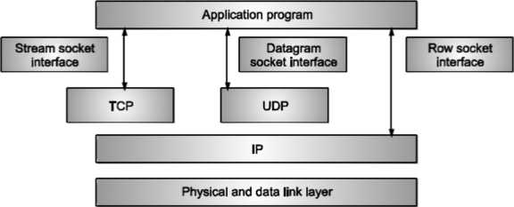
Fig: Types of sockets
Q3) Explain TCP connection establishment?
A3)
TCP Connection Establishment
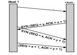
For establishing a connection, the server, passively waits for an incoming connection by executing the LISTEN and ACCEPT primitives.
The other side, say, the client, executes a CONNECT primitive, specifying the IP address and port to which it wants to connect.
The CONNECT primitive sends a TCP segment with the SYN bit 1 and ACK bit O and waits for a response. When this segment arrives at the destination, the TCP entity there checks to see if there is a process that has done a LISTEN on the port given in the Destination port field. If not, it sends a reply with the RST bit on to reject the connection. If some process is listening to the port, that process is given the incoming TCP segment. It can then either accept or reject the connection. After acceptance of the segment, an acknowledgement segment is sent back. The sequence of TCP segments sent in normal is shown in Fig. If two hosts simultaneously attempt to establish a connection between the same two sockets, the sequence of events is as illustrated in Fig.
The result of these events is that just one connection is established, not two because connections are identified by their end points.
Q4) Explain TCP connection release?
A4)
TCP Connection Release
To release a connection, either party can send a TCP segment with the FIN bit set, which means that it has no more data to transmit.
When the FIN is acknowledged, that direction is shut down for new data. Data may continue to flow indefinitely in the other direction, however.
When both directions have been shut down, the connection is released.
Four TCP segments are needed to release the connection: one FIN and one ACK for each direction.
Q5) Explain buffering?
A5)
Stream Delivery Service
TCP is stream-oriented protocol. It allows sending and receiving process to send and accept data as a stream of bytes. TCP creates an environment, in which an imaginary “tube” connects the sending and receiving process. This tube carries their data across the internet.
This imaginary environment is shown in Fig, where sender’s process writes a stream of bytes on the tube at one end and the receiver’s process reads the stream of bytes from the other end.
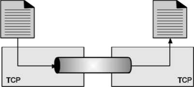
Fig. Stream delivery
Because the sending and receiving processes may not read or write the data at the same speed, TCP needs buffer storage.
Hence, TCP contains two buffers
Sending buffer and Receiving buffer Used at sender and receiver side process respectively. These buffers can be implemented by using a circular array of 1-byte locations as shown in Fig. For simplicity we have shown buffers of smaller size. Practically, the buffers are much larger than this.
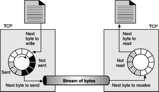
Fig. shows data movement in one direction. At the sending site, the buffer contains three types of compartments.
The white section contains empty compartments, which can be filled by the sending process. The area holds bytes that have been sent but not yet acknowledged. TCP keeps these bytes in the buffer until it receives the acknowledgement. The black area contains bytes to be sent by the sending TCP process.TCP may be able to send only part of this black section. This could be due to the slowness of the receiving process or due to the network congestion problem. When the bytes in the gray section are acknowledged, the chambers become free and get available for use to the sending process. At receiver side, the circular buffer is divided into two areas (white and gray). The white area contains empty compartments, to be filled by bytes, received from the network.
The gray area contains received bytes that can be read by the receiving process. Once the byte is read by the receiving process, the compartment is freed and added to the pool of empty compartments.
Buffering is used to handle the difference between the speed of data transmission and data reception. But only buffering is not enough, we need one more step before we can send the data. IP layer, as a service provider for TCP, needs to send data in packets, not as a stream of bytes. At transport layer, TCP groups the number of bytes together into a packet called as a segment; TCP adds a header to each segment and delivers the segment to the IP layer for transmission. The segments are encapsulated in an IP datagram and then transmitted.
Q6) What is Up-Ward Multiplexing?
A6)
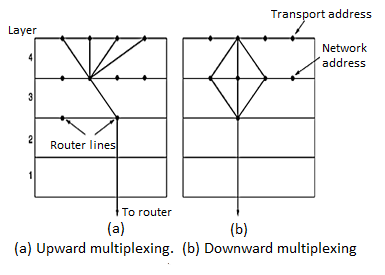
Up-Ward Multiplexing: In the figure, all the 4 distinct transport connections use the same network connection to the remote host.
When connect time forms the major component of the carrier’s bill, it is up to the transport layer to group port connections according to their destination and map each group onto the minimum number of port connections.
Q7) What is Down-Ward Multiplexing?
A7)
Down-Ward Multiplexing: If too many transport connections are mapped onto the one network connection, the performance will be poor. If too few transport connections are mapped onto one network connection, the service will be expensive. The possible solution is to have the transport layer open multiple connections and distribute the traffic among them on round-robin basis, as indicated in the below figure: With ‘k’ network connections open, the effective band width is increased by a factor of ‘k’.
Q8) Explain TCP services?
A8)
TCP Services
Stream Delivery Service TCP is stream-oriented protocol. It allows sending and receiving process to send and accept data as a stream of bytes. TCP creates an environment, in which an imaginary “tube” connects the sending and receiving process. This tube carries their data across the internet. This imaginary environment is shown in Fig. Where sender’s process writes a stream of bytes on the tube at one end and the receiver’s process reads the stream of bytes from the other end.
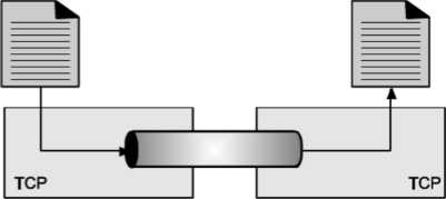
Fig. Stream delivery
Because the sending and receiving processes may not read or write the data at the same speed, TCP needs buffer storage.
Q9) Explain UDP?
A9)
User Datagram Protocol (UDP)
It is a connectionless, unreliable transport protocol. UDP provides a way for applications to send encapsulated IP datagram’s without having to establish a connection. UDP transmits segments consisting of an 8-byte header followed by the pay load. The data segment sent using the UDP protocol is called as datagram. It serves as intermediary between the application programs and network operations. It helps in process-to-process communication it uses port numbers to accomplish this task.
Another responsibility is to provide control mechanism at transport layer. It performs very limited error checking. It does not contain flow control and acknowledgement mechanism for the received packets.
It is very simple protocol with a minimum overhead. If process wants to send a small message and does not care much about the reliability, it can use UDP.
- User Datagram
UDP packets, called user datagrams, have a fixed size header of 8 bytes. Following Fig. Shows the format of a user datagram header.

Fig: User datagram header format
Q10) Draw diagram of client server network interaction?
A10)
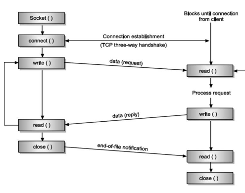
Q11) Explain TCP header?
A11)
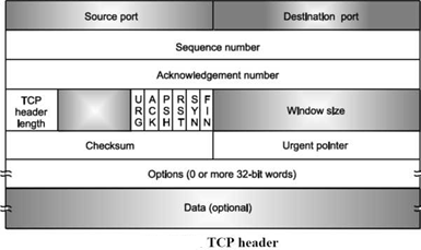

TCP protocol has fixed 20-byte header. This header is followed by
The optional field, and which is further followed by the data part.
1. Fields of TCP Header
Source Port: 16 bits.
Destination Port: 16 bits
The Source port and Destination port fields identify the local end points of the connection. The source and destination end points together identify the connection. Sequence number: 32 bits - has a dual role:
If the SYN flag is set, then this is the initial sequence number. The sequence number of the actual first data byte (and the acknowledged number in the corresponding ACK) will then be this sequence number plus 1. If the SYN flag is clear, then this is the accumulated sequence number of the first data byte of this packet for the current session.
Acknowledgement Number: It specifies the next data byte that is expected.
TCP Header length:
The TCP header length tells how many 32-bit words are contained in the TCP header. This information is needed because the Options field which is the part of TCP header is of variable length, due to that the TCP header also becomes of variable length. Next 6-bit field is unused.
Bit Flags: There are 6 one-bit flags which are given below.
URG is set to 1 if the Urgent pointer field is in use. The Urgent pointer is used to indicate a byte offset from the current sequence number at which urgent data are to be found. The ACK bit is set to 1 to indicate that the Acknowledgement number is valid. If ACK is 0, the segment does not contain an acknowledgement so the Acknowledgement number field is ignored. The PSH bit indicates Pushed data. This bit requests the receiver to deliver the data to the application upon arrival and not store the data in the buffer until a full buffer signal has been received.
The RST bit is used to reset a connection that has become confused due to a host crash or some other reason. In general, if you get a segment with the RST bit on, you have a problem in your hands.
SYN bit is used to synchronize sequence numbers. Only the first packet sent from each end should have this flag set. The FIN bit is used to release a connection. It specifies that the sender has no more data to transmit.
Window Size: The size of the window, which specifies the number of bytes that the sender/receiver is currently willing to send/receive.
Checksum: A Checksum is also provided for extra reliability. It checksums the header, the data, and the conceptual pseudo header.
Q12) Explain TCP transmission policy?
A12)
TCP Transmission Policy The following Fig. Describes the window management in TCP.
• When sender sends data, the receiver gives acknowledgement to the received data.
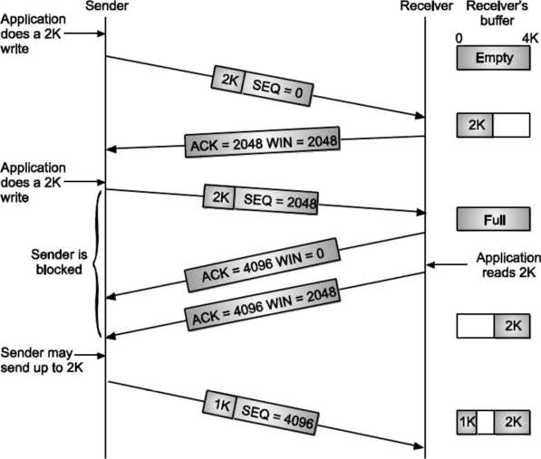
Fig: Window management in TCP
But while giving the acknowledgement, it also tells the sender about the current size of receiver window Suppose the receiver has a 4096-byte buffer, If the sender transmits a 2048-byte segment that is correctly received, the receiver will acknowledge the segment. However, since it now has only 2048 bytes of buffer space (until the application removes some data from the buffer), it will advertise a window size of 2048 for the next byte expected.
Now the sender transmits another 2048 bytes. Now consider the scenario at the receiver side buffer. Previously the buffer was having data of 2048 bytes, and now once again sender has sent the same amount of data. So, as the buffers capacity is of 4096 bytes, it gets full.
In this situation, when the receiver sends the acknowledgement back to the server, that time (as the receiver side buffer if full) it advertises its window size as 0 bytes. Now the sender must stop until the application process on the receiving host removes some data from the buffer.
When the receiver’s application reads/consumes the 2048 byte of data, it advertises the window size as 2048 bytes (which is the free space of receiver buffer). That time server gets unblocked, and it starts sending the data once again, till it gets the receiver window having non-zero-byte size. When the window is 0, the sender may not normally send segments. But sender can send the segments with two exceptions.
Urgent data may be sent, for example, to allow the user to kill the process running on the remote machine. The sender may send a 1-byte segment to make the receiver re-announce the next byte expected and window size. The TCP standard explicitly provides this option to prevent deadlock if a window announcement ever gets lost. Senders are not required to transmit data as soon as it comes from the application.
Neither are receivers required to send acknowledgements as soon as possible. For example, when the first 2 kb of data came in, sender transport entity, knowing that it had a 4 kb receiver window available, then it is completely correct to buffer the data until another 2 kb came in, so that the total size of transmitting segment will be 4 kb (as that of the size of receiving window). This freedom can be further used to improve performance.
Q13) Write short note on Nagle algorithm?
A13)
Nagle’s Algorithm
When data come into the sender one byte at a time, just send the first byte and buffer all the rest until the outstanding byte is acknowledged.
Then send all the buffered characters in one TCP segment and start buffering again until they are all acknowledged. Nagle’s algorithm is widely used by TCP implementations, but there are times when it is better to avoid it.
For example, when an X Windows application is being run over the Internet, mouse movements have to be sent to the remote computer. (The X Window system is the windowing system used on most UNIX systems.) Gathering them up to send in bursts makes the mouse cursor move inconsistently, which can irritate the users. So, it is better to send each mouse movement separately, but that degrades the TCP performance.
Q14) Explain Silly Will Syndrome?
A14)
Silly Window Syndrome
Another problem that can degrade TCP performance is the silly window syndrome. The main reason of this problem is sender sends the data in larger blocks, but the receiver side application reads the data one byte at a time.
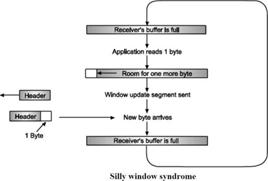
Initially, the buffer on the receiving side is full and the sender knows this as the receiver send the window of size 0 with the acknowledgement after the successful data reception. Then the receiver’s application reads one character from the buffer. Due to this receiver sends a window update to the sender saying that you can send 1 byte of data.
Then the sender sends 1 byte.
The buffer is now full, so the receiver acknowledges the 1-byte segment with advertising the window size equal to 0. This process gets repeated forever. Clark's solution is used to prevent the receiver from sending a window update for 1 byte. Instead, it is forced to wait until it has a sufficient amount of buffer space available at the receiver side.
Specifically, the receiver should not send a window update until it can handle the maximum segment size that it has advertised at the time of connection establishment or until its buffer is half empty, whichever is smaller. By not sending tiny segments, sender can also help to improve the performance. Instead, it should try to wait until it has accumulated enough space in the window to send a full segment or at least one containing half of the receiver's buffer size. Nagle's algorithm and Clark's solution to the silly window syndrome are opposite. Nagle was trying to solve the problem caused by the sending application delivering data to TCP a byte at a time. Clark was trying to solve the problem of the receiving application sucking the data up from TCP a byte at a time. Both solutions are valid and can work together. The goal is for the sender not to send small segments and the receiver not to ask for them.
Q15) Explain UDP length?
A15)
UDP Length
This is a 2-byte (16 bit) field that defines the total length of user datagram (i.e., header + data). The 16 bits can define total length of 0 to 65,535 bytes. However, the total length needs to be much less because an UDP user datagram is stored in an IP datagram with the total length of 65535 bytes. The length field in a UDP user datagram is actually not necessary. A user datagram is encapsulated in an IP datagram. There is a field in the IP datagram that defines the total length. There is another field in the IP datagram that defines the length of the header. So, after subtracting the value of second field from the first, we can find out the length of UDP datagram that is encapsulated in an IP datagram.
UDP length = IP length - IP header’s length However, the designers of the UDP protocol felt that it was more efficient for the destination UDP to calculate the length of the data from the information provided in the UDP user datagram rather than asking the IP software to supply this information. Also, we should remember that when the IP software delivers the UDP user datagram to the UDP layer, it has already dropped the IP header.
Q16) What snooping in TCP?
A16)
Snooping TCP I
Transparent extensions of TCP within the foreign agent. Snooping TCP I is about the buffering of packets sent to the mobile host Packets lost on the wireless links will be retransmitted immediately by the mobile host or foreign agent. This is called as local retransmission. The foreign agent therefore snoops the packet flow and recognizes acknowledgements in both directions. Change of TCP is only within the foreign agent. All other semantics of TCP are preserved.

End-to-end TCP connection
Fig. Snooping TCP I
Snooping TCP II
Snooping TCP II is designed to handle following two cases:
a) Data transfer to the mobile host
b) Data transfer from the mobile host
In case ‘a’, foreign agent buffers the data until it receives acknowledgement from the mobile host. Foreign agent detects packet loss via duplicated acknowledgements or time out. In case ‘b’, foreign agent detects the packet loss on the wireless link via sequence numbers and answers directly with ‘not acknowledged’ to the mobile host.
Mobile host can now retransmit data with only a very short delay.
This mechanism maintains end to end semantics Also there are no major state transfers are involved during handover. Selective retransmission with TCP acknowledgements are often cumulative. ACKNOWLEDGEMENT, acknowledges correct and in-sequence receipt of packets up to n. If simple packets are missing quite often a whole packet sequence beginning at the gap has to be retransmitted, thus wasting bandwidth. Selective retransmission is one possible over it.
RFC2018 allows for acknowledgements of single packets. This makes it possible for sender to retransmit only the missing packets. Much higher efficiency can be achieved with selective retransmission.
Q17) Write short note T-TCP?
A17)
Transaction oriented TCP (T-TCP)
T-TCP is also aimed to achieve higher efficiency.
Normally there are 3 phases in TCP: connection setup, data transmission and connection release. So, 3-way handshake needs 3 packets for setup and release respectively. Even short messages need minimum of 7 packets. RFC 1644 describes T-TCP to avoid the overhead.
With T-TCP connection setup, data transfer and connection release can be combined. Thus only 2 or 3 packets are needed.
Q18) Explain TCP timers in detail?
A18)
TCP uses multiple timers (at least conceptually) to do its work.
The most important of these is the retransmission timer.
• When a segment is sent, a retransmission timer is started.

Fig: TCP Timers
If the segment is acknowledged before the timer expires, the timer is stopped. If, on the other hand, the timer goes off before the acknowledgement comes in, the segment is retransmitted (and the timer started again). How long should the timeout interval be? This problem is much more difficult to solve in the transport layer than that of data link layer protocol. The timeout interval should be enough long such that as soon as the acknowledgement is received to the sender, the timer should be go off. Normally the acknowledgements are rarely delayed in data link layer, the absence of an acknowledgement at the expected time generally means either the frame or the acknowledgement has been lost. Lots of factors decide the performance of the network, so it is very difficult to calculate the round-trip time to the destination. If the timeout is set too short, say, Tl, unnecessary retransmissions will occur, filling the Internet with useless packets. If it is set too long, (e.g., T2), performance will suffer due to the long retransmission delay whenever a packet is lost. The best solution on this problem is to use a highly dynamic algorithm that constantly adjusts the timeout interval, based on continuous measurements of network Do not consider Round Trip Time of a retransmitted segment in the calculation of the new RTT. Do not update the value of RTT until you send a segment and receive acknowledgement without the need of retransmission
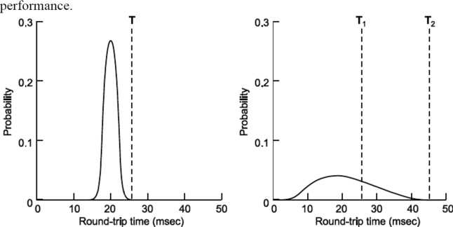
Fig: Probability density of acknowledgement arrival times in the data link layer, (b) For TCP
Q19) Write short note on Karn’s algorithm?
A19)
Karn’s Algorithm
Suppose that a segment is not acknowledged during the retransmission period and is therefore retransmitted. When the sending TCP receives an acknowledgement for this segment, it does not know if the acknowledgement is for the original segment or for the retransmitted one. The value of the new RTT is based on the departure of the segment.
However, if the original segment was lost and acknowledgement is for retransmitted one, the value of the current RTT must be calculated from the time the segment was retransmitted. This problem has been solved by Kam. Kam’s solution is very simple.
Q20) Explain QOS?
A20)
Quality Of Service (QOS)
Quality of service provided by Network layer is out of our control.
Network layer involves routers across the Internet, which we do not own (the carriers own them). If routers or the routing mechanism is faulty, it can result in introducing errors in the data and packet lost. To deal with such poor service, we can't change Network layer as we don't own those machines. Our only option is to put a further layer on top of Network layer and try to improve quality of service. Transport layer tries to provide reliable service to Application layer. Transport service can be more reliable than underlying Network service. Unreliability of Network service is hidden from higher layer. For improving quality of service, following parameters play an important role.
Connection Establishment Delay
Generally, for establishing the connection, the source does a request to the destination host; destination host gives acknowledgement to the source. If the acknowledgement is positive, the connection gets established. So, some time goes from the moment of requesting the connection till the instant at which connection is confirmed. This time difference is called as connection establishment delay. This delay should be as small as possible.
Transit Delay: This is the time difference between, the instant at which the message is sent by the transport user on the source machine and the instant when it is received by the transport user at the destination machine.
Protection: Normally, intruders monitor the network traffic. So, it is better to send the data securely. For sending the data in secure manner, some data protection mechanisms are required.
Residual Error Ratio: It is the ratio of number of lost or garbled messages to the total message sent out on the network.
Priority: Priority is associated with every network connection, which shows that some connections are more important than the other. It plays very important role in case of congestion control. During congestion, the higher priority connections get service before the lower one.
Throughput: It is nothing but number of data bytes transferred per second. Every connection has different throughput value associated with it.
Resilience: Due to some hardware/soft ware problem or due to congestion, the transport layer spontaneously terminates a connection. The resilience parameter gives the probability of such a termination.
The techniques we looked at previous sections are designed to reduce congestion and improve network performance. However, with the growth of multimedia networking, often these ad-hoc measures are not enough. Serious attempts at guaranteeing quality of service through the network and protocol design are needed. A stream of packets from a source to destination is called a flow. In connection-oriented network, all the packets belonging to a flow follow the same route; in connectionless network, they may follow different routes. The needs of each flow can be characterized by four primary parameters: reliability, delay, jitter and bandwidth. Together these parameters determine quality of service. QOS of some applications is shown in the table below.
Table
Application | Reliability | Delay | Jitter | Bandwidth |
High | Low | Low | Low | |
File Transfer | High | Low | Low | Medium |
Web access | High | Medium | Low | Medium |
Remote Login | High | Medium | Medium | Low |
Audio on Demand | Low | Low | High | Medium |
Video on Demand | Low | Low | High | High |
Telephony | Low | High | High | Low |
Video conferencing | Low | High | High | High |
Reliability:
Reliability is a characteristic that a flow needs. Lack of reliability means losing a packet or acknowledgement, which entails retransmission.
However, the sensitivity of application programs to reliability is not the same. For example, it is more important that electronic mail, file transfer, and internet access have reliable transmission than telephony or audio conferencing.
Delay:
Source to destination delay is another flow characteristic.
Again, application can tolerate delay in different degrees.
In this case, telephony, audio conferencing, video conferencing, and remote login need minimum delay, while delay in file transfer or email is less important.
Jitter:
Jitter is the variation in delay for packets belonging to the same flow.
Real time audio and video cannot tolerate high jitter, e.g., a real time video broadcast is useless if there is a 2 ms delay for the first and second packet and 16 ms delay for the third and fourth. On the other hand, it does not matter if packet carrying information in a file has different delays. The transport layer at the destination waits until all packets arrive before delivery to the application layer.
Bandwidth:
Different applications need different bandwidths. In video conferencing we need to send millions of bits per second to refresh a color screen while the total number of bits in an email may not reach even a million.